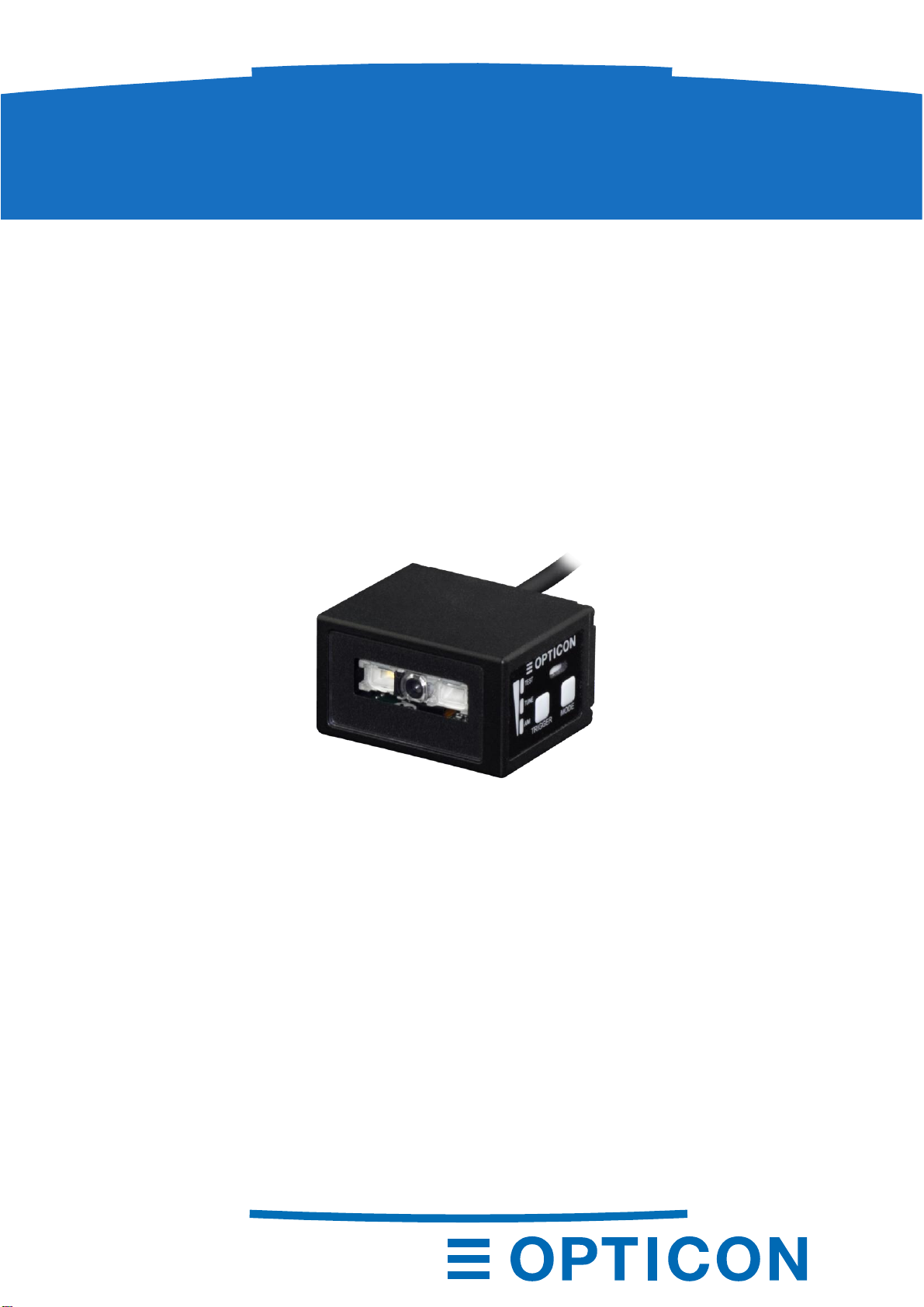
Opticon NLV-5201 User manual

SPECIFICATIONS MANUAL
NLV-5201
Fixed Position 2D Imager Scanner (Standard range model)
This manual provides specifications for
the NLV-5201 fixed position 2D scanner.
1st

NLV-5201
1st
SPECIFICATIONS MANUAL
The information in this document is subject to change without notice.
Document History
Model Number: NLV-5201 Specification Number: SS17137
Edition: 1st Original Spec Number: (SS17136)
Date: 17-July-2018
© 2018 Opticon. All rights reserved.
This manual may not, in whole or in part, be copied, photocopied, reproduced, translated or converted
to any electronic or machine readable form without prior written consent of Opticon.
Limited Warranty and Disclaimers
Please read this manual carefully before installing or using the product.
Serial Number
A serial number appears on all Opticon products. This official registration number is directly related to
the device purchased. Do not remove the serial number from your Opticon device. Removing the
serial number voids the warranty.
Warranty
Unless otherwise agreed in a written contract, all Opticon products are warranted against defects in
materials and workmanship for two years after purchase excluding batteries. Opticon will repair or, at
its option, replace products that are defective in materials or workmanship with proper use during the
warranty period. Opticon is not liable for damages caused by modifications made by a customer. In
such cases, standard repair charges will apply. If a product is returned under warranty and no defect is
found, standard repair charges will apply. Opticon assumes no liability for any direct, indirect,
consequential or incidental damages arising out of use or inability to use both the hardware and
software, even if Opticon has been informed about the possibility of such damages.
Packaging
The packing materials are recyclable. We recommend that you save all packing material to use should
you need to transport your product or send it for service. Damage caused by improper packaging
during shipment is not covered by the warranty.
Trademarks
Trademarks used are the property of their respective owners.
Opticon Inc. and Opticon Sensors Europe B.V. are wholly owned subsidiaries of
OPTOELECTRONICS Co., Ltd., 12-17, Tsukagoshi 4-chome, Warabi-shi, Saitama, Japan 335-0002.
TEL +81-(0) 48-446-1183; FAX +81-(0) 48-446-1184
Support
USA Europe
Phone: 800-636-0090 Phone: +31235692728
Web: www.opticonusa.com Web: www.opticon.com

NLV-5201
1st
SPECIFICATIONS MANUAL
Revision History
Product Name : NLV-5201
Edition
Date
Page
Section
Description of Changes
1st
2018/07/17
-
-
Initial release

NLV-5201
1st
SPECIFICATIONS MANUAL
Contents
Abstract ........................................................................................................................ 11
Overview....................................................................................................................... 12
Model details ................................................................................................................ 23
Standard...................................................................................................................................23.1
Model Description..................................................................................................................... 23.2
Basic Specifications .................................................................................................... 34
Detailed View................................................................................................................ 65
Basic Operation Mode.................................................................................................. 76
Exposure Control Method......................................................................................................... 76.1
Operation Modes and Status....................................................................................................76.2
Control Panel Operation Specifications ...................................................................................86.3
LED Indicator Specifications .................................................................................................... 96.4
Electrical Specifications ............................................................................................ 107
Electrical Characteristics........................................................................................................107.1
Optical Specifications................................................................................................ 118
Basic Optical Specifications...................................................................................................118.1
Aiming Pattern........................................................................................................................128.2
Image Range..........................................................................................................................128.3
Technical Specifications............................................................................................ 139
Barcode Test Sample.............................................................................................................149.1
Scan Area...............................................................................................................................159.2
Depth of Field.........................................................................................................................169.3
Printed Contrast Signal (PCS)................................................................................................179.4
Minimum Resolution...............................................................................................................179.5
Barcode Width........................................................................................................................179.6
Pitch, Skew and Tilt................................................................................................................189.7
Curvature................................................................................................................................189.8
Motion Tolerance....................................................................................................................199.9
Scan Speed............................................................................................................................209.10
Auto Trigger............................................................................................................................219.11
Interface Specification............................................................................................... 2210
RS-232C Interface..................................................................................................................2210.1
10.1.1 Initial Communication Settings .......................................................................................22
10.1.2 Pin Assignment...............................................................................................................22
10.1.3 Signal Level ....................................................................................................................22
10.1.4 RS-232C Interface Circuit...............................................................................................23
10.1.5 RS-232C Interface Cable................................................................................................23
USB Interface.........................................................................................................................2410.2
10.2.1 USB Interface Specifications..........................................................................................24
10.2.2 USB Connector...............................................................................................................25

NLV-5201
1st
SPECIFICATIONS MANUAL
10.2.3 USB Interface Circuit ......................................................................................................25
10.2.4 USB Interface Cable.......................................................................................................25
Environmental Specifications ................................................................................... 2611
Temperature...........................................................................................................................2611.1
Humidity..................................................................................................................................2611.2
Ambient Light Immunity..........................................................................................................2711.3
Dust and Drip Proof................................................................................................................2711.4
Key Durability .........................................................................................................................2811.5
Cable Strength .......................................................................................................................2811.6
Cable Bending Strength.........................................................................................................2811.7
Vibration Strength (without packing) ......................................................................................2911.8
Vibration Strength (in individual packing)...............................................................................2911.9
Drop Impact Strength (without packaging).........................................................................2911.10
Drop Impact Strength (in individual packaging)..................................................................2911.11
Electrical Specifications......................................................................................................2911.12
Regulatory Compliance ............................................................................................. 3012
LED Safety .............................................................................................................................3012.1
EMC........................................................................................................................................3012.2
RoHS........................................................................................................................... 3013
Reliability.................................................................................................................... 3014
Precautions................................................................................................................. 31
15
Caution and Warning..............................................................................................................3115.1
Cleaning NLV-5201................................................................................................................3215.2
Product Display.......................................................................................................... 3316
Product Label .........................................................................................................................3316.1
Address Label ........................................................................................................................3316.2
Packaging Specifications .......................................................................................... 3417
Individual Packaging Specification.........................................................................................3417.1
Collective Packaging Specification ........................................................................................3517.2
Physical Features....................................................................................................... 3618
Dimensions.............................................................................................................................36
18.1
Weight ....................................................................................................................................3618.2
Mechanical Drawing...............................................................................................................3618.3
Factory Setting........................................................................................................... 3719
Default Setting (Part 1: Readable Codes)..............................................................................3719.1
19.1.1 1D Barcodes...................................................................................................................37
19.1.2 Postal Code ....................................................................................................................37
19.1.3 GS1 DataBar, Composite Code......................................................................................38
19.1.4 Composite GS1 ..............................................................................................................38
19.1.5 2D Codes........................................................................................................................39
19.1.6 OCR font.........................................................................................................................39
Default Setting (Part 2: Read setting, trigger, buzzer) ...........................................................4019.2

NLV-5201
1st
SPECIFICATIONS MANUAL
Default Setting (Part 3: Interface communication setting)......................................................41
19.3
19.3.1 RS-232C.........................................................................................................................41
19.3.2 USB.................................................................................................................................41
Table of Figures
Figure 1: Detailed View of NLV-5201......................................................................................................6
Figure 2: Exposure Control Method ........................................................................................................7
Figure 3: Configuration Diagram ...........................................................................................................10
Figure 4: Aiming Pattern and Imaging Range.......................................................................................12
Figure 5: Reading condition...................................................................................................................13
Figure 6: Scan area and resolution .......................................................................................................15
Figure 7: Barcode width.........................................................................................................................17
Figure 8: Pitch, Skew and Tilt................................................................................................................18
Figure 9: Curvature................................................................................................................................18
Figure 10: Barcode moving vertically ....................................................................................................19
Figure 11: Scan Speed..........................................................................................................................20
Figure 12: Auto trigger...........................................................................................................................21
Figure 13: Interface Circuit (RS-232C)..................................................................................................23
Figure 14: RS-232C Loose End Interface Cable...................................................................................23
Figure 15: USB Plug (A) Pin Assignment..............................................................................................25
Figure 16: Interface Circuit (USB) .........................................................................................................25
Figure 17: USB Interface Cable ............................................................................................................25
Figure 18: Ambient Light Immunity........................................................................................................27
Figure 19: Key Durability.......................................................................................................................28
Figure 20: Cable Bending Strength.......................................................................................................28
Figure 21: Drop Impact Strength...........................................................................................................29
Figure 22: Cleaning NLV-5201..............................................................................................................32
Figure 23: Product Label.......................................................................................................................33
Figure 24: Address Label ......................................................................................................................33
Figure 25: Individual Packaging (USB) .................................................................................................34
Figure 26: Collective Packaging............................................................................................................35
Figure 27: Mechanical Drawing.............................................................................................................36

NLV-5201
1st
1
SPECIFICATIONS MANUAL
Abstract
1
This manual provides specifications for the fixed position 2D imager scanner NLV-5201 standard
barcode reading depth (SR: 113 mm).
Overview2
The NLV-5201 is a fixed position 2D imager scanner that enables high speed reading of a standard
barcode, 2D code and OCR font. Main features are as follows:
High-speed reading
The high-speed CMOS sensor (100fps) and high-speed CPU enables stress-free scanning and
fast response without being affected by movement and poor/bright lighting conditions.
Installations assist tuning function
Installed tuning function enables setting according to the target just by pressing the key. 3-colors
indicator assists installation visibly.
Motion tolerance
Capable to scan moving code with instantaneously and accurately.
3-type focus model
NLV-5201 has 3-type of focus model, other than this spec (113mm), HD: 63mm and UD: 43mm are
available. This covers reading of standard code, near distance and high resolution barcodes.
Editing function
This scanner features a unique function called “Data Editing Program” which gives a user an
almost unlimited flexibility to format the scanned data before it is sent out. Multiple 1D code, 2D
code and OCR can be (partially) combined and fixed parts can be added before it is output in one
go. It also supports GS1 application identifier and allows data edit outputting for logistics, POS,
medicines and medical instruments barcodes.
Green LED aiming and Warm-White LED Illumination
A well-defined single line of green LED light and efficient warm-white LED illumination makes it
easy to aim the scanner while providing safety and long-life.
The scanner is a RoHS directive product as declared by OPTOELECTRONICS CO.,LTD.

NLV-5201
1st
2
SPECIFICATIONS MANUAL
Model details
3
The NLV-5201 model name is constructed by a combination of following.
Model
name
Focus
Interface
Cable length
Optional
AC Adapter
NLV-5201
None
or
-HD
or
-UD
-RS232C(LE)
or
-USB
or
-USB-COM
or
-RS232C(9P)
None
None
or
-RS232C
+PS
Standard3.1
The following specs are the standard products.
Standard
Description
NLV-5201-RS232C(LE)
Standard focus, RS-232C loose end
NLV-5201-USB
Standard focus, USB-HID
Note: Other combinations only as special order, please contact sales offices for this.
Model Description3.2
Focus
Symbol
Description
None
Standard focus model (focus distance: 113mm)
-HD
High density focus model (focus distance: 63mm)
-UD
Ultra-high density focus model (focus distance: 43mm)
Interface Cable
Symbol
Description
-RS232C(LE)
RS-232C loose end cable is connected.
-USB
USB cable is connected and interface default setting is USB-HID.
-USB-COM
USB cable is connected and interface default setting is USB-COM.
-RS232C(9P)
RS-232C cable (power supply input connected to D-sub 9 pin 9) is
connected.
-RS232C
RS-232C cable (external AC adapter power supply spec) is connected.
Cable Length
Symbol
Description
None
Cable length 1.5mm
Optional AC adapter
Symbol
Description
None
AC adapter not included.
+PS
AC adapter for RS-232C external power supply is included.

NLV-5201
1st
3
SPECIFICATIONS MANUAL
Basic Specifications
4
Item
Specification
Note
Interface
RS-232C
300 to 115,200 bps
Default: 9600 bps
USB
Full Speed 12 Mbps (HID/COM)
Indicator
Status LED
Upper panel 3 colors LED
(Red, Orange, Green)
Buzzer
Loudness / tone adjustable
Optical Section
Scanning method
Monochrome CMOS area sensor
Frame rate: 100 fps
Focus distance
113 mm
Scanning light source
1 warm white LED
Aiming light source
Single line green LED
Effective pixels
0.30 million pixels (H: 640 x V: 480)
View angle
Horizontal : about 38.0°
Vertical : about 28.9°
Diagonal : about 46.4°
Supported 1D Symbologies
Symbologies
1D
UPC-A, UPC-E, UPC-A Add-on , UPC-E Add-
on, EAN-13, EAN-8, EAN-13 Add-on/EAN-8 Add-
on, JAN-13, JAN-8, Code 39, Codabar, Industrial
2 of 5, Interleaved 2 of 5, Code 93, Code 128,
GS1-128, MSI/Plessey, Code 11
Postal
Japan Postal, Intelligent Mail Barcode,
POSTNET, PLANET, Netherlands KIX Code, UK
Postal, Australian Postal, Korean Postal
Authority code
Minimum resolution (mm)
Code 39: 0.1
PCS 0.9
Curvature
Radius ≥ 20 mm (UPC12)
Wide Bar Code
Possible to read: Code 39 with 100 mm width
and resolution 0.2mm
Motion tolerance
Possible to read: UPC 0.33mm
moving at 2.54 m/s (DOF: 128 mm)
GS1/Composite
Symbologies
GS1 DataBar , GS1 DataBar Limited ,
GS1 DataBar Expanded
Composite GS1 DataBar ,
Composite GS1-128 ,
Composite EAN , Composite UPC
GS1 DataBar:
formerly called “RSS”
Minimum resolution (mm)
GS1 DataBar
Composite Code
: 0.169
: 0.169
PCS 0.9

NLV-5201
1st
4
SPECIFICATIONS MANUAL
Item
Specification
Note
Supported 2D
Symbologies
Symbologies
PDF417, MicroPDF417, Codablock F, QR Code ,
Micro QR Code, DataMatrix (ECC 200),
MaxiCode, Aztec Code, Chinese Sensible Code
Disable Code 128
when Codablock F is
enabled.
Minimum resolution (mm)
PDF417
QR Code
Data Matrix
: 0.169
: 0.169
: 0.169
PCS 0.9
Common
Scan angle
Pitch ±65°
Code 39 0.5mm
Skew ±65°
Tilt 360°
Minimum PCS
0.3 or more
UPC/EAN 0.33mm
OCR
OCR font
OCR-A
OCR-B
Imager
Image data format
Windows Bitmap, JPEG
.
Shades of gray
1024, 256, 16, 2
Range of output image
Select top/bottom (column) and left/right (row)
Resolution of output image
Full,1/2, 1/4
Interface of output image
RS-232C, USB-COM
Baud rate
USB-COM (full speed)
About 3 sec
Resolution: Full
RS-232C
(baud rate: 115.2 kbps)
About 40 sec
Power
Range of operating voltage
4.5 –5.5 V
RS-232C/USB
common
Current
consumption
Operating
Maximum
450mA
RS-232C / USB
common
Ambient temperature:
25°C
Reading
265mA (Typ.)
Auto trigger
Standby
190mA (Typ.)
Standby
40mA (Typ.)
Environmental Specifications
Temperature
Operating
0 to 50 °C
Storage
-20 to 60 °C
Humidity
Operating
20 to 85% (no condensing, no frost)
Storage
20 to 90% (no condensing, no frost)
Ambient light
immunity
Fluorescent
10,000 lx or less
UPC/EAN 0.33mm
Optical axis angle 75°
Distance 125 mm
Sunlight
100,000 lx or less
Vibration
10 Hz to 100 Hz, acceleration of 19.6 m/s2, 60
minutes per cycle, repeat once in each X, Y and
Z-direction
Drop
Drop 3 times, at each 5 faces (right, left, front,
back and top), from a height of 75 cm onto a
concrete surface.
Excluding the part
where the interface
cable is attached
Dust and drip proof
IP65 equivalent

NLV-5201
1st
5
SPECIFICATIONS MANUAL
Item
Specification
Note
Regulatory Compliance
LED safety
IEC 62471:2006 Exempt Risk Group
Warm white LED and
Green LED
EMI/RFI
VCCI クラス B / FCC Class B /
EN55032 Class B
For residential,
commercial and light-
industry
environments
European conformity
CE marking
Electromagnetic compatibility
(EMC)
EN55024 (EN61000-6-1) Class B
For residential,
commercial and light-
industry
environments
Immunity Test
ESD
immunity
No destruction
Air discharge (direct):±15 kV
Condition:
IEC61000-4-2
compliant
No malfunction
Contact discharge (direct / indirect): ±6kV
Air discharge (direct):±8 kV
Radio-
frequency
electromag
netic field.
Amplitude
modulation
Frequency
80 to 1000 MHz
Condition:
IEC61000-4-3
compliant
Level
3 V/m
AM
80% (AM)
Power
frequency
magnetic
field
Frequency
50 and 60 Hz
Condition:
IEC61000-4-8
compliant
Level
3 A/m
Physical
Features
Dimensions (mm)
Approx. 41.1 (W) ×33.0 (D) ×24.0 (H)
Except protruding
portion
Weight
Approx. 125g
Excluding the cable
Housing material
Zinc alloy diecasting

NLV-5201
1st
6
SPECIFICATIONS MANUAL
Detailed View
5
Figure 1: Detailed View of NLV-5201
No.
Name
Description
1
Scan Window
Light paths of the imager, LED illumination and aiming. Ensure that
the lens is free from dust and dirt before scanning.
2
Mounting Holes
Screw holes that can be used to mount the scanner. 2 holes on the
bottom and side. Refer to the mechanical drawing for the mounting
holes dimension.
The screw hole is M3, effective depth 3.5mm.
3
Control Panel
Control panel to execute Test mode, Tuning mode and Aiming mode.
Can also select the bank.
4
Buzzer Holes
Sound from a built-in buzzer comes out through these holes. When
they are covered, the buzzer sound will be diminished. The sound
varies depending on the settings. Buzzer sound settings are
configurable for frequency, loudness and duration.
5
Status LEDs
Indicates status by the combination of 3-color LEDs (red, orange,
green).
Refer to 6.4 LED Indicator Specifications for detail.
6
Trigger Key
Default is trigger key. When selecting mode, it operates as execution
key.
7
Mode Key
The key to select and cancel the mode. Shift to bank select mode by
long press.
X X X X X X
2. Mounting Holes
1. Scan Window
4. Buzzer Holes
7. Mode Key
6. Trigger Key
5. Status LED
3. Control Panel

NLV-5201
1st
7
SPECIFICATIONS MANUAL
Basic Operation Mode
6Exposure Control Method6.1
Exposure control has auto adjustment and tuning. Select according the usage.
Exposure Control
Auto Adjustment (default)
Tuning
Adjust exposure automatically when the reading
distance and the code to read is not fixed.
When reading distance and the code to read is
fixed, reading will stabilized by setting the
optimum exposure.
Example of use: Holing an product to read etc.
Example of use: Factory line etc.
Figure 2: Exposure Control Method
Operation Modes and Status6.2
Mode
name
Mark
Description
Normal
mode
-
Following are use as reading trigger in a readable state like operation.
・Command trigger by serial communication (USB-COM/RS-232C)
・External trigger signal (RS-232C)
・Auto trigger
・Trigger key
Test mode
TEST
Used when testing the read rate.
The read rate is displayed on the indicator LED every 10 times.
Tuning
mode
TUNE
When reading distance and the code to read is fixed, reading will stabilized by
setting the optimum exposure.
When the tuning is successes, code limited and exposures setting etc. are
registered to the current bank. Also, the reading rate is displayed on the LED
indicator.
Bank
-
Area to register the exposure etc adjusted in the tuning mode. 1 –7 can be
register to the bank, default is 1.
Aiming
mode
AIM
Aiming lights and if code can be read, displays whether the code is close to
the center coordinate of the image sensor to LED indicator.

NLV-5201
1st
8
SPECIFICATIONS MANUAL
Control Panel Operation Specifications6.3
Operation specification of the control panel allocated on the side of housing are as follows.
LED Indication
Mode Key
Trigger Key
Operation
Mode
Operation description
Trigger Key
for reading
Normal
Normal operation status.
Press once
(within 2 sec)
Mode
transition by
pressing once
Test
Used when testing the read rate.
The read rate is displayed on the indicator LED
every 10 times.
Press twice
(within 2 sec)
Mode
transition by
pressing once
Tuning
Tuning automatically perform optimum exposure
setting etc. according to the read code. When the
tuning is successes, the code is limited, and
exposures setting etc. are registered to the current
bank. Also, the reading rate when tuning is
successes is displayed on the LED indicator.
Press 3 times
(within 2 sec)
Mode
transition by
pressing once
Aiming
In the aiming mode, aiming lights and if code can
be read, displays whether the code is close to the
center coordinate of the image sensor to indicator
LED.
Press 4 times
(within 2 sec)
Press
2 seconds
or more
(Press again
to select)
Mode
transition by
pressing once
Bank
selection
By pressing the mode key for more than 2 seconds,
the bank currently used will be display on the LED.
Pressing the mode key again, bank becomes
selectable in order, and by pressing the trigger key,
the bank displayed becomes effective.
Press both key at
same time for 5 seconds,
becomes initialization
standby. And initialize by
pressing trigger key again.
Initialize
Pressing mode key and trigger key at same time for
5 seconds, it enters to the initialization standby.
Initialized by pressing trigger key with that status,
and initialization standby will be cancel by pressing
mode key.

NLV-5201
1st
9
SPECIFICATIONS MANUAL
LED Indicator Specifications6.4
The status LED’s indicate the reading result and USB communication status. In read rate mode, the
reading success rate is indicated by these three 3-color LED’s. Below is a more in-depth description
on these LED’s.
Normal mode status LED indication
Status
Reading success
Waiting for
USB communication
Communication/
Reading error
LED
indication
“Test mode”, “Tuning mode”and “Aiming mode”LED indication
Test and tuning display the reading rate for 10 times.
Reading
rate
0 - 40 %
50 - 70 %
80 - 90%
100%
Central
coordinate
Far from the center
⇒
Close to the center
LED
indication
“Bank. No.”LED indication
The LED of the bank currently used will blink by pressing the mode key for more than 2 seconds.
Bank No.
No.1
No.2
No.3
No.4
No.5
No.6
No.7
LED
indication
* Status LED legend
: OFF
: Blinking
: ON

NLV-5201
1st
10
SPECIFICATIONS MANUAL
Electrical Specifications
7
The NLV-5201 consists out of an ‘Decoder Section’for decoding 1D / 2D codes and OCR font from a
scanned image by CMOS sensor camera module, a ‘Communication Control Section’ to
communicate with a host and ‘SUB Board’ for the main power supply conversion.
The USB interface models is powered by the interface so no external power supply is needed, while
the RS-232C interface model needs an external DC 5.0V power supply.
Figure 3: Configuration Diagram
Electrical Characteristics7.1
NLV-5201 electrical characteristics are common in RS-232C and USB as follows.
Range of working voltage 5V (4.5 - 5.5V)
Current consumption
Status
Min
Typ
Max
Unit
Reading
-
265
450
mA
Auto trigger
-
190
-
mA
Standby
-
40
-
mA
* The current consumption was measured at voltage 5V and 25°C.
* Current value may very depend on the connected host type.
* USB bus-power class is USB high-power 500mA.
Camera
Section Decoder
Section SUB Board
MCU
Imaging
Lens
Illumination
Warm White
LED(1)
Power
Supply
Circuit
CPU
FROM/
LPDDR2
I/F
(RS-232C/USB)
Status LEDx3
Trigger Key
Mode Key
+5V
RS-232C
/
USB
Host
Host
Power
Supply
Circuit
3.3V←5.0V
FPC
FFC
Indicator
Control Circuit
CMOS
Image
Sensor
Illumination
Drive
Circuit
LED (1)
Power
Supply
Circuit
FPC
Buzzer
Aiming
Green LED
(1)

NLV-5201
1st
11
SPECIFICATIONS MANUAL
Optical Specifications
8Basic Optical Specifications8.1
Item
Characteristics
Scan method
CMOS area sensor (white / black)
-
Number of effective pixel
(Column) × (Row)
640 × 480 dots
Image capture speed (*1)
Frame rate
100 fps
Sensor shutter speed
Minimum shutter speed
30μs
Focal distance
Distance from the front edge of scanner
113 mm
View angle
Horizontal
Approx. 38.0°
Vertical
Approx. 28.9°
Diagonal
Approx. 46.4°
Reading light source
(LED × 1)
White LED
Warm white
Color
2600 - 3700K
Aiming light source
(LED × 1)
Green LED
Single line
Wavelength
525 nm
Scan window
Material
PMMA
*1 The fastest seed of image capture.

NLV-5201
1st
12
SPECIFICATIONS MANUAL
Aiming Pattern8.2
Aiming is used to indicate the appropriate reading distance by projecting a bar of green LED light.
The aiming specifications are as follows:
- The optical axis of the imaging field of view and the center of horizontal aiming bar coincide at a
distance of L=148±20 mm from the front edge of the scanner.
- The width of the aiming bar at a distance of L=148mm is 90%±10% of the width of the horizontal field
of view.
Figure 4: Aiming Pattern and Imaging Range
Image Range8.3
The range is ±5% from the following values.
L: Distance from the front edge of scanner
[mm]
80
100
120
140
160
180
Horizontal FOV
[mm]
57.1
70.9
98.5
98.5
112.3
126.0
Vertical FOV
[mm]
42.7
53.0
63.3
73.6
83.9
94.2
*The imaging range is not the scan area, but the imaging field of view.
Horizontal FOV
Aiming Width
Vertical FOV
Distance: L

NLV-5201
1st
13
SPECIFICATIONS MANUAL
Technical Specifications
9
The conditions for technical specifications are as follows, unless otherwise specified in each section.
Conditions
Ambient Temperature and Humidity
Room temperature, room humidity
Ambient Light
100 to 500 lux
Code Position
Near the center of the image
Angles
Pitch: α = 0°, Skew: β = 15°, Tilt: γ = 0°
Curvature
R = ∞
Power Supply Voltage
5.0 V
PCS (1D and 2D)
0.9 or higher
Scanning Test
Accept the performance with 90% or more success rate
for 10 tries of scan. One reading should be 2 seconds.
Barcode Test Sample (1D and 2D)
Specified at Section 9.1
Test chart
For 1D codes, OPTOELECTRONICS test samples
For GS1 DataBar, stacked codes and 2D codes, printed by a dedicated printer for barcode
Figure 5: Reading condition
15°
Near center of the image

NLV-5201
1st
14
SPECIFICATIONS MANUAL
Barcode Test Sample9.1
1D Barcodes
Code39
Resolution
Symbology
PCS (MRD)
Size (mm)
No. of Digits
0.10 mm
Code 39
0.9 (80)
26 × 10
16
0.127 mm
11 × 10
4
0.20 mm
100 × 10
31
0.254 mm
32.5 × 12
7
0.508 mm
36 × 25
4
Code128
Resolution
Symbology
PCS (MRD)
Size (mm)
No. of Digits
0.20 mm
Code 128
0.9 (80)
42 × 10
16
UPC/EAN
Resolution
Symbology
PCS (MRD)
Size (mm)
No. of Digits
0.33 mm
UPC/EAN
0.9/0.3
(80/23)
31.5 × 25.0
12/13
GS1 DataBar/Composite
GS1 DataBar limited
Resolution
Symbology
PCS (MRD)
Size (mm)
No. of Digits
0.169 mm
Limited
0.9 (80)
12 × 1.5
14
0.169 mm
Limited-Composite
12 × 3.0
26
2D Codes
PDF417
Resolution
Error Correction
PCS (MRD)
Size (mm)
No. of Character
0.169 mm
Level-3
0.9 (80)
23 × 10
58
0.254 mm
35 × 15
QR Code: Model-2
Resolution
Error Correction
PCS (MRD)
Size (mm)
No. of Character
0.169 mm
M
0.9 (80)
5 × 5
44
0.381 mm
11 × 11
Data Matrix
Resolution
Model
PCS (MRD)
Size (mm)
No. of Character
0.169 mm
ECC200
0.9 (80)
4 × 4
40
0.254 mm
6 × 6
* The size is outline dimensions excluding the quiet zones.
Other manuals for NLV-5201
2
Table of contents
Other Opticon Laboratory Equipment manuals