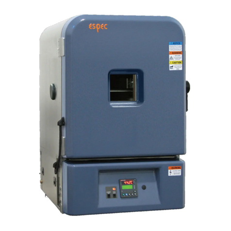
ESPEC SU Series User manual

ESPEC CORP.
Installation guide
Bench-top type
temperature (and humidity)
chamber
SH / SU
40093010010A0
May 10, 2019
This guide describes how to bring
in and install the chamber.
Before starting these works, read it
through.

Read this operation manual thoroughly before operating.
Carefully read and familiarize yourself with the "Safety precautions" section before
using this product.
Keep this operation manual handy for future reference.
Liability
ESPEC CORP. assumes NO responsibility whatsoever for accidents or equipment
trouble arising from the failure to observe handling instructions contained herein. Do not
perform any operation or handle the chamber in any way or form that is not described in
this guide or which is herein specifically prohibited. Careless usage of the sort may result
in unexpected damage to the chamber or accident.
Copyright
This guide is copyrighted by ESPEC CORP.
Copying or reproduction of this guide in whole or in part is prohibited without the written
consent of ESPEC CORP.
The contents herein are subject to change without notice.
© 2013 ESPEC CORP.

Installation guide Bench-top type temperature(humidity) chamber
ESPEC CORP. 1
Contents
1 Safety precautions ................................................................................................... 2
2 Manuals ................................................................................................................... 3
3 Installation ............................................................................................................... 4
4 How to remove moisture absorbents
(export specifications only) ...................................................................................... 9
5 Checking accessories and spare parts ................................................................. 10
6 Drainage work ....................................................................................................... 12
7 Power supply work ................................................................................................ 14
8 Power ON/OFF ...................................................................................................... 18
9 Supplying water (SH only) ..................................................................................... 19

Bench-top type temperature(humidity) chamber Installation guide
2 ESPEC CORP.
1. Safety precautions
For restricted use
The test chamber should be operated only by experienced engineers or persons who
have received training in proper usage from an experienced engineer.
Definition of an experienced engineer
A person who understands the purpose of use of the chamber, has received training
in the operation method, daily maintenance and inspections, etc., and can foresee
and prevent risks associated with common sources of hazards such as electricity, etc.
Safety indications
The following safety indications are used throughout this manual.
The following signs represent the degrees of danger to users.
DANGER
Means that extremely dangerous consequences may
arise, with the risk of death or serious injury to the user,
if the chamber is handled improperly.
WARNING
Means that dangerous consequences may arise, with the
risk of death or serious injury to the user, if the chamber
is handled improperly.
CAUTION
Means that dangerous consequences may arise, with the
risk of minor injury or light wound to the user, if the
chamber is handled improperly.
Labels that instruct the user to avoid danger.
PROHIBITED This mark means that specific actions are prohibited in
order to prevent a dangerous situation from arising.
Imperative
Action Required
This mark means that it is imperative for the user to take
specific actions (instructions) in order to prevent a
dangerous situation from arising.
Labels that indicate information on physical damage and environmental
contamination.
Notice
This mark means dangerous consequences may arise,
with the possibility of damage to equipment and
facilities, or environmental pollution, if the equipment is
handled incorrectly.
Keywords
The following keywords are used throughout this manual.
Note
Provides information necessary for gaining full
performance from the chamber or to prevent damage to
the equipment.
Procedure Explains how to operate the chamber on a step-by-step
basis.
Reference Offers additional information.

Installation guide Bench-top type temperature(humidity) chamber
ESPEC CORP. 3
ESPEC’s environmental labeling “GREEN PRODUCT Label”
ESPEC has been striving for the development of eco-friendly products by establishing
an environmentally conscious design and development guidelines for the prevention
of global warming and pollution and the promotion of resource recycling.
As part of these efforts, in April 2009, we instituted the
“GREEN PRODUCT Label” certification system for the
products intended for the Japanese market.
The “GREEN PRODUCT Label” is equivalent to the
environmental label for self-declared environmental
claims “Type II” established by the International
Organization for Standardization (ISO).
The certification criterion for green product labeling is as follows.
Products which are intended for the domestic market and satisfy the following
requirements:
Area of environmentally
conscious activity Certification criterion
Energy-saving
In comparison with the former model regarding power
consumption, more than 15% energy saving is
achieved. (When the operation pattern specified by
ESPEC is used and compared with the former model)
Energy Saving Advice: Provides tips for energy-saving operation.
2. Manuals
The manuals are organized as follows. Refer to the appropriate manual according to
the information required.
Installation guide
(booklet)
Describes how to carry in, move, and install the chamber.
Provided with the chamber. (Also provided on the CD.)
CD operation manual Explains operation, check/maintenance for the chamber.

Bench-top type temperature(humidity) chamber Installation guide
4 ESPEC CORP.
3. Installation
Installation site check
This section describes installation site and space requirements.
WARNING
Do not install the chamber outside or improper places.
It may cause fire or electrical shock.
Installation requirements
Install in an area that meets the following conditions:
On a flat, level floor strong enough to bear the weight of the chamber
Place subject to minimal mechanical vibrations
Place of minimum airborne contaminants
Place free from moisture
Place free from in flammable materials in the vicinity
Place free from combustible or corrosive gases
Place not exposed to direct sunlight but of good ventilation
Where the ambient temperature is between +5 to +35°C, humidity is max. 75%rh
range shown below (+23°C is optimum).
Place where ambient temperature does not change 5°C or more in a few
minutes.
Not directly underneath a fire alarm
Not near a heat source which generates high temperature
Close to power, water and drainage utilities
Altitude not higher than 1000m
Notice
Do not use the chamber under an ambient temperature that is out of the
specified operating range. Doing so may result in malfunction.
The operating condition is between +5C to +35C.

Installation guide Bench-top type temperature(humidity) chamber
ESPEC CORP. 5
◆ Energy Saving Advice ◆
Set the operating temperature range according
to outside conditions.
Make sure that heat exhaustion from the
chamber is not blocked off.
Temperature in the installation site
Keeping an appropriate temperature in the installation site reduces
the load on the refrigerators and heaters imposed by the ambient
temperature.
Notes for installation
List of Center of Gravity Positions
WARNING
When laying the chamber onto the floor, be careful not to catch your
fingers in the chamber, forklift or any other equipment and not to have
the chamber fall down.
When using a forklift, make sure that the front ends of the forks are not
covered by the chamber.
CHECK !
D
H
W

Bench-top type temperature(humidity) chamber Installation guide
6 ESPEC CORP.
Model
Weight
(kg) Outside dimensions (mm)
Center of gravity position (cm)
* Distance from reference
point
W H D W H D
SU
222/242 73 440 625 696
[747] 23 30 39
242-5 101 440 625 786
[834] 22 30 47
262 100 440 625 786
[834] 22 29 47
642/662 123 540 665 921
[943] 27 33 54
SH
222/242 78 440 690 696
[747] 23 34 39
242-5 106 440 690 786
[834] 22 34 47
262 105 440 690 786
[834] 22 34 46
642/662 130 540 730 921
[943] 27 37 54
* Reference point for center of gravity: Top left corner of the chamber door
* Dimensions in brackets "[ ]" include protrusions (instrumentation frame, condenser fan motor, and
cover for compressor terminals).
* Protrusions (instrumentation frame, condenser fan motor, and cover for compressor terminals) are
not taken into account in determining these center of gravity positions.
* The center of gravity position varies when options are included.
Installation condition
Install the chamber indoors in a place that satisfies the below conditions.
Flat place to withstand the weight of the chamber. (Weight of one chamber is as
follows.)
Model SH SU SH SU SH SU SH SU
222,242 222,242 262 262 642,662 642,662 242-5 242-5
100V AC 78 73
105 100 130 123 106 101
Except
100V AC 83 78
With
viewing
window
(option)
89 84 111 106 137 130 112 107
(kg)

Installation guide Bench-top type temperature(humidity) chamber
ESPEC CORP. 7
Installation space
The space shown below is necessary for taking in and taking out of the specimen,
maintenance and ventilation.
W H D D1
SH-222,242 440 690 747 440
SU-222,242 440 625 747 440
SH-262 440 690 834 440
SU-262 440 625 834 440
SH-642,662 540 730 943 540
SU-642,662 540 665 943 540
SH-242-5 440 690 834 440
SU-242-5 440 625 834 440
Including protrusions(mm)
Heat exhaust from chamber
The maximum heat load generated from the chamber is as follows.
(Ambient temperature:+23C)
SH/SU-222,242 3500
SH/SU-262 4200
SH/SU-642,662 5040
SH/SU-242-5 5700
(kJ/h)

Bench-top type temperature(humidity) chamber Installation guide
8 ESPEC CORP.
How to install
Notice
Do not move the chamber with specimens inside.
The specimens may turn over or fall off the shelves.
Install the chamber only on a flat, level floor.
An unlevel chamber can possibly cause water to backflow without smooth drainage
from the dew tray, mistakenly trigger alarms, and destabilize humidity control.
Leveling feet are found under each of the four corners of the chamber base.
< Procedure >
1) Turn the adjustable foot until at a height that the chamber sits level.
2) Place a level on the center of the test area floor, and check the level.
Levelling feet
To raise To lower

Installation guide Bench-top type temperature(humidity) chamber
ESPEC CORP. 9
4. How to remove moisture absorbents
(export specifications only)
The chamber door is fitted with a retainer before shipping from the factory, so as to
prevent the door from opening during transport. After the chamber has been installed,
detach the retainer.
< Procedure >
Peel off the moisture absorbents.
Moisture absorbents

Bench-top type temperature(humidity) chamber Installation guide
10 ESPEC CORP.
5. Checking accessories and spare parts
①Shelf ②Cable port rubber plug ③ Humidifying tray
drain hose
(SH/SU-222, 242,
262,242-5)
(SH/SU-642, 662)
④ Water tank level sensor
tank drain hose
⑤Connector ⑥Terminal plug
(For external interface)
⑦ Power plug
⑧Wet-bulb wick ⑨Cartridge fuse ⑩Class CC fuse ⑪Breaker handle
cover
⑫Stylus pen ⑬Operation manual ⑭Warranty card
No.
Accessory/Part Use Q’ty.
Check if
included
①
Shelf
Holds specimens inside the chamber.
1
②
Cable port rubber plug Use to seal the cable port. I.D. 50mm 1
③
Humidifying tray drain
hose
I.D. 8 mm hose with quick detachment plug. Use
to drain the humidifying tray and wick pan. (SH
only)
1
④
Water tank level
sensor tank drain hose
I.D. 5 mm hose with quick detachment plug. Use
to drain the water tank level sensor tank. (SH
chambers only)
1

Installation guide Bench-top type temperature(humidity) chamber
ESPEC CORP. 11
No. Accessory/Part Use Q’ty. Check if
included
⑤
Connector (For
temperature [humidity]
recorder terminal)
Use to detect dry-bulb temperature (test area) and
relative humidity. (Relative humidity detected with
SH only.)
SU 1
SH 2
⑥ Terminal plug
(For external interface)
Use to connect the chamber to the external
devices. (SH/SU-222,242, 115V AC only) 7
⑦ Power plug Use to connect socket for 20A.
(SH/SU-262,642,662,242-5,100V AC only) 1
⑧ Wet-bulb wick Box of 24 wet-bulb wicks and 1 dropper
(SH only) 1
⑨
Cartridge fuse
(Protects
instrumentation
circuits and parts.)
SH/SU-222, 242
100, 220, 230V AC B type 250V 7A
115V AC NEC spec. UL-compliant 250V
0.75A, 0.5A, 0.06A
1
1 each
SH/SU-242-5 B type 250V 7A, 6A 1 each
SH/SU-262, 642, 662
Except NEC spec. B type 250V 7A, 6A
NEC spec. 200V UL-compliant 250V 1A
0.06A
1 each
2
1
⑩
Class CC fuse
(Protects
instrumentation
circuits and parts.)
SH/SU-222, 242
115V AC NEC spec.
UL-compliant 600V 7A, 6A, 2A
1 each
SH/SU-262, 642, 662
115V AC NEC spec.
UL-compliant 600V 7A, 6A, 4A, 2A
1 each
⑪ Breaker handle cover Protects against erroneous operation. Attaches to
the breaker when the breaker is off. 1
⑫ Stylus pen Use for comfortable touchscreen operation. 1
⑬ Operation manual Provides the instructions for correct operation of
the chamber. (CD, Installation guide) 1 set
⑭ Warranty card Warranty information for the product. 1

Bench-top type temperature(humidity) chamber Installation guide
12 ESPEC CORP.
6. Drainage work
Drainage work is needed to drain water from the humidifying tray and condensation
formed in the test area out of the chamber.
Gravitational drainage is employed for the drainage system.
Keep the drain hose sloped downward to prevent the water from getting stagnant
inside and run the water into a pit.
Location of drain hose: rear underneath.
Drain tube: length about1m from the chamber, O.D. Ø18mm, I.D. Ø12mm
Notice
・
If collecting drainage in a container, regularly check water level to make sure it
does not overflow. If using the continuous water supply or additional water
tank (option), do not drain water into a container.
・
To prevent backflow into the chamber, do not share the drainage line with
other equipment. Also, leave the water tank drain hose and drain pipe ends
open to the atmosphere.
・
Raising the drain pipe about 5 cm or more off the floor or the chamber’s
supporting surface will form a pocket in the line, whereby preventing proper
drainage and possibly causing water to backflow into the dew tray or the
mechanical parts compartment. Also, if any part of the drain pipe is higher
than the drain outlet, water will not drain smoothly, possibly flooding the test
area floor.
< Procedure >
1) Connect the drain pipe from the chamber rear panel to a drainage system or run it
into container or pit. * Drain pipe ID: Ø12 mm
Whenever needed to check, maintain or run the chamber, connect the drain hose
to the nipple and drain water from the chamber. Fit the hose over the nipple and
press inward until hearing the connection catch.

Installation guide Bench-top type temperature(humidity) chamber
ESPEC CORP. 13
CAUTION
HOT WATER! Be careful of hot water drainage from the humidifying
tray shortly after operation.
Aright after the operation, it may get burned by exhaust hot water.
Water supply sensor container drain port
A socket for draining when cleaning the
water supply pump filter. (SH only)
Humidifying tray drain port
A socket for draining when performing
temperature operation or cleaning the
humidifying tray. (SH only)
Humidifying tray drain hose
I.D. 8 mm hose with plug. (SH only)
Drain pipe
Drains water accumulated in the test area or
from the dew tray.
* Equipped at the bottom of the machinery
compartment on the SU.
W
ater supply sensor container drain hose
I.D. 5 mm hose with plug. (SH only)

Bench-top type temperature(humidity) chamber Installation guide
14 ESPEC CORP.
7. Power supply work
Primary power supply requirements
Notice
・ Always take care to comply with your national regulations for power supply
installations. If a drainage pit is not located near the chamber, drain in a container.
・ External power supply cables shall be of approved type and in compliance
with IEC/EN60227 or IEC/EN60245 or any other applicable national regulation.
Prepare the power supply and power cable satisfying the following requirements.
◆ Note ◆
The following table shows the supply voltage ranges for power supply voltage fluctuation
that the chamber can operate in, but keep the range within ±5% as much as possible.
Selection
Power
supply
100V AC 1Ø
2W 50/60Hz
115V AC 1Ø
2W 60Hz
200V AC 1Ø
2W 50/60Hz
220V AC 1Ø
2W 50/60Hz
230V AC 1Ø
2W 50Hz
Power supply
voltage
fluctuation
90V to 110V 103V to 126V 190V to 220V 198V to 242V 219V to 241V
(±10%) (±10%) (-5%、+10%) (±10%) (±5%)
Maximum current per voltage specification, minimum cable diameter and fuse capacity
must be as below. Prepare a power supply that meets with chamber power supply voltage
specifications.
Power supply voltage (V AC) Max. current (A)
Min. power
cable size
(mm2)
Fuse capacity
(A)
SH-222,242
100V 50Hz/60Hz 1Ø 2W 11.3 (11.8) 2 15
115V 60Hz 1Ø 2W 12.8 (13.3) 14AWG 15
220V 50Hz/60Hz 1Ø2W 5.4 (5.7) 0.75 10
230V 50Hz 1Ø2W 5.3 (5.6) 0.75 10
SU-222,242
100V 50Hz/60Hz 1Ø 2W 9.3 (9.8) 2 15
115V 60Hz 1Ø2W 11.0 (11.5) 14AWG 15
220V 50Hz/60Hz 1Ø2W 4.5 (4.8) 0.75 10
230V 50Hz 1Ø2W 4.4 (4.7) 0.75 10
SH/SU-262
100V 50Hz/60Hz 1Ø 2W 15.0 (16.0) 2 20
200V 50Hz/60Hz 1Ø 2W 14.0 (14.5) 2 15
220V 50Hz/60Hz 1Ø 2W 13.5 (14.0) 1.5 15
230V 50Hz 1Ø 2W 13.5 (14.0) 1.5 15

Installation guide Bench-top type temperature(humidity) chamber
ESPEC CORP. 15
Power supply voltage (V AC) Max. current (A)
Min. power
cable size
(mm2)
Fuse capacity
(A)
SH/SU-
642,662
100V 50Hz/60Hz 1Ø 2W 17.5 (18.5) 2 20
200V 50Hz/60Hz 1Ø 2W 14.5 (15.0) 2 15
220V 50Hz/60Hz 1Ø 2W 14.0 (14.5) 1.5 15
230V 50Hz 1Ø 2W 14.0 (14.5) 1.5 15
SH/SU-
242-5
100V 50Hz/60Hz 1Ø 2W 16.7 (17.7) 2 20
200V 50Hz/60Hz 1Ø2W 10.6 (11.1) 2 15
220V 50Hz/60Hz 1Ø2W 9.3 (9.8) 1.5 15
230V 50Hz 1Ø2W 9.2 (9.7) 1.5 15
* Figures in parentheses are for when a viewing window is installed.
* Option:115V,200V,220V,230V AC.
WARNING
When using a leakage beaker as the primary power switch, use one that
supports high harmonics.
Malfunctions can occur with switches that do not support high-harmonics.
Primary power supply connections
The chamber is connected to the primary power supply via the power cable. It is also
grounded to prevent noise from infiltrating electronic circuits and to protect users
against electric shock which can result from leakage current.
WARNING
EXPLOSION! DO NOT ground the equipment on gas pipes.
Grounding of the sort could result in explosion.
DO NOT share ground with equipment not fitted with a leakage breaker.
The chamber's leakage breaker will not trip in the event of overcurrent,
short-circuits or surges.
DO NOT ground between equipment.
The chamber's leakage breaker will not trip in the event of overcurrent,
short-circuits or surges.
Ground the equipment WITHOUT FAIL
Unless the equipment is grounded, the leakage breaker will not trip in the event
current leaks, possibly resulting in electric shock. Furthermore, this will leave the
equipment unprotected against power supply noise. Sometimes, the temperature
(humidity) in the chamber can be destabilized.

Bench-top type temperature(humidity) chamber Installation guide
16 ESPEC CORP.
For SH/SU-222,242,262
After preparing the primary supply (see above), connect the chamber’s power
cable to the power supply.
For electrical outlet with ground
The chamber is grounded through the power cable when plugged into the
electrical outlet, so separate grounding work is not needed.
220 and 230V AC supplies have a cable with the below plug. Prepare an outlet
on the primary power system to match this plug.
For 100V AC (SH/SU-222,242 only)
For 220/230V AC (SH/SU-222,242,262 only)
For 100V AC (SH/SU-262 only)
CEE 7/7 plug
G
Grounding pole
3-pole plug with
grounding pole
W
G

Installation guide Bench-top type temperature(humidity) chamber
ESPEC CORP. 17
For SH/SU-262(200V AC),642, 662,242-5
Power cable color
Power supply
voltage L phase N phase GND
100V/200V AC Black White Green
220V/230V AC Black Black + White Green +Yellow
For SH/SU-222,242(115V AC)
Power cable color
Power supply
voltage L phase N phase GND
115V AC Black White Green +Yellow
To primary power supply
Chamber power cable
Grounding wire
Grounding
terminal
To ground
ON/OFF
switch
L N
L N
Grounding The chamber must be grounded with a max. 100 Ω
resistance against ground.

Bench-top type temperature(humidity) chamber Installation guide
18 ESPEC CORP.
8. Power ON/OFF
Power ON
< Procedure >
1) Turn the circuit breaker ON.
(On the right side of the chamber)
2) Press the instrumentation power switch.
Power OFF
< Procedure >
1) Press the instrumentation power switch.
2) Turn the circuit breaker OFF.
◆ Note ◆
Do not repeatedly turn the circuit breaker ON and immediately turn it OFF.
To protect the system, wait at least 20 seconds after you turn the circuit breaker
ON until you turn it OFF.
Instrumentation power switch
This manual suits for next models
13
Table of contents
Other ESPEC Laboratory Equipment manuals