Edelbrock Pro-Flo 3 User manual


2
GENERAL ANDROID DEVICE RECOMMENDATIONS
The Edelbrock EFI E-Tuner app is compatible with most Android based smartphones and tablets.
However, due to slight variations in device specifications and operating systems, some devices
may work better than others, and in rare cases, some devices may not function at all. If an Android
device is being supplied separately, it is highly recommended to read the following guidelines for
the best performance and user experience. Any device that is known to be “incompatible” or
“problematic” will either be specified on the Google Play Store app page or the download will fail
when attempting to download the app from the Google Play Store.
-Android Device Types:
○Smartphones (5” – 6”) or Tablets (7” – 8”)
○Screen Resolution should be at minimum 1024 x 600 pixels.
Screens sizes in the 3" - 4" or 10" - 12" range, or screens with lower resolutions are
supported but not recommended for the E-Tuner App.
-Android Operating System
○Android 4.4.
Edelbrock's E-Tuner Android app is optimized for Android 4.4.
Other android versions are supported (4.0 - 4.3, 5.0 5.1), but these devices may experience
compatibility issues.
It is NOT recommended to run or install the E-Tuner app on any device using Android 6.0
or higher at this time
-Bluetooth
○It is recommended that the Android device has at least Bluetooth 2.0 or higher.
Note: Not all devices with Bluetooth may communicate properly with the Edelbrock ECU.
-WI-FI / Data (3G/4G)
○Wi-Fi or a Data Plan will be necessary for downloading the E-Tuner app from the Google
Play store and for downloading any updates that may be released.
-To Download or Update the App
○Open the Google Play Store and search for "Edelbrock E-Tuner". This will require a
Google Account, if one is not set up, follow the on-screen tutorial to do so.
○Edelbrock will periodically push out updates to the app. It is highly recommend to
download these updates as they will include vital improvements as well as bug fixes.
○To check for updates, go to the Google Play Store or the Edelbrock website.
Starting the Edelbrock E-Tuner App:
From the Android Home Screen, find the Edelbrock E-Tuner icon and select it. The icon may
be on a different part of the home screen, or select the “All Apps” icon and find it in that
menu.

3
E-Tuner Home Menu Overview
E-Tuner Features System Info
Shortcut Buttons
All of the E-Tuner’s functions can be conveniently accessed directly from the main
menu.
1. E-Tuner Features (Sub-Menu)
a. Setup Wizard - Initiates E-Tuner's step-by-step guide to selecting & loading a proper
base map for each engine and system combination.
b. Advanced Tuning - Provided to make modifications beyond the basic settings that
were configured during the initial setup of the Pro-Flo 3.
c. Pairing Settings - Use this menu to pair an Android device with the Pro-Flo 3 ECU.
d. Gauge Displays - Displays essential parameters to monitor proper Pro-Flo 3
performance.
e. ECU Settings - Contains all the functions related to saving and restoring the ECU's
map and firmware settings.
f. Demo Mode - Use to preview the main E-Tuner app features without being connect to
an actual ECU. Press the Checkmark to enable Demo Mode.
2. System Info - This screen will display the system info when connected to an ECU (Serial #,
ECU Firmware, Map, EFI System, and App Version).
3. Main Menu Shortcut Buttons - Exit, Installation Documents, Warnings, Help, and
Connection Status.
The HELP icon provides detailed information regarding the selected menu page
currently in use.

4
Pairing Settings:
The ECU must be paired to an Android device and powered ON before attempting to connect. All
ECU connections can be managed from the E-Tuner’s Pairing Settings menu. If the Pro-Flo 3 EFI
system was purchased without an Android tablet, one must be paired to the ECU first.
Bluetooth Pairing:
When using an Android device that was not supplied with the Pro-Flo 3 EFI, follow the pairing
instructions below. E-Tuner will search for a Pro-Flo 3 ECU that is within a “discoverable” range.
This discovery range should be as close as possible, within 10-15 feet of the Bluetooth Antenna
for best results. However, this can vary between different smartphones, tablets, and vehicles. The
chances of successfully pairing will decrease if the Android device is too far away from the ECU or
if the signal is too weak.
To Pair with an ECU:
1. Turn the ignition to the ON position to power on the ECU.
2. Press ECU Search.
3. Select an ECU from the list. (A selected ECU is highlighted in RED).
4. Press “OK” to start connecting.
5. The top of the screen will flash yellow and the hourglass icon will spin while the app tries
to connect.
6. Wait 10-30 seconds until the app asks for a Pairing Code.
The pairing code can be found in several places: On the front of the ECU, on the back of the
Tablet (if purchased with the Pro-Flo 3 EFI), or on the front of the Installation Manual. This
code will be the same as the ECU Serial Number.
Example: If the ECU’s serial number is 12345, then the pairing code will be: 12345.
7. If the pairing and connection are successful, the app will show a green check mark icon.
Once connected, the Setup Wizard (see Quick Reference Guide) can be used to configure
the ECU, watch the Gauge Displays to monitor the system, or change settings in the
Advanced Tuning Section.
After pairing is complete, please follow Connecting to The ECU on the following page.

5
Connecting to the ECU, After Pairing:
It should not be necessary to repeat the paring procedure once the pairing code has been
entered and the Android device and ECU are connected. Note: If the ECU is "deleted" or un-
paired, it will be required to revisit the Pairing Procedure before any communications can be
made.
The Connection Button can be used to quickly start or stop an ECU Connection. This is shown
in the upper right-hand corner of the menu, next to the Edelbrock Logo.
Connection Button
To Start Connecting to an ECU: Press the connection button while a "Red X" icon is shown.
This icon will turn into a rotating hourglass and a yellow bar will flash at the top of the screen
until E-Tuner is connected. This icon will turn into a green check mark when E-Tuner is connected
with the ECU.
To Stop a Bluetooth Connection: Press the “Green Check Mark” icon. The icon will return to
a “Red X.”
Bluetooth connection will also be stopped each time the app is closed. If the flashing yellow bar
is active on the menu, the Connection Button can be pressed to open a popup with quick access
to the Paring Settings Menu. The E-Tuner app is programmed to try connecting to an ECU for
several minutes before stopping.
Notes on how E-Tuner connects to the ECU:
- If the ECU was connected and the E-Tuner app is closed, the app will try to reconnect the
next time the app is resumed.
- E-Tuner will try re-connecting automatically if connection is lost on any of the Gauge
Display menus.
- If the app is having a hard time connecting, the best recommendation is to turn the ignition
off then back on.
- If the ECU is power-cycled while the app is connected, E-Tuner may take a little longer to
re-synchronize and connect.
ADVANCED TUNING MENUS
Air Fuel Ratios
Specifies the AFR Setpoints at Idle, Cruise, and WOT conditions.
○Idle is applied for RPM < 1400 (Default AFR: 13.4)
○Cruise is applied for RPM > 1400 and Throttle < 50% (Default AFR: 13.9)
○WOT is applied for RPM > 1400 AND Throttle > 50% (Default AFR: 12.8)
Acceleration Fuel
Acceleration fuel adjustments provide more or less fuel during quick accelerations and throttle
openings. Values adjust the amount of fuel (%) and the duration (seconds) applied. If the engine
stumbles or hesitates on accelerations, this menu can help troubleshoot and fine-tune those
conditions. WARNING: Do not attempt to tune any acceleration fuel trims until the vehicle
has had adequate time make the necessary self-learn trim changes.

6
Fan Controls/AC Idle Kick Up
The two Fan Controls can be adjusted by setting the desired “FAN-ON” temperatures for each
fan. The ECU will switch the fans off, when Coolant Temperature drops 10° below the set "FAN-
ON" temperature. Please refer to the Pro-Flo 3 Installation Manual to properly connect the fan
controls. Fan Trigger outputs are low current, relays must be used to power fans.
Idle Tuning/Calibrate TPS
The idle control function will assist the Idle Speed Screw (on the throttle valve) maintain a
constant Idle Speed in and out of gear. Adjustments to the Idle RPM Target can only be done
once the engine is properly warmed up (170°F coolant temp).
The Idle Screw adjustment procedures are different between a Pro-Flo 4150 and Pro-Flo XT
intake manifold due to different IAC motors used for the mating throttle body. The Pro-Flo 4150
uses a PWM IAC Motor, while the Pro-Flo XT uses a Stepper IAC motor.
For Pro-Flo 4150 manifold kits, the Idle Speed screw should be adjusted with the engine idling
in Neutral until the IAC% value is between 0% and 10%. This value will vary depending on the
engine configuration, but should be less than 10% for most applications.
For Pro-Flo XT intake manifold kits, adjust the Idle Screw to a desired Idle RPM speed. Then set
the Idle Target to 50 RPM lower. Any References to IAC% should be ignored for this set up. For
example: if the Idle Screw is set to 800 RPM, the Idle Target should be set around 750 RPM.
The Calibrate TPS menu will reset the Throttle value to 10 (%) at the Idle RPM. Anytime the
throttle body idle screw is adjusted, the TPS should be calibrated so the Pro-Flo 3 system can
function properly. Pressing "Next" will continue to the Calibrate TPS Menu. This menu can be
used to reset the Throttle value to 10(%) at the Idle RPM.
Cold Start Enrichment
For cold conditions or when the engine coolant temp is below 170°F, the amount of fuel delivered
can be adjusted to help the engine start and remain running during warm up. This modifier has
no effect once the engine is warmed up. Necessary adjustments should be minimal.
On/Off
Provides control for several ECU Functions:
○Idle Control: Turning this off will pause the Idle Air Control Motor (IAC) at its current
position until enabled again.
○Self-Learning: This will control whether or not the ECU will adapt and apply changes to
the base fuel maps.
Rev-Limiter
The rev-limiter acts as a fuel-cut off limiter to protect the engine from accidental over-revs.
This limiter can be adjusted between 3000 – 8000 RPM. This value also sets the red warning
indicator on the RPM tachometer in the E-Tuner display.
Fuel Modifiers
This feature allows modifications to the base fuel map previously loaded by the Setup Wizard.

7
Modifications to the fuel modifiers should not be necessary with most applications. In some
situations, underlying differences to certain engine components may restrict the self-learning
feature from properly adjusting the base fuel calibration. In these cases, this feature allows
manual adjustments to be made by the user to reduce self-learn corrections and further assist
the self-learn process to help meet AFR Setpoints. For further information and procedure
see Adjusting Fuel Modifiers on Page #8 or contact Edelbrock Tech Line at 800-416-8628.
Crank Fuel
The Crank Fuel modifier will set the amount of extra fuel that is sprayed while the engine
is trying to start (cranking mode). This function takes affect during both warm & cold
starting conditions.
Base-Timing
This menu features a "Base Timing" function that must be performed to synchronize the ECU
and Distributor Ignition Timing. When Base Timing is active, the ECU output demands 12° BTDC
so the engine ignition timing can be manually adjusted with the distributor and timing light to
match 12° BTDC. This assures the ignition timing the ECU is commanding matches actual
engine ignition timing. Once base timing has been set, no further adjustment to the distributor
is necessary. The Spark Control menu will be used for all ignition timing modifications.
Base Timing Procedures:
1. Connect a Timing Light & slightly loosen the Distributor hold-down clamp.
2. Turn Key-On power to the ECU and verify a Bluetooth connection with the ECU.
3. Press the “Set Base Timing” icon. This will lock the Demand Ignition timing to 12° BTDC.
Once the engine is running, the ECU will hold the Demand Ignition timing at 12° BTDC.
4. Start the engine. If necessary, adjust both Throttle Body Idle Screws evenly as necessary
to keep engine running at idle.
5. Rotate the distributor to adjust engine ignition timing to 12° BTDC on engine damper
pulley with timing light..
6. Make sure the Engine Ignition Timing stays at 12° by slowly opening the throttle to raise
the RPM. Re-adjust distributor if necessary.
7. Tighten the Distributor Clamp and remove Timing Light.
8. Press Unlock Timing to restore the Ignition Control. This will also apply a standard ignition
advance curve from the ECU.
9. The distributor is now properly configured for Ignition Control.
10. To verify or make changes to the Ignition settings, go to the Spark Control menu. If no
adjustments are needed, press OK to return to the Advanced Tuning menu.
Spark Control
Enables adjustments to the ignition advance curve. Adjusting these values have the same
effect as changing the weights and springs in a traditional mechanical distributor with vacuum
advance.
○Default Timing at Idle: 15° at 1200 RPM (Typical Values 17° - 25°)
○Default Total Timing: 36° at 3000 RPM (Typical Values 34° - 38°)

8
○Default Vacuum Advance: 5° (Typical Values 4° - 10°)
NOTE: It is recommended to check with your engine builder to determine what timing values are
best for your application.
When the engine is in cranking mode, the engine ignition timing will default to 12° BTDC until the
engine RPM exceeds 300 RPM.
Idle Spark – This is the amount of advance the engine will have during idle, it will maintain this
value until engine RPM exceeds the Advance Start RPM value.
Advance Start RPM – This is the RPM value that the ignition curve will start calculating advance to
the Total Spark value at the indicated Total Spark RPM.
Total Spark – This is the maximum amount of advance the engine will have at the Total Spark
RPM value. The advance will maintain this value unless partial throttle conditions create enough
vacuum to calculate vacuum advance values.
Total Spark RPM – This is the RPM theTotal Spark value will be met.The advance curve is calculated
from the Advance Start RPM value to the Total Spark RPM value.
Vacuum Advance – This value is the maximum amount of additional advance added to the Total
Spark value under vacuum conditions.
EDELBROCK E-TUNER TUNING:
Self-Learn Idle Tuning
If idle quality is not performing as expected, some adjustment to the idle setup may help. All
adjustments should be performed at operating temperature only (170° F).
• If idle quality is excessively poor, first try resetting the self-learn from the ECU Settings page.
• Verify the idle setup procedure has been followed as outlined in the Pro-Flo 3 installation
instructions. Verify that the Idle Speed Screw has been set properly. If set correctly, the
system should be idling at the intended Idle Target value with an IAC% value.
• The self-learn may require the idle speed be increased slowly above the desired idle speed for
a few moments to adjust fuel calibration. This can be achieved by increasing the idle target in
the Advance Tuning section. Increase the idle target to 1500 RPM in slow steps, observe the
AFR Corr % allowing time for adjustment. When complete, return the setpoint to the desired
Idle Speed Target.
Adjusting Fuel Modifiers
Most applications will not require adjustments to the Fuel Modifiers. This feature has been
provided to manually adjust the base fuel map in different sections to reduce self-learn functions
when necessary.
• The vehicle should be driven for adequate time to allow for normal self-learn corrections to be
applied before making any adjustments to the Fuel Modifiers.
• The engine must be at operating temperature before any adjustments to the Fuel Modifiers.
The Fuel Modifier menu provides indicators that illuminate to indicate the different load points of
the base fuel calibration that are currently being calculated while driving.
The AFR Correction % indicates the amount of Closed Loop Correction currently applied.

9
If the vehicle is not performing well at a specific condition note the AFR Correction and light
indicating load condition: Idle, Cruise or WOT. Increase or decrease the fuel at the indicated load
point with the + or – buttons. Continue driving and allow time for corrections to be made; AFR
Correction value should decrease. Repeated adjustments may be necessary.
NOTE:
• Fuel Modifiers should only be applied if absolutely necessary.
• Many instances involving poor performance that indicate adjustment to these modifiers are
related to underlying issues related to other component failures or improper installation.
Please inspect EFI system, all related components and that Setup Wizard information related
to the installation was properly selected.
• For situations involving very poor performance Edelbrock technical assistance is advised.
• Self-Learn and Clear Self–Learn functions are provided for procedures that may be requested
when being assisted by Edelbrock technical assistance.
ECU SETTINGS MENUS
Reset Self-Learn
Clears the self-learning table. Any corrections that were previously learned will be deleted.
NOTE: Driving the vehicle through various loads, speeds, and conditions is recommended if
resetting the self-learn.
Reset Modifiers
Restores all default Advanced Tuning modifier values back to the ECU. These values should be
applicable for most engine configurations. The Idle Target and TPS must be re-calibrated after
applying. All Advanced Tuning Settings should be verified.
Save Map/Settings
Saves the current map or settings from the ECU to the Android Device. All files will be saved to
"My Maps" in Edelbrock folder on the device storage.
○Saving ECU Settings will store the current Advanced Tuning Modifiers and self-learning
progress to the Android device.
Restore Map/Settings/Firmware
Manually reload an Edelbrock File (Map, ECU Settings, Firmware) back to the ECU.
CAUTION!
- Do NOT restore/load any files while driving or while the engine is running.
- Always Power-Cycle the ECU (Key-Off 10 seconds, then Key-On) after loading a Map or
Firmware file to apply the new changes.
- When Flashing Firmware, always make sure the Bluetooth connection is stable and
consistent before attempting to load a Firmware file. It is recommended to use the
E-Tuner app while being as close as possible to the ECU or Bluetooth antenna.

10
Loading/Restoring/Flashing an ECU file:
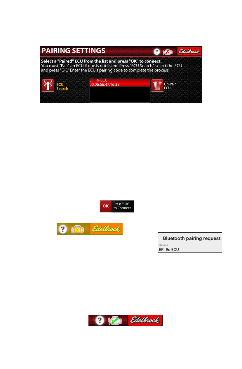
1. Turn Ignition Key-On, then connect to the ECU.
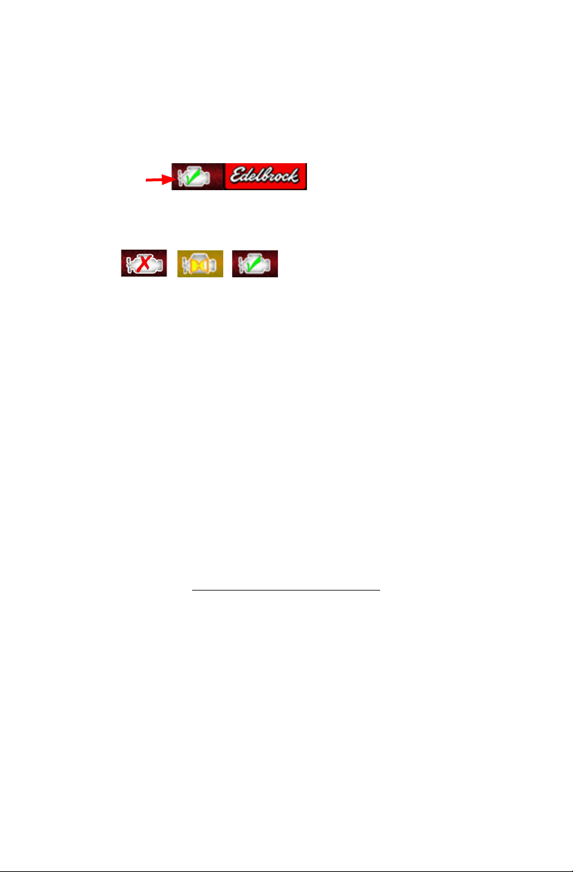
2. Verify Bluetooth Connection .
a. NOTE: For best results, try to get as close to the Bluetooth Antenna as possible while
loading a file. This is critical when loading firmware files to minimize potential ECU
corruptions.
3. Open the appropriate menu (Map*, Settings, Firmware*).
a. * Select the correct system (Pro-Flo 3).
b. The My Maps option is used to restore previous maps loaded by the Setup Wizard or
Custom Maps.
4. Select the appropriate file name.
5. Press “LOAD” once. The app may take a couple seconds to start loading.
6. It may take up to 2 minutes for a file to complete. For a map or firmware flash, Power-Cycle
the ECU (Key-Off 10 seconds, then Key-On) before pressing “FINISH”.
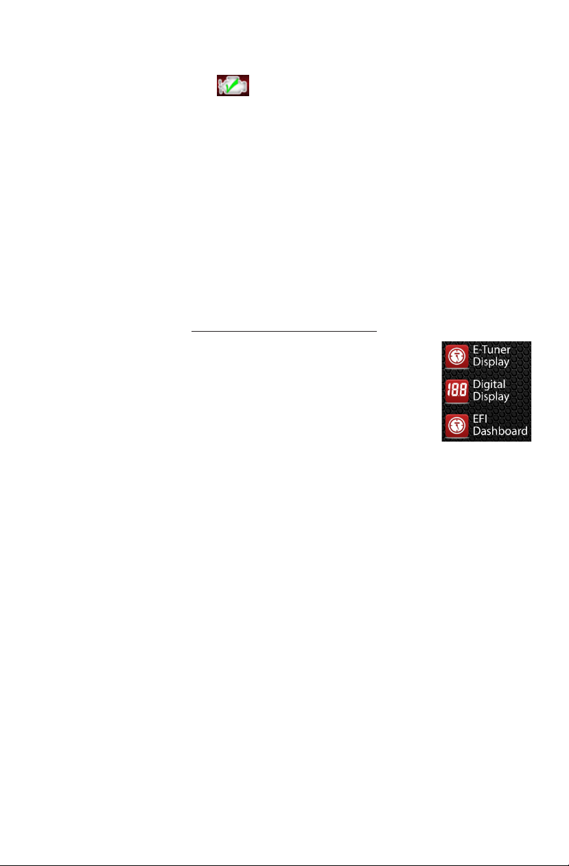
E-TUNER GAUGE DISPLAYS
The E-Tuner app features 3 different gauge displays to monitor live Engine
& ECU Sensor data. The displays vary from a more simple display (E-Tuner
Display) or more advanced displays (Digital Display and E-Tuner Dashboard).
These displays also have Status and Warning Indicators to notify when a
function is active or not within operating limits. NOTE: The Android device
must be connected to the ECU in order to use these displays.
Status Indicators - The indicator lights on each display menu notifies when a particular
function is active (on) or inactive (off). The main indicators to look at are: Closed Loop, Self-
Learning (O2 learn), and Fan1/2.
If Closed-Loop is ON, the O2 Sensor is working and the Pro-Flo 3 system is actively making
AFR Corrections. With Closed-Loop OFF, no AFR Corrections (0%) will be made. The Self-Learn
indicator informs when the Pro-Flo 3 is in Self-Learning mode and saving AFR Corrections.
The engine must be running in Closed Loop and Coolant Temperature must be above 170°F for
Self-Learning to be active. If the Self-Learning (O2 Learn) indicator is not turning ON, check to
make sure that Self-Learn has been enabled from the On/Off Menu under the Advanced Tuning
section.
The Fan indicators (Fan 1 and Fan 2) will turn ON at specified coolant Temperature. To control
the temperature when these fans turn on, go to the Fan Controls menu. The fan indicators will
turn OFF once the coolant temperature drops below the “Fan-On” temperature.
Warnings Indicators - Will appear as a RED overlay on top of the gauge if the value
exceeds its high or low limit. The red overlay will disappear once the value returns to within
normal operating range.
E-Tuner Display - Offers a simple layout, monitoring just the basic parameters. The AFR Bar
displays current air fuel ratio readings from the 02 sensor output.

11
AFR S.P. (Setpoint) displays the current AFR target value based on the Idle, Cruise and WOT AFR
targets. These targets can be adjusted from the Air Fuel Ratio menu. As the self learn adapts,
the AFR and AFR setpoint bars should become more aligned.
On the E-Tuner Display, the indicator lights to the right of the RPM gauge indicates when the
system is running in Closed Loop and Self-Learning. The indicators will switch between “GREEN”
(ON) and “RED” (OFF).
Digital Display - A numeric display for monitoring all parameters used by the Pro-Flo 3
System.
On the Digital Display, the indicators will turn “GREEN” when the function is ON, and “GRAY” when
the function is OFF.
EFI-Dashboard Display - This display offers several different layout options rather than
an all-in-one view. All information and data shown is the same as the other display pages. To
switch between different layouts, press the “channel” buttons (Ch1, Ch2, Ch3, Ch4).
The indicator icon placed in the top-right corner of the menu is a Bluetooth Connection indicator
and can be used to quickly reference if an ECU is connected. This indicator can also be used to
Start/Stop a Bluetooth connection to the ECU. This icon will turn Green when connected, Yellow
while trying to connect, and Red, when disconnected.

12
EDELBROCK E-TUNER DISPLAY DEFINITIONS:
Vacuum: When a piston moves down the cylinder bore, it creates a vacuum. The average amount
of vacuum from all cylinders is measured in the intake manifold. Using atmospheric pressure as a
zero baseline, manifold pressure is expressed as a negative value -XX Vacuum. The E-Tuner app
displays engine load in terms of inches of Mercury Vacuum. A displayed value of -10.0 means the
engine is creating 10.0 inches of vacuum. A value of 0.0 should be expected for most applications
under full throttle conditions or when sitting stationary with no RPM. Expected vacuum values for
idle can vary depending on camshaft configurations.
Race Camshaft at idle: -8.0 to -11.0
Mild Camshaft at idle: -10 to -16.0
Stock Camshaft at idle -15.0 to -20.0
RPM (Revolutions Per Minute): Refers to how “fast” an engine’s Crankshaft is rotating. The Pro-
Flo 3 EFI System calculates the RPM (Tach) Signal from the distributor sensor.
Coolant Temperature: This sensor is typically mounted in the coolant passage of the intake
manifold on the hot side of the coolant thermostat. Many functions of the ECU rely on the Coolant
Temperature as an indicator of how warm or cold the engine is. Fuel trims and Idle Control
functions rely on Coolant Temperature sensor feedback to calculate fuel trims to improve cold start
functions. Typical values should be between 170°F - 210°F.
Battery Voltage: This measures the power input being supplied to the ECU from the Battery. It is
important to make sure the vehicle’s battery is well charged and maintains a steady voltage above
12V at all times. Fluctuating battery voltage can result in poor engine performance and is usually
caused by bad grounds, bad battery or alternator. Typical values should be between 12.5 - 14.0 V.
Throttle (TPS): The Throttle indicates a percentage of how much the Throttle Blades are open
inside the Throttle Body. The TPS (Throttle Position Sensor) is what measures the actual throttle
rotation, and is reported from 0 – 100%. For all Pro-Flo 3 applications, the Throttle at Idle must
be calibrated to 10%.
Idle Air Control Percent (IAC %): The IAC% will indicate how much the Idle Air Control valve is
being used to maintain your Idle Speed. The IAC% should be used as a tool for properly adjusting
the Idle Screw to set the base Idle Speed for installations using a Pro-Flo 4150 intake manifold with
a PWM IAC motor. The Idle Screws should be adjusted so the IAC%.
Intake Air Temperature (IAT): This is the temperature of the air as it passes through the throttle
body. IAT’s can also give a good estimate of the under the hood temperature.
Fuel Pressure Sensor: Fuel Pressure is an important part of any EFI system, as any unsteadiness
or “bouncy” fuel pressures can affect performance. A drop in fuel pressure during hard acceleration
may indicate a fuel supply issue. Typical values should be between 58 - 62 psi.
ECU Temperature: This monitors the temperature of the ECU box with a sensor placed on the
ECU board. While not as critical as the other temperature readings, please be mindful of how hot
the ECU gets. The Bluetooth module may start having connectivity issues at temperatures above
130°F.
AFR (Air Fuel Ratios): AFR defines the ratio of the amount of air consumed by the engine
compared to the amount of fuel. Larger values are considered “Lean” because there is more air
than fuel in the mixture. Lower values are considered “Richer" because the mixture has more fuel
than air. Depending on the performance level of the engine Air Fuel Ratios from 12.5 to 14.5 could

13
be expected with the Direct Port EFI System. Typical AFR Setpoint Values:
Idle: 13.2 to 13.8
Cruise: 13.8 to 14.5
WOT (Wide Open Throttle): 12.4 to 12.8
AFR S.P (Air Fuel Ratios Setpoint): Air Fuel Ratio setpoint is the Air Fuel Ratio in the tailpipe
read by the O2 sensor that the EFI system is working to maintain. This value is determined by the
Vacuum, RPM, Throttle position and Air Fuel Ratio Setpoints specified in the Advance Tuning menu
/ Air Fuel Ratio section of the E-Tuner App.
AFR Corr (Air Fuel Ratio Correction): This value is the percentage of fuel correction the ECU
is applying to maintain the Air Fuel Ratio in the tailpipe at the Air Fuel Ratio Target value. As the
vehicle is driven through various load and rpm conditions, the EFI system will apply and save fuel
calibration corrections and this value will decrease.
Injection: This value is the amount of time, displayed in milliseconds, that the fuel injectors are
open to release the correct amount of fuel to maintain a proper air fuel ratio under various load
conditions.
Injection Duty: Injection Duty Cycle is the percentage of time an Injector is open during one cycle
(2 revolutions) of the engine. As engine RPM increases, available injection time decreases. A value
of 100% indicates no further injection time is available. The injector is being held wide open all
the time.
Spark Advance: This value is the final calculated Spark Advance in degrees before TDC being
commanded by the ECU. This value and curve can be adjusted in the Advanced Tuning menu/
Spark Control section of the E-Tuner App. Ignition Control components must be used for this option
to function and display values relative to actual Spark Advance.
EDELBROCK E-TUNER SETUP WIZARD DEFINITIONS:
EFI System: Edelbrock’s E-Tuner Android app can support both the Edelbrock E-Street 2 EFI
System and the Pro-Flo 3 EFI systems for V8 engines. All E-Street systems are referred to as a
Throttle Body Injection and the Pro-Flo 3 is considered Direct Port Injection.
Engine Displacement in Cubic Inches (CID): Also commonly referred to as the size of the
engine. The displacement figure represents the total air displaced by the pistons in all of an
engine’s cylinders and is expressed in cubic inches. This value in the setup wizard helps select the
proper base map for the engine configuration.
Camshaft: The setup wizard can accept 3 different camshaft profile ranges. This covers stock,
mild, and race cams. The amount of lift and duration from the camshaft will determine how much
vacuum the engine will pull under various loads, and will affect how much fuel is required to run
the engine. If the incorrect camshaft is selected in the wizard, the engine may run very poorly.
Fuel System: A 48 or 58 psi fuel system must be installed to properly run the Pro-Flo 3 EFI
System. Any return-style fuel system or an Edelbrock Fuel Sump can be used. If an adjustable fuel
pressure regulator is used, it must be set to 48 or 58 psi. On the E-Tuner Setup Wizard, return-style
and sumps at 48 or 58 psi are each considered as the same option.
Injectors: Pro-Flo 3 can support 3 Fuel Injector options: 29, 35, 60 lb/hr. The selected option must
match the injector rating included with the Pro-Flo 3 kit. The Setup Wizard will display all available
options based on the engine displacement and camshaft profile. For most applications, the 35 lb/

14
hr option will be ideal. 60 lb/hr injectors are reserved for larger engine displacements with race
camshafts, while 29 lb/hr injectors can be used for engines with less than 350 CID.
Ignition Control: All Pro-Flo 3 EFI systems are configured by default to control the engine's
Ignition Timing. Only the distributor included with the Pro-Flo 3 system can be used, and the Base
Timing setting must be configured before Ignition Timing can be controlled using E-Tuner.
Intake Manifold: Pro-Flo 3 EFI systems are compatible with 2 intake manifold options: Pro-Flo
4150 and Pro-Flo XT. The Pro-Flo 4150 accepts a 4150-Flange 4-barrel throttle body, while the
Pro-Flo XT uses a 90mm single blade throttle body. It is important to specify which manifold is
being used, since Idle Target adjustment procedures are different between these 2 options.
EFI COMMON TERM DEFINITIONS:
Direct Port Injection: Direct Port Injection offers a more "direct" way of injecting fuel into your
combustion chamber. Edelbrock's Pro-Flo 3 Direct Port System places fuel injectors in each
cylinder's intake port on the intake manifold. By delivering fuel more directly, the Pro-Flo 3 EFI
System will improve the overall performance, idle quality and throttle response over a simpler
throttle body injection (TBI) system. Installation of a Pro-Flo 3 EFI System is slightly more involved
than a TBI system as it involves replacement of the intake manifold, carburetor and distributor.
Electronic Control Unit (ECU): The ECU is an electrical module that receives inputs from sensors
and outputs signals to actuators on the Throttle Body. The ECU communicates wirelessly via
Bluetooth using the Edelbrock E-Tuner Android app to most Android devices. This allows the
adjustment of the ECU Settings and the engine’s performance in real-time.
Wide-Band Oxygen (O2) Sensor: A wideband oxygen sensor allows the air/fuel ratio to be
measured over a very broad range (10.2 up to around 21:0). The Wide Band Oxygen sensor used
for Pro-Flo 3 is a Bosch LSU 4.9. The Pro-Flo 3 EFI system has been calibrated specifically for use
with a LSU 4.9 sensor, no other oxygen sensor types may be substituted.
Base Map: The Base Fuel map is made up of coordinates of RPM (speed) and Vacuum (load) and
Injection Time. The idea of the base map is to provide the engine with a general guideline that will
let it start and run reasonably well. However, it cannot adjust for all driving conditions and slight
variations in engine configurations not covered in the wizard. This is where Closed Loop and Self-
Learning come into play to fine-tune the base map.
Closed Loop: Air Fuel Ratio feedback from the Wide Band Oxygen Sensor provides the ECU with
necessary information to calculate and adjust the Injection Time as necessary to maintain the
designated AFR Setpoint under all load conditions. The percentage of Injection Time correction the
ECU is calculating is displayed as AFR Correction (AFR Corr).
Self-Learning: This feature works side-by-side with Closed Loop control. The ECU reads the AFR
Corrections the Closed Loop is calculating and saves them to a self-learn table. The self-learn table
and Base Map values are used to calculate the final injection time necessary to maintain a proper
Air Fuel Ratio with minimal Closed Loop Corrections. As the vehicle is driven through various loads,
speeds, and conditions, the ECU continually updates and saves the self-learn table values. Initially,
higher AFR Corrections may be observed as the vehicle is driven. These corrections should be
reduced as the self-learn table is populated.
Operating Temperature: For the Pro-Flo 3 EFI system, operating temperature is a coolant
temperature of 170°F. It is very important that the correct temperature thermostat (180°F),

15
as specified in the instructions manual is installed to ensure the engine meets this operating
temperature. An improper thermostat will prolong warm up times and cause poor performance
and fuel mileage.
Recommended Self-Learning Drive Cycles:
The following is a guideline to driving procedures that helps assist the self-learning function of the
Pro-Flo 3 EFI system. Please note that there is never really a time when the self-learn function
is actually complete. The system is always adjusting for various weather, road load and engine
functions that may affect engine performance. A good indication of self-learn progress is the
amount of AFR Corr % being applied under various driving conditions. As the self-learn progresses
AFR Corr % should reduce to values near 0%. In order for the self-learn function to actually correct
a specific load point the engine must actually drive through that specific point.
The best procedure for assisting self-learn is to first verify that all functions of the EFI System are
properly installed and functioning correctly.
Warm the vehicle to operating temperature and verify that both the O2 Learn and Closed Loop
indicators are lit. Drive the vehicle in an ordinary manner and observe the AFR Corr % values. If at
any point the vehicle does not run accordingly, observe the AFR Corr % values. If the value exceeds
10%, try holding the Throttle steady so the Vacuum and RPM remain steady at the point of issue.
The AFR Corr % value should reduce and the engine should begin to run better. Try to revisit the
Vacuum and RPM points around the point of issue to help compensate. Try to avoid fast erratic
throttle movement when assisting self-learn.
Continue driving the vehicle, when road conditions safely permit try running the engine through
various load and RPM points. For example:
• Steady Highway driving consistently varying throttle and RPM.
• Low gear light slow acceleration from low to high RPM.
• High gear light acceleration from low to high RPM.
• High gear slow steep hill acceleration.
• Hard acceleration from low to high RPM.
Note: Do not make any adjustment to the Acceleration Fuel initially. Allow the self-learn adequate
time to apply corrections to the base calibration prior to making any Acceleration Fuel adjustments.
WARNING: WOT conditions must be performed on a closed track in a controlled environment.

©2016 Edelbrock LLC
Brochure 63-32203
Rev. 3/16 - QT
Other manuals for Pro-Flo 3
1
This manual suits for next models
1
Table of contents
Other Edelbrock Automobile Accessories manuals