manuals.online logo
Brands
  1. Home
  2. •
  3. Brands
  4. •
  5. Edelbrock
  6. •
  7. Automobile Part
  8. •
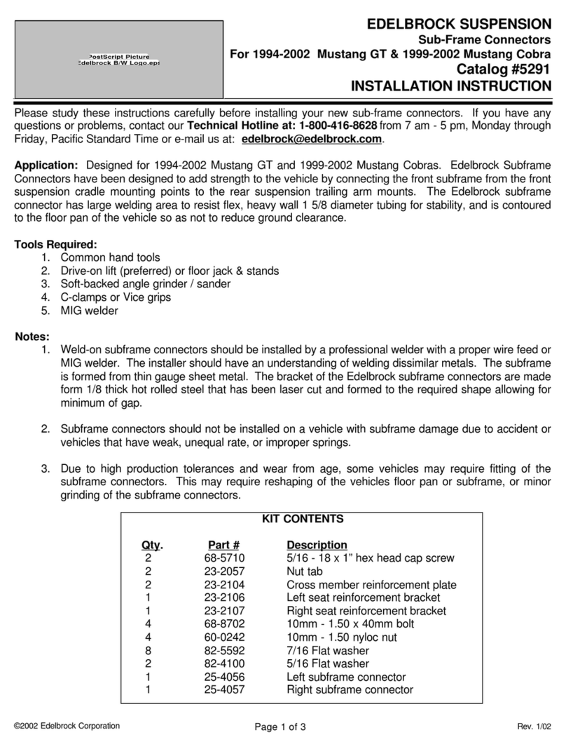
  9. Edelbrock 6883 User manual

Edelbrock 6883 User manual

This manual suits for next models

1

Other Edelbrock Automobile Part manuals

Edelbrock 73802 User manual

Edelbrock

Edelbrock 73802 User manual

Edelbrock 3714 User manual

Edelbrock

Edelbrock 3714 User manual

Edelbrock 70005 User manual

Edelbrock

Edelbrock 70005 User manual

Edelbrock Honda XR400 Owner's manual

Edelbrock

Edelbrock Honda XR400 Owner's manual

Edelbrock 5790 User manual

Edelbrock

Edelbrock 5790 User manual

Edelbrock 4790 User manual

Edelbrock

Edelbrock 4790 User manual

Edelbrock Performer 4754 User manual

Edelbrock

Edelbrock Performer 4754 User manual

Edelbrock 3847/3 User manual

Edelbrock

Edelbrock 3847/3 User manual

Edelbrock 71001 User manual

Edelbrock

Edelbrock 71001 User manual

Edelbrock 5253 User manual

Edelbrock

Edelbrock 5253 User manual

Edelbrock 4737 User manual

Edelbrock

Edelbrock 4737 User manual

Edelbrock 66492 User manual

Edelbrock

Edelbrock 66492 User manual

Edelbrock 6571 User manual

Edelbrock

Edelbrock 6571 User manual

Edelbrock 6661 User manual

Edelbrock

Edelbrock 6661 User manual

Edelbrock 66042 User manual

Edelbrock

Edelbrock 66042 User manual

Edelbrock 68982 User manual

Edelbrock

Edelbrock 68982 User manual

Edelbrock 1400 User manual

Edelbrock

Edelbrock 1400 User manual

Edelbrock 72279 User manual

Edelbrock

Edelbrock 72279 User manual

Edelbrock 66013 User manual

Edelbrock

Edelbrock 66013 User manual

Edelbrock 5672 User manual

Edelbrock

Edelbrock 5672 User manual

Edelbrock 25-9215 User manual

Edelbrock

Edelbrock 25-9215 User manual

Edelbrock Performer RPM 7167 User manual

Edelbrock

Edelbrock Performer RPM 7167 User manual

Edelbrock 2860 User manual

Edelbrock

Edelbrock 2860 User manual

Edelbrock 68003 User manual

Edelbrock

Edelbrock 68003 User manual

Popular Automobile Part manuals by other brands

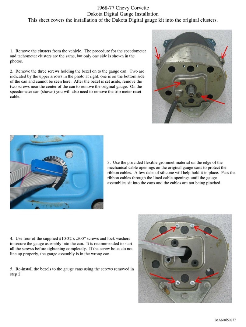
Dakota Digital 650277 Installation

Dakota Digital

Dakota Digital 650277 Installation

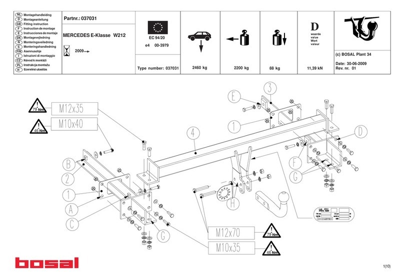
bosal 037031 Fitting instructions

bosal

bosal 037031 Fitting instructions

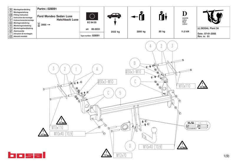
bosal 028091 Fitting instructions

bosal

bosal 028091 Fitting instructions

Vintage Air 571063 manual

Vintage Air

Vintage Air 571063 manual

GFB EX38 instruction manual

GFB

GFB EX38 instruction manual

Dodge 8W-43 Wiring diagram

Dodge

Dodge 8W-43 Wiring diagram

ICI Magnum FBM10DGN Installation

ICI

ICI Magnum FBM10DGN Installation

Volant Perfomance 19435 installation instructions

Volant Perfomance

Volant Perfomance 19435 installation instructions

Robin America DY30 Service manual

Robin America

Robin America DY30 Service manual

Vintage Air 571065 manual

Vintage Air

Vintage Air 571065 manual

AEM 21-724 installation instructions

AEM

AEM 21-724 installation instructions

Havis-Shields Rear Partition w/ Exit Hatch P-REAR-2 installation instructions

Havis-Shields

Havis-Shields Rear Partition w/ Exit Hatch P-REAR-2 installation instructions

Volvo FM 42R B9 HCM Specification sheet

Volvo

Volvo FM 42R B9 HCM Specification sheet

Vintage Air 751170 manual

Vintage Air

Vintage Air 751170 manual

Eibach 2021.312 installation instructions

Eibach

Eibach 2021.312 installation instructions

Gibson 617000 instruction manual

Gibson

Gibson 617000 instruction manual

Gibson 6200 instruction manual

Gibson

Gibson 6200 instruction manual

Toshiba 48-1250 A instruction manual

Toshiba

Toshiba 48-1250 A instruction manual

manuals.online logo
manuals.online logoBrands
  • About & Mission
  • Contact us
  • Privacy Policy
  • Terms and Conditions

Copyright 2025 Manuals.Online. All Rights Reserved.

2.Install supplied exhaust gasket in place between header
and cylinder head. Install one bolt to hold gasket in
place.
3.Install supplied header bolts.T ighten all bolt s evenly.
4. Reinstall clutch cable bracket, spark plugs, plug wires,
and dipstick tube assembly. Do not tighten H-pipe.
NOTE: Bending of clutch cable bracket may be neces-
sary for clearance.
Left side is complete.
NOTE: Use supplied Anti-Seize on all bolt s.Apply liber -
ally to collector socket to ensure proper seal with H-pipe.
• RIGHT SIDE INSTALLATION
1. Remove lower motor mount nut (right side only) and
raise engine approximately 1".
2. Put right side T.E.S. header into position. Then lower
engine block into position and reinstall motor mount nut.
Put H-pipe into position (do not tighten).
3.Install supplied exhaust gasket in place between header
and cylinder head. Install one supplied header bolt to
hold gasket in place.
4.Install supplied header bolts.T ighten all bolt s evenly.
• DISASSEMBLY
1. Raise front of vehicle using the front crossmember to
support the vehicle. Position jack stands under the cross-
member. Drive up ramps may also be used to raise the
front of the vehicle. Make sure parking brake is on and
the rear wheels are blocked so vehicle cannot roll.
2. Loosen H-pipe from stock exhaust headers.
3. Remove the dipstick tube assembly, and clutch cable
bracket from the left side of the engine.
4. Remove air intake tube, air cleaner cover and air flow
sensor from the right side of the engine. Also remove the
smog hoses from the same side.
5. Remove the stock exhaust headers and gaskets. Make
sure the gasket surfaces are clean.
6. Take all the sp ark plugs out, remove plug wire holders
from bolt posts on the valve covers. Label all plug wires
for ease of reassembly.
• LEFT SIDE INSTALLATION
1. Put lef t side Bassani header into position. Jostle H-pipe
to allow header to drop into place. Set H-pipe in place do
not tighten.
© 1997 Edelbrock Corp. REV 1/97
TUBULAR EXHAUST SYSTEM
CATALOG #6883/#7983
1986-1993 Ford Mustang /Mark/Capri with 5.0L V8
Equal Length TES Headers
INSTRUCTIONS
• PLEASE study these instructions carefully before
inst alling your new Tubular Exhaust System (TES). If you
have any questions or problems, do not hesitate to con -
tact our Technical Hotline at : 1-800-416-8628.
• TUBULAR EXHAUST SYSTEM: These components are
designed as a system to improve the exhaust efficiency
of the Ford 5.0L V8 engine. A performance gain can be
expected by the installation of the system. This system
requires no welding for installation and ret ains all O.E.M.
emissions equipment.
• SUGGESTED TOOLS FOR INSTALLATION: This vehi -
cle has some metric fasteners
Sockets- 7/16", 1/2", 9/16", 5/8", 11/16"
Screwdriver- straight blade
Wrenches- 7/16", 1/2", 9/16", 11/16"
W ire cutters
Pliers
Ratchet- 3/8 drive
Extension- about 10"
Universal 3/8 drive
Ratchet- 1/4" drive
Extension- 3-6"
Jackstands, screwdrivers, pliers, crescent
wrench, hacksaw,etc.
Liquid penetrant, (GM #1052627) anti-seize com
pound (GM #5613695)
• WARNING: The use of "Thermal Wrap" materials will
void the warranty on your Tubular Exhaust System.Those
products can cause excessive heat and moisture buildup
resulting in corrosion of the system. If additional thermal
isolation is desired, use the Edelbrock Pro-Tech coated
TES #7983.
• NOTE: The paint used on non-coated T.E.S. (6800 &
6600 series) is for protection during shipping and stor-
age and will burn off soon af ter the engine is st arted.
Those who desire a longer lasting finish should sand
blast the T.E.S. to remove the original paint, then apply
high temperature header paint, such as VHT, available at
most auto part s stores.
• CAUTION: Due to higher underhood temperatures gen-
erated by T.E.S., vehicles equipped with original spark
plug wires should have them replaced with high temper-
ature plug wires for longer life.
• NOTE: When cleaning any Edelbrock Pro-Tech coated
TES, use only soap and warm water.The use of caustic
solvents (Gunk, etc.) will mar or damage the Pro-Tech
coating.
• Please complete and mail your warranty card. Be sure to write the model number of this product in the Part #____
sp ace.
THANK YOU.
1 Manifold left side #25-9107
1 Manifold right side #25-9108
2 Bracket; A.I.R. tube
16 Hex header bolts; 3/8" x 1"
1 Hose clamp; 11/16" 1-1/4"
2 Ford V8 port gaskets
1 Hose; 3/4" x 5-1/2"
1 Hex nut; 1/4"-20
1 Hex bolt; 1/4"-20 x 3/4"
1 A.I.R. tube; zinc plated
1 Lock washer; 1/4"
16 Lock washers; 3/8"
4 Flat washers; 3/8"
• SMOG HOSE ASSEMBLY
1. Use hardware supplied as shown in Figure 1 for smog
hose adaptation
#1 3/4" diameter extension hose, 5-1/2" long.
#2 3/4" diameter bent extension tube.
#3 2-#10 hose clamps.
#4 5/16" x 18 bolt. hex nut, and lock washer.
#5 3" smog tube support bracket.
2. Replace upper stock smog hose (#1) with the one sup-
plied in kit (3/4" I.D. x 5 1/2") using stock clamp s.
3. Cut upper stock smog hose in half to use at each end to
accept (#2) 3/4" diameter bent extension tube (supplied
in kit ) to assemble bottom halt of smog pump. 2 addi-
HARDWARE SUPPLIED
FIGURE 1
tional hose clamps are needed.
4. Tighten clamps on smog hoses. Reinstallairintake tube,
air flow sensor and air cleaner cover.
5. Tighten H-pipe to T.E.S. headers.
6.Start engine and check for any exhaust leaks. If every-
thing is satisfactory, you are ready to go.
7. Check tightness of all header hardware after one day of
operation.
1
2
3
4
5