Edenred UTA MultiBox User manual

UTA MultiBox®
Instruction manual
UTA MultiBox®Manual
Since August 2020 the UTA MultiBox®has a new design. The corresponding manual can be found at the beginning of this
document. The manual of our predecessor follows from page 27 onwards. For questions and suggestions please contact the
UTA Toll Service will be happy to assist you.
UTA MultiBox®NEW DESIGN UTA MultiBox®Predecessor

UTA MultiBox®
Instruction manual

UTA MultiBox®
3
Instruction manual
Content
PREFACE 4
1. Introduction 5
2. Installation of the OBU 6
2.1 Installation of the UTA MultiBox®on an existing battery cable 6
2.2 There is no battery related cable 9
2.3 Position the UTA MultiBox®on the Windscreen 10
3. Connecting the Power Cable 11
4. Connection of the UTA MultiBox®to the Power Supply 12
5. Switching on the UTA MultiBox®13
5.1 Settings & initial activation 14
6. LED Display 17
6.1 Other possibilities 18
7. Error code 19
8. Toll Contexts 20
9. Paying at the Toll Station 21
9.1 Lanes 21
9.2 Drive through at the toll station 22
10. Emergency Plan in Case of Malfunction 23
11. Useful information 25
12. Checklist 26
13. Contact Details 27

UTA MultiBox®
4
Instruction manual
PREFACE
Dear user,
Please read this instruction manual carefully. This is the only way to ensure that the UTA MultiBox®can be made full use of in accor-
dance with the terms of use.
We would like to draw your attention to the fact that the UTA MultiBox®has to be connected to a power supply at all times, even
though it has a battery. Updates and the smooth functioning of the On-Board Unit (also called “OBU”) can only be ensured if the
device is continuously connected to a power supply via the supplied hardware.
These instructions explain to you step by step how to install and start up the OBU as well as other important details about its use. To-
gether with the manual for drivers you will be perfectly prepared and learn all about the important details of the UTA MultiBox®. The
driver manual also contains useful basic information and practical tips, for example what you do at the toll plazas and which lane
you should take. There is a check list on the last page that tells you what you need to do before you start your trip.
Please note that there are legal implications associated with reading this instruction manual (see terms of use).
UTA assumes no liability for any malfunctions that are the result of non-compliance with the instructions.
We hope that you have a good trip with the UTA MultiBox®!

UTA MultiBox®
5
Instruction manual
1. Introduction
A = OBU
B = Holder
C = Power cable
D = Aluminium-coated shipping bag (storage/returns)
The aluminium coating of the shipping bag ensures that all OBU services and functions are stopped
and no transactions are generated during transport.
Please note that the box covers several toll networks and, depending on the options you have
selected, allows you to do the following:
• Toll payment in France, Portugal, Spain, Liefkensoektunnel (BEL), Herrentunnel (DE)
• Optional Viapass network activation (BEL)
• Optional use of the UTA MultiBox Manager
Please note that you must connect and activate the UTA MultiBox®in order to use all the services you have subscribed to.
The information stored on the box must be consistent with the data of the vehicle in which it is installed.
The device must be constantly supplied with power and be switched on. All subscribed networks must be displayed and the stored data must match
the data of the respective vehicle.
UTA shall not be held responsible in the event of improper installation and/or use of the device and/or if the box is damaged.

UTA MultiBox®
6
Instruction manual
2. Installation of the OBU
2.1 Installation of the UTA MultiBox®on an existing battery cable
1. Remove the connection cable cover by
pulling it.
2. Remove the connection cable from the
docking station.

UTA MultiBox®
7
Instruction manual
2.1 Installation of the UTA MultiBox®on an existing battery cable
3. Use the cable
connected to your
battery to replace
it.
4. Place the end of the
connection cable in the
docking station. The arrow
on the end cap must show
towards you.
5. Push the end of
the connection ca-
ble completely into
the docking station.
6. Push the cover in until
you hear a „click“.

UTA MultiBox®
8
Instruction manual
8. Stickers for one-time use!
Place the UTA MultiBox® on the docking
station. Check that the OBU is correctly
connected. To do this, you must see
information on the screen.
2.1 Installation of the UTA MultiBox®on an existing battery cable
7. The bracket with cable should look like in
the picture.

UTA MultiBox®
9
Instruction manual
2.2 There is no battery related cable
1. Take the UTA
MultiBox®and the
holder to hand.
2. Drücken Sie die
Abdeckung hinein,
bis Sie ein „Klick“ hören.
4. Stickers for one-time use!
Place the UTA MultiBox®on
the docking station.
Check that the OBU is
correctly connected. To do
this, you must see the
Information on the screen.
3. Push the cover
in until you hear a
„click“.

UTA MultiBox®
10
Instruction manual
2.3 Position the UTA MultiBox®on the Windscreen
Position the OBU at the bottom in the middle of the clean windscreen on the inside (outside the
tinted area). There must be a free space of about 10 cm all around the OBU.
The driver must remove any objects that could interfere with the operation of the OBU.
UTA MultiBox®
11
Instruction manual
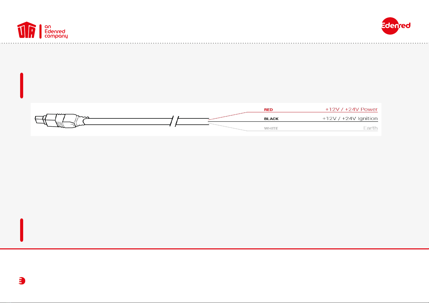
3. Connecting the Power Cable
To use the OBU, it has to be connected to the power supply using the supplied cable. This is the only way to ensure that toll
collection and the uploading of updates work properly. Connection via a USB cable or a cigarette lighter adapter is not
permitted.
• Measure the cable length from the OBU plug to the vehicle power supply and then cut off the plug for the cigarette lighter and
the excess length of the cable.
• Use the diagram above to locate the connection points in the vehicle. The black wire for the switch-on signal must be
connected to the ignition of the vehicle.
• Install a 5A fuse (not included) in series with the supply wires (red and black wires) before connecting the cables to the vehicle.
If the vehicle is already connected to a power supply, this step is not necessary.
•Finally, connect all wires to the previously identied connection points (vehicle supply, ignition and ground).
The UTA MultiBox®must be installed by a specialist company. Failure to comply with these instructions means that UTA assumes
no liability in the event of a complaint.
UTA MultiBox®
12
Instruction manual
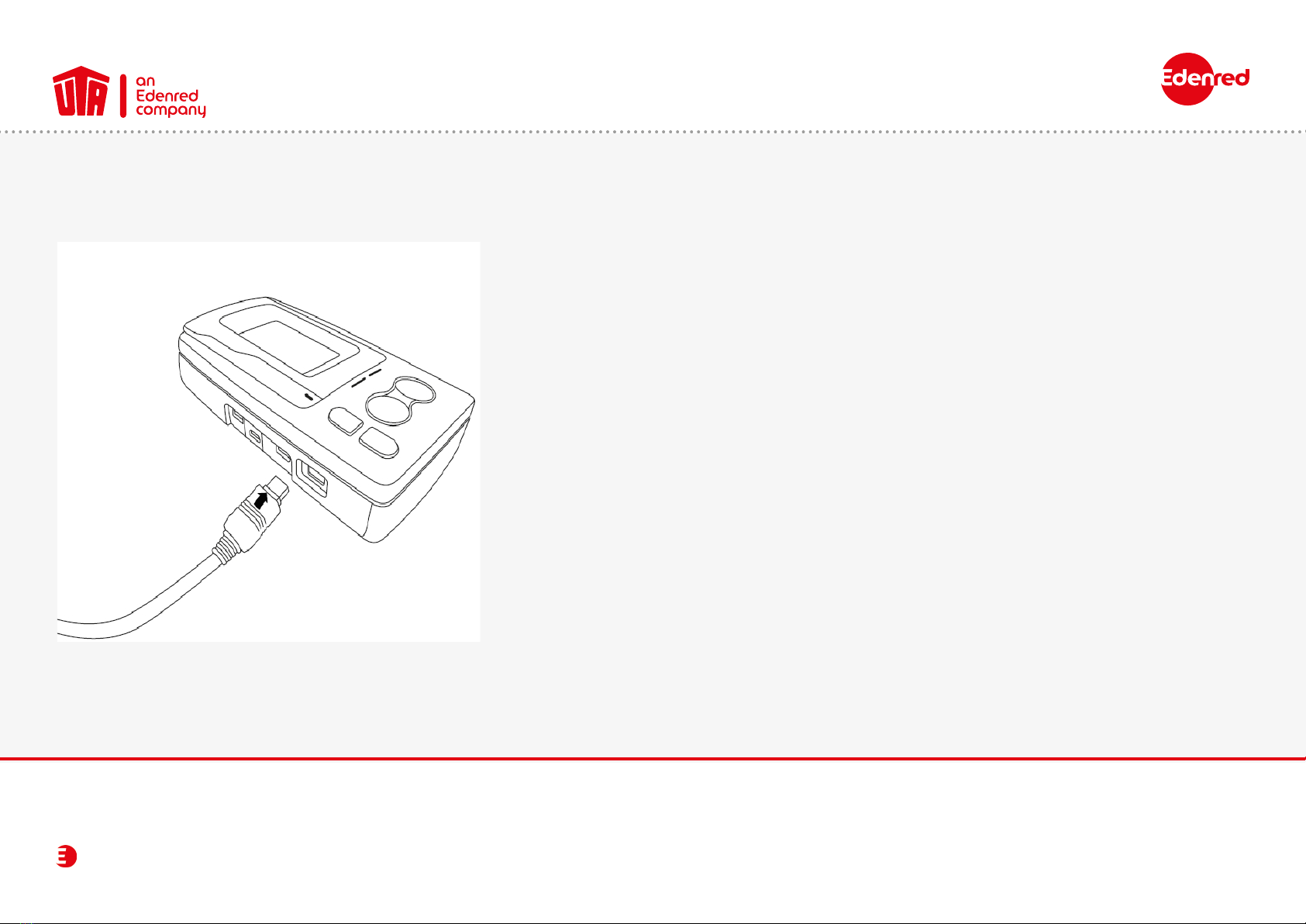
4. Connection of the UTA MultiBox®to the Power Supply
• Remove the OBU from the bracket attached to the windscreen
by pressing the plastic tab on the bracket.
• Connect the OBU to the connecting cable and then to the
power supply. Press rmly until you hear a click sound.
• This connection must be made for the UTA MultiBox®to work
properly.
• Then put the OBU back into the bracket.
• Make sure that the OBU is connected correctly. To do this, read
the information on the screen. If it is not connected, repeat
step 2 in this chapter.

UTA MultiBox®
13
Instruction manual
5. Switching on the UTA MultiBox®
1. Double click to see the menu.
2. You navigate the menu using the arrows.
3. Press this button to exit the menu.
The buttons do not work at speeds above 10 km/h.
13
2
UTA MultiBox®
14
Instruction manual
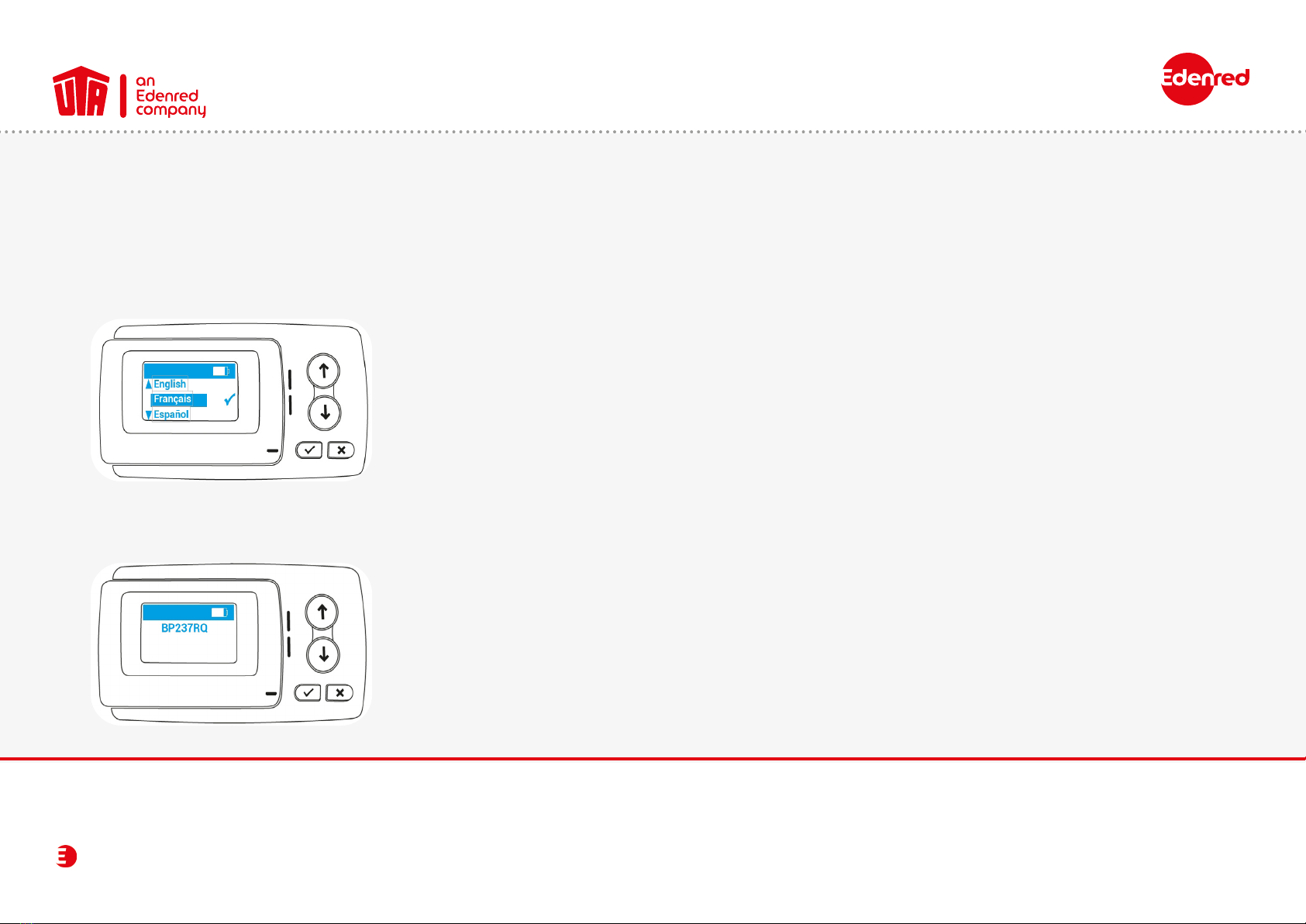
5.1 Settings & initial activation
• Power supply: Connect the OBU to the power supply.
• Language settings: Use the arrows to select the language of the menu and conrm your selection by clicking on the
tick. The default language is English.
List of available languages:
• English
• French
• Spanish
• German
• Italian
• Dutch
• Polish
• Portuguese
• Czech
• Registration number check: Make sure the registration number on the display matches your vehicle’s registration number.
UTA MultiBox®
15
Instruction manual
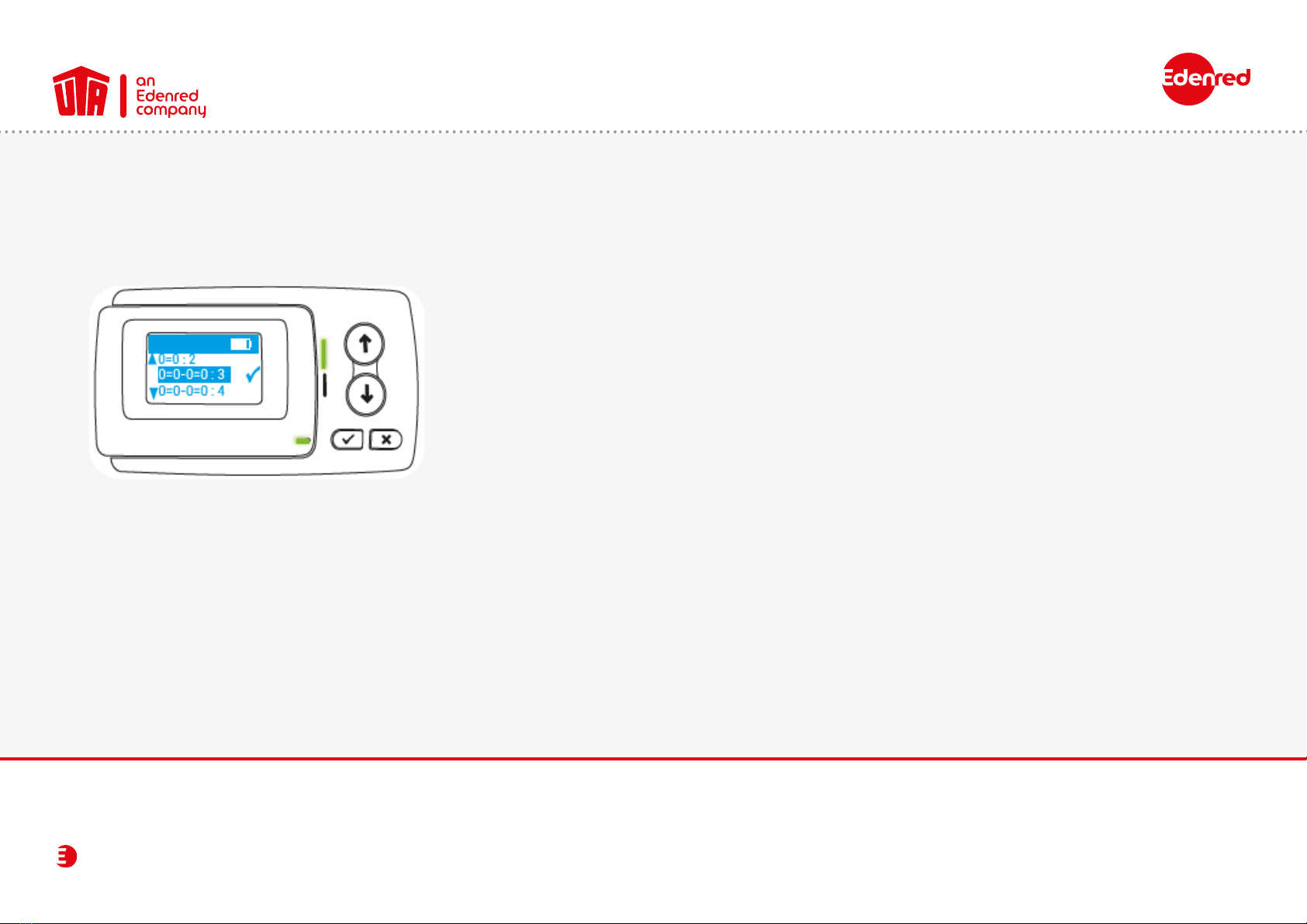
5.1 Settings & initial activation
• Change the number of axles according to your vehicle combination and nally conrm your choice by pressing
the check mark.
Without trailer: 0=0:2 (vehicle with 2 axles)
With trailer: 0=0-0=0:4 (vehicle with 4 axles)
•Conrm the weight with the check mark. By default, the weight saved in the OBU corresponds to the permissible
total weight.
Example: Your vehicle combination consists of a truck and trailer with a total of 5 axles: 0=0-0=0:5+.

UTA MultiBox®
16
Instruction manual
5.1 Settings & initial activation
The device is now switched on. The green LED indicates that the vehicle device is now ready for operation.
Your OBU will now operate
when you start the engine
of your vehicle next time.
If the LED lights up red or
the display shows an error
message, then the UTA
MultiBox®is not ready for
use. Please contact UTA
immediately.
Contact UTA immediately if the following information is incorrect:
• Registration number
• Euro emission class
• Permissible total weight of the vehicle
• Number of axles of the tractor unit
Please note: any false information results in a penalty or forfeiting of the discount.
UTA MultiBox®
17
Instruction manual
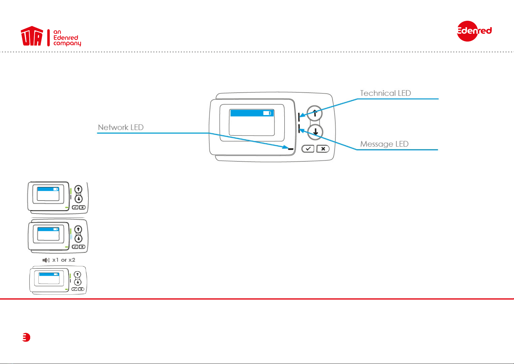
6. LED Display
The technical and network LEDs light up green.
Your vehicle device is ready for operation.
On the toll networks in France, Spain, Portugal, Liefkenshoek (Belgium) and Herrentunnel (Germany),
the onboard unit emits a beep (1 or 2 beeps) as soon as it is detected while passing through a station.
The LED message lights up white. You have received a message.
Look in your messages at the next stop. To do so, click on the check mark.

UTA MultiBox®
18
Instruction manual
6.1 Other possibilities
The technical LED lights up green and ashes. The OBU detects a temporary problem.
Stop and see what the error message on the screen means (chapter Error message).
The power LED is permanently lit in orange. You may be in a toll network that is not active on your OBU. Stop the vehicle. Look
up the error messages on the screen and refer to the chapter Error message.
The technical and network LEDs light up permanently red. The vehicle device detects a serious problem. Stop the vehicle and
contact your UTA contact person immediately.
None of the LEDs are lit. Your vehicle unit is not ready for operation. Stop and check the power supply to your
Vehicle device. If the problem persists, please contact your UTA contact person.
If your vehicle device did not emit a beep or emits 4 in succession, the transaction was not conrmed.
You are not travelling in accordance with the regulations. Please refer to chapter 10.

UTA MultiBox®
19
Instruction manual
7. Error code
Error code Meaning Now what?
20026 The unit has detected a power supply problem. Stop the vehicle. Check the power supply to your unit.
1003 The unit has detected a temporary problem.
GPS reception is disturbed. Stop the vehicle. If the problem persists after 15 minutes, contact the hotline.
12003 The unit has detected a temporary problem. Stop the vehicle. If the problem persists after 15 minutes, contact the hotline.
1031
The message is generally displayed in Germany and Belgium if the
toll context is not activated. Near the border, this message is also
displayed.
If another toll device is in use that covers the toll context, the error message can be
ignored. Otherwise, please contact your contact person.
20037 The unit has detected a payment problem with your journey. Stop and get in touch with your contact person.
11004 The unit detects a critical error.
Your OBU is not operational. Stop and get in touch with your contact person.
12004 The unit detects a critical error.
Your OBU is not operational.t. Stop and get in touch with your contact person.
10020 Your unit has been exposed to extreme temperatures. Stop and get in touch with your contact person.
20034 Your unit is not operational. Stop and check the power supply to your vehicle device. If the problem persists,
get in touch with your contact person.
10006 Your unit is not operational. Stop and check the power supply to your vehicle device. If the problem persists,
get in touch with your contact person.
In the event of a problem, you can reach us at the following telephone numbers:
UTA Toll Service
+49 6027 509-617
Monday - Friday 8.00 a.m. - 18.00 p.m.
In the Belgian “Viapass” network
+33 (0)4 26 29 75 80
Available around the clock!

UTA MultiBox®
20
Instruction manual
8. Toll Contexts
BE LIEFKENSH. Belgium
BE VIAPASS Belgium
DE HERRENTUN. Germany
ES VIA-T Spain
FR TIS-PL France
PT VIA VERDE Portugal
To check in which countries your OBU can be used and is activated for, go to the “networks” tab in the menu.
Press Xto exit the menu.
Table of contents


