Edge EDGE-1830 User manual
Original Service Manual CD-941-510-2
EDGE-1830, EDGE-2440, EDGE-3240, EDGE-2460, EDGE-3260,
EDGE-3860, EDGE-4460, EDGE-3270, EDGE-3870
GENERATION 2
-BYPASS SYSTEM-
ORIGINAL SERVICE MANUAL
NORTH AMERICA
RETAIN THIS MANUAL FOR FUTURE REFERENCE
TO BE SERVICED BY AUTHORIZED PERSONS ONLY
MF&B RESTAURANT SYSTEMS, INC.
119 ICMI ROAD, DUNBAR, PA 15431, USA
TF: 1 (888) 480-EDGE
P: 1 (724) 628-3050 F: 1 (724) 626-0247
Email: SUPPORT@EDGEOVENS.COM
WWW.EDGEOVENS.COM
REVISION 4.1, Jan 2021

EDGE-1830 / EDGE-xx40 / EDGE-xx60 / EDGE-xx70
Original Service Manual ii Rev 4.1, January 2021
LEGAL INFORMATION
Copyright 2021 MF&B Restaurant System, Inc. All rights are reserved. To support the intended
use of the product described in this publication, the purchaser of the product is permitted to
copy this publication, for internal distribution only, from the media provided by MF&B
Restaurant Systems, Inc. No other use, reproduction, or distribution of the publication, or any
part of it, is permitted without written permission from MF&B Restaurant Systems, Inc. All rights
are reserved.
Caution MF&B Restaurant Systems, Inc. assumes no responsibility for any injury, or for any
illegal or incorrect use of the product, that may result from failure to use this product in
accordance with the instructions, cautions, warnings, or indications for use published in this
manual.
Software incorporated in this product is copyright protected by MF&B Restaurant Systems or
its vendors. All rights are reserved. The software is protected by United States of America
copyright laws and international treaty provisions applicable worldwide. Under such laws, the
licensee is entitled to use the copy of the software incorporated within this instrument as
intended in the operation of the product in which it is embedded. The software may not be
copied, decompiled, reverse-engineered, disassembled or otherwise reduced to human-
perceivable form. This is not a sale of the software or any copy of the software; all right, title
and ownership of the software remains with MF&B Restaurant Systems, Inc., or its vendors.
Modifications to the EDGE Oven, not expressly approved by MF&B Restaurant Systems, Inc.
may void the purchaser’s authority to operate the equipment.
For information about any EDGE Ovens product, contact MF&B Restaurant Systems, Inc.,
Technical Support or visit www.edgeovens.com.
ALL WARRANTY SERVICE MUST BE PRE-AUTHORIZED BY MF&B OR AN APPROVED
REPRESENTATIVE WITHIN THE DESTINATION REGION. ANY UNAUTHORIZED SYSTEM
DIAGNOSTIC, SERVICE FEES, TRAVEL FEES, PART AND LABOR WILL BE THE
RESPONSIBILITY OF THE APPLIANCE OWNER/OPERATOR. ADDITIONALLY, UNAUTHORIZED
SERVICE WILL VOID ALL EXPRESSED WARRANTIES ON THE PRODUCT. PLEASE CALL FOR
ASSISTANCE AND CONSULT THE WARRANTY POLICY WITHIN THE INSTALLATION AND
OPERATION INSTRUCTIONS FOR COMPLETE DETAILS.
MF&B Restaurant Systems, Inc.
119 ICMI Road
Dunbar, PA 15431-2309, USA
Tel: +00 (1) 724.628.3050
Fax: +00 (1) 724.626.0247

EDGE-1830 / EDGE-xx40 / EDGE-xx60 / EDGE-xx70
Original Service Manual iii Rev 4.1, January 2021
Table of Contents
1. SAFETY INFORMATION ________________________________________________________________ 1
❖Purpose of this manual _____________________________________________________________________ 1
❖Service policy _____________________________________________________________________________ 1
❖Symbols _________________________________________________________________________________ 2
❖General Warnings _________________________________________________________________________ 2
❖Warnings related to the operating environment_________________________________________________ 2
❖Warnings related to electric shock ____________________________________________________________ 2
❖Warnings related to hot surfaces _____________________________________________________________ 2
❖General Cautions __________________________________________________________________________ 2
❖Electrostatic discharge (ESD)_________________________________________________________________ 3
2. General Operation (Firmware MC:33, UI:33) _______________________________________________ 4
❖Menu System Overview ____________________________________________________________________ 4
❖Basic Operation ___________________________________________________________________________ 4
❖Advanced Operation _______________________________________________________________________ 5
❖Service Operation _________________________________________________________________________ 9
3. Tools Required for Service _____________________________________________________________ 10
❖Instruments _____________________________________________________________________________ 10
❖Tools___________________________________________________________________________________ 10
❖Supplies ________________________________________________________________________________ 10
4. Sequence of operations (Modulating) ___________________________________________________ 11
❖Electrical supply__________________________________________________________________________ 11
❖MAIN POWER switch______________________________________________________________________ 11
❖Touch POWER Icon _______________________________________________________________________ 11
❖Ignition Module and Valve Operation ________________________________________________________ 11
❖High limit prevention______________________________________________________________________ 12
❖Cool down ______________________________________________________________________________ 12
5. System setup (Bypass) ________________________________________________________________ 13
❖Orifice__________________________________________________________________________________ 13
❖Air shutter ______________________________________________________________________________ 13
❖Combination gas valve ____________________________________________________________________ 13
➢Valve Specifications________________________________________________________________________________ 13
➢Pressure Taps and Regulator ________________________________________________________________________ 14
➢Gas Pressures ____________________________________________________________________________________ 14
➢Manifold Adjustment ______________________________________________________________________________ 14
❖Circulation fan speed (VFD Adjustment) ______________________________________________________ 15

EDGE-1830 / EDGE-xx40 / EDGE-xx60 / EDGE-xx70
Original Service Manual iv Rev 4.1, January 2021
6. Gas conversion (Bypass) ______________________________________________________________ 16
❖Removing the Gas Train ____________________________________________________________________ 16
❖Replacing the Main Orifice__________________________________________________________________ 16
❖Replacing the Pilot Orifice __________________________________________________________________ 16
❖Replacing the Gas Valve ____________________________________________________________________ 17
❖Installing the Gas Train_____________________________________________________________________ 17
❖Adjustment Air Shutter ____________________________________________________________________ 17
❖Markings ________________________________________________________________________________ 18
7. Troubleshooting_____________________________________________________________________ 19
❖Basics First_______________________________________________________________________________ 19
❖G2 ‘DIAGNOSTIC’ Lamp ____________________________________________________________________ 20
❖G2 Control System Messages________________________________________________________________ 21
❖Troubleshooting flowcharts _________________________________________________________________ 24
➢Ignition Module, Diagnostic LEDs _____________________________________________________________________ 24
➢Control System, Diagnostic Messages (1 of 2) ___________________________________________________________ 25
➢Control System, Diagnostic Messages (2 of 2) ___________________________________________________________ 26
8. Part failure verification _______________________________________________________________ 27
❖Controls and assemblies____________________________________________________________________ 27
➢Switches _________________________________________________________________________________________ 27
➢Fuses / Fuse holder ________________________________________________________________________________ 27
➢Cooling Fan_______________________________________________________________________________________ 27
➢Main Valve Coils___________________________________________________________________________________ 27
➢Optical Flame Detector _____________________________________________________________________________ 28
➢Ignition Electrodes / Flame Rod ______________________________________________________________________ 28
➢Burner Blower Motor (Induction) _____________________________________________________________________ 28
➢Transformer ______________________________________________________________________________________ 28
➢Conveyor Motor___________________________________________________________________________________ 28
➢Air Switch ________________________________________________________________________________________ 29
➢Thermocouple ____________________________________________________________________________________ 29
➢Variable Frequency Drive ___________________________________________________________________________ 29
➢Main Fan, Motor (3PH, 3/4HP) _______________________________________________________________________ 29
9. Wiring Diagram _____________________________________________________________________ 30
10. Type-J thermocouple chart __________________________________________________________ 31
❖Thermocouple Worksheet __________________________________________________________________ 32
11. Part List__________________________________________________________________________ 33
12. Revision history ___________________________________________________________________ 34

EDGE-1830 / EDGE-xx40 / EDGE-xx60 / EDGE-xx70
Original Service Manual 1 Rev 4.1, January 2021
1. SAFETY INFORMATION
All service technicians of the EDGE Oven must read this summary and all warnings and cautions in the
manual.
Any internal part(s) replacement or assembly and reassembly must be performed by qualified service
personnel with a good understanding of mechanical, gas and electrical components. If difficulties arise
in locating a qualified service person, please contact your EDGE oven distributor or MF&B for
assistance in locating qualified personnel to assist you.
❖Purpose of this manual
The purpose of this manual is to assist with common troubleshooting scenarios and provide a quick
reference guide for service providers. The information within this document is not intended for
customers or the inexperienced.
❖Service policy
All repairs on products within the warrantyperiod must be PRE-AUTHORIZED by MF&B Restaurant
Systems, Inc., or an approved representative within the destinated region. Unauthorized repairs
will not be reimbursed. Modifications will void the warranty. Consult the WARRANTY POLICY
within the Installation and Operation Instructions for complete details.
If the product fails to function correctly—or if you need assistance, service, or spare parts—contact
MF&B Restaurant Systems, Inc.
Before contacting MF&B Restaurant Systems,Inc., try to duplicate the problem, and check electrical
outlets and gas supply lines to ensure that they are not causing the problem. When calling, please
be prepared to provide:
• Supplier, model number, and serial number of your product.
• Complete description of the problem.
• Complete name, address, and phone number of your facility.
• For out-of-warranty repairs or spare parts orders, a purchase order (or credit card) number.
• For parts orders, the required spare or replacement part numbers.
If your product requires warranty, or non-warranty repair service, please call MF&B Restaurant
Systems, Inc. first. A representative will assist you troubleshooting the problem and will make every
effort to solve it over the phone, avoiding potential unnecessary expenses and downtime.
In case a service call cannot be avoided, the representative will record all necessary
information and may attempt to coordinate the delivery of repair parts with a servicer in your area.
Repair parts which are not used and/or replaced parts should be returned to MF&B Restaurant
Systems, Inc.
To aid in quick service and to accommodate the servicers needs, ensure the product is accessible
and that there is ample clearance for the product to be disconnected and rotated as needed.
Due to the size of the product and the size of the product parts, a servicer may require assistance
with some handling or maneuvering or this product or product parts. Please use care and correct
lifting techniques.

EDGE-1830 / EDGE-xx40 / EDGE-xx60 / EDGE-xx70
Original Service Manual 2 Rev 4.1, January 2021
❖Symbols
WARNING Indicates conditions that could lead to injury or death.
CAUTION Indicates conditions that could damage equipment or property.
CAUTION Indicates conditions that may result in a burn injury.
❖General Warnings
Warnings indicate conditions or practices that could lead to injury or death.
❖Warnings related to the operating environment
WARNING To avoid a possible explosion, do not service the product in an atmosphere where
explosive gases or fuel vapors are present. Verify all gas valves are in the OFF position and
that enough ventilation is present to evacuate any unburnt gases.
❖Warnings related to electric shock
WARNING Electricity can seriously injure or kill. Disconnect the power cord for the electrical
outlet or lock out the service disconnect before servicing this equipment. Always ensure an
earth ground is correctly connected to the equipment. When troubleshooting live electrical
circuits, use care and best practices to ensure an electrical pathway is not completed through
the body.
❖Warnings related to hot surfaces
WARNING Seriously injures may occur from contact to hot surfaces. Allow adequate cooling
time of the appliance prior to service or maintenance. In situations where handling of the
appliance or its parts in unavoidable, use thermal protective gloves to protect the hands, wear
long shirts and pants to protect arms and legs. Do not attempt to “test” the temperature of
surfaces by touch.
❖General Cautions
Cautions indicate conditions or practices that could damage the equipment or other correctly.
CAUTION To prevent possible damage, do not use sharp or hard objects on interface screen,
use only fingertips.
CAUTION Mobile RF communications equipment and high frequency LED lighting may affect
the performance of this equipment as dictated by FCC regulations.
CAUTION The power cord must be disconnected from the AC power before cleaning,
maintaining, servicing, or transporting.
CAUTION The gas supply line must be disconnected from the oven before cleaning,
maintaining, servicing, or transporting.
CAUTION There are NO parts of the oven that are designed to withstand impacts. Damage
will result.

EDGE-1830 / EDGE-xx40 / EDGE-xx60 / EDGE-xx70
Original Service Manual 3 Rev 4.1, January 2021
❖Electrostatic discharge (ESD)
CAUTION Electrostatic discharge (ESD) can damage or destroy electronic components.
Handle static-sensitive components using safe practices.
CAUTION Assume that all electrical and electronic components of the appliance are
static sensitive.
Electrostatic discharge is a sudden current flowing from a charged object to another objector to ground.
Electrostatic charges can accumulate on common items such as foam drinking cups, cellophane tape,
synthetic clothing, untreated foam packaging material, and untreated plastic bags and work folders, to
name only a few.
Electronic components and assemblies, if not correctly protected against ESD, can be permanently
damaged or destroyed when near or in contact with electrostatic charged objects. When you handle
components or assemblies that are not in protective bags and you are not sure whether they are static-
sensitive, assume that they are static-sensitive and handle them accordingly.
• Always use techniques to protect personnel and equipment from electrostatic discharge.
➢ESD Wrist or Heal strap (recommended for appliance and personal safety)
• Remove static-sensitive components and assemblies from their static-shielding bags only when you
are stationary and prepared to immediately install the component.
• Remove / install static-sensitive components andassemblies only with appliance power disconnected.
• Insert and seal static-sensitive components and assemblies into their original static-shielding bags.
• Always test your ESD strap before beginning any disassembly or assembly procedures.
EDGE-1830 / EDGE-xx40 / EDGE-xx60 / EDGE-xx70
Original Service Manual 4 Rev 4.1, January 2021
2. General Operation (Firmware MC:33, UI:33)
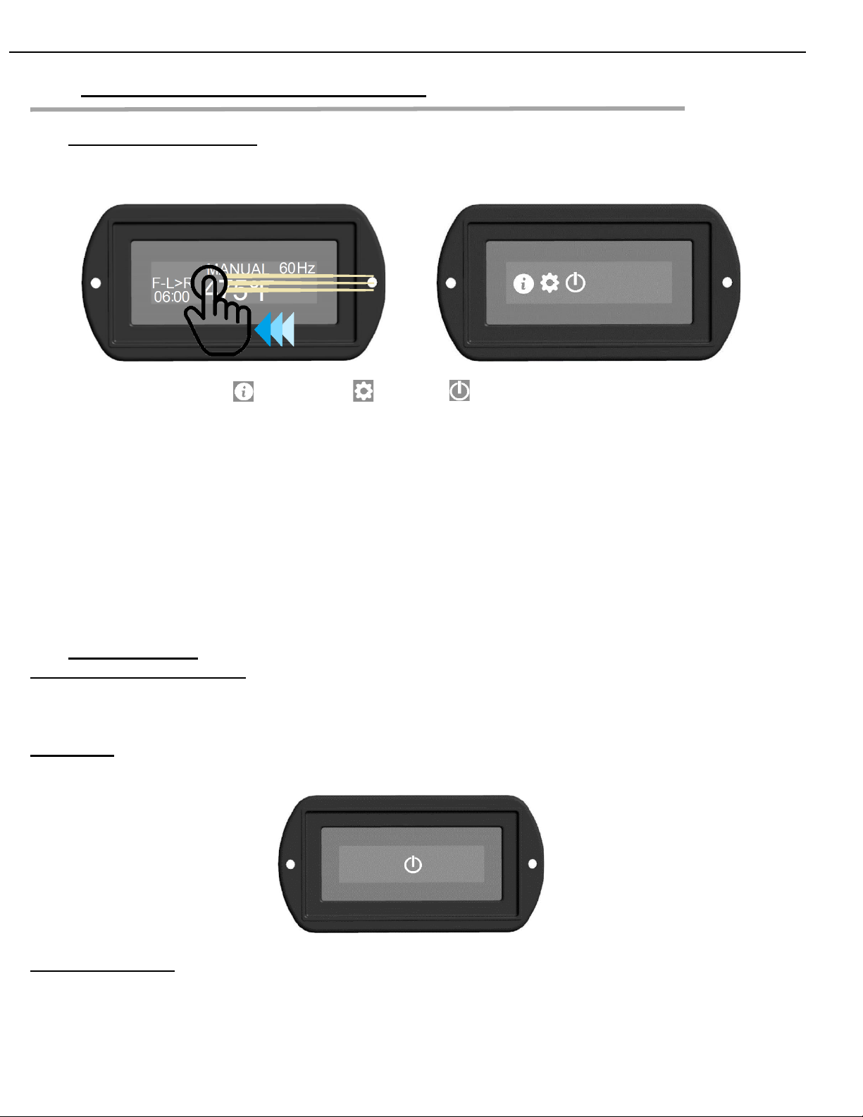
❖Menu System Overview
Additional operation features are found in the Menu System. To access this menu, touch and swipe
the display screen, Left or Right.
The menu icons are: Information, Settings, Power
- Information: The information menu is useful for viewing Alarm history, Software version, Serial
number, Build date, System voltage, Belt demand, iHeat information and for Exporting Logged data
files.
- Settings: The CUSTOMER level Settings Menu provides access to Units of Measurement, Customer
PIN setup, Belt Direction, Software Updating, and Recipe Download/Upload. This menu is protected
by the Customer PIN.
- Power: Touching the Power icon will simply place the oven into Cool Down mode, following a few
seconds of delay. The oven fans will continue to run until the oven temperature falls below 223F /
106C. Normal operation can be resumed by touching and holding the Power icon on the cooldown
screen.
❖Basic Operation
Control Use and Cleaning: The EDGE G2 display is a “touch” screen. Do not strike or impact the
screen with hard objects. Clean with a lightly dampened cloth, do not directly spray the display with
cleaning solutions or water.
Power Up: Power up and starting the oven system is performed by turning the POWER switch to the
ON position. Allow 5 seconds for the system to power up. Touch the power icon on the display.
Operation basics: Basic oven operation is adjustment of bake Temperature adjustment, bake time
adjustment, and main Fan Speed (Hz). While in MANUAL recipe mode (see Advanced Operation for
instructions to Change Recipe), touch the temperature, the adjustment screen will appear.

EDGE-1830 / EDGE-xx40 / EDGE-xx60 / EDGE-xx70
Original Service Manual 5 Rev 4.1, January 2021
Touch the UP/DOWN arrows to adjust the temperature. Touch the CHECK to accept or the X to cancel.
Repeat this method for Time and for the Fan Speed (Hz).
❖Advanced Operation
Change Recipe:
- Touch and hold the recipe namespace on the display for 1-2 seconds.
- Select the desired recipe using the UP/DOWN arrows, touch CHECK to accept.
-*Special items in this menu are:
- ‘<NEW>’ used to define a new recipe based on the current setting of ‘MANUAL’
- ‘MANUAL’ is a “test and tune” mode, allows easy adjustment of the baking parameters
CUSTOMER PIN is required (see CUSTOMER PIN).
Create a New Recipe:
- Define the new recipe in ‘MANUAL’ operation mode.
- Touch and hold the on-screen ‘MANUAL’ namespace for 1-2s.
- Select ‘<NEW>’ from the menu, CUSTOMER PIN is required.
- Define the recipe name (See Recipe NAMESPACE).
- Define/Verify Temp, Time, and Hz (60 is standard).
You may store up to 30 recipes. MANUAL mode is primarily for tuning a recipe, although unsecure,
the oven may be operated in this mode without ever defining a recipe.
Change a Recipe:
- Selecting the recipe (see Change Recipe).
- Touch and hold the recipe namespace on the display until a PIN entry screen appears.
Customer PIN is required.
- Advance through the parameters (Namespace, Temp, Time, Hz), adjustment as needed.
Deleting a Recipe:
- Selecting the recipe (see Change Recipe).
- Touch and hold the recipe namespace on the display until a PIN entry screen appears.
Customer PIN is required.
- In the Namespace adjustment, select ‘<DEL RCP>’.
- The control will default to ‘MANUAL’.

EDGE-1830 / EDGE-xx40 / EDGE-xx60 / EDGE-xx70
Original Service Manual 6 Rev 4.1, January 2021
Customer PIN: (also see CHANGE PIN)
- Touch each digit to adjust from 0-9.
- Adjust the value using the UP/DOWN arrows.
- When the pin is correct, touch the CHECK to accept or X to cancel without storing.
Recipe NAMESPACE:
- UP/DOWN (Orange box) arrows adjust the value of the alpha-numeric character (Red circle)
- To select the alpha-numeric character, touch it (Red Circle). This will advance to the next
character selection.
- Namespaces may be 8 characters long.
- When you complete the Namespace, touch the CHECK (Green box).
The X will cancel without storing any changes.
Temp:
- Use the UP/DOWN arrows to change the temperature value. (350F –600F, 177C –316C)
- When the temperature is correct, touch the CHECK to accept or X to cancel without storing.
Time:
- Use the UP/DOWN arrows to change the time value (03:00 –30:00).
- When the time is correct, touch the CHECK to accept or X to cancel without storing.
Hz: - Use the UP/DOWN arrows to change the VFD Frequency Hz (52 –68).
- When the Hz adjustment is correct, touch the CHECK to accept or X to cancel without storing.

EDGE-1830 / EDGE-xx40 / EDGE-xx60 / EDGE-xx70
Original Service Manual 7 Rev 4.1, January 2021
Belt Direction:
-*Belt direction AND finger pattern are a matched item. Reversing the direction of belt travel
often involves reversing the finger pattern in the oven.
- Swipe the control screen Left or Right to access the Menu System.
- Touch the GEAR icon to enter the Settings Menu, Customer PIN is required.
- Select ‘CUSTOMER’.
- Use UP/DOWN arrows to navigate to ‘BELT’, select.
- Select ‘FRONT DIR’.
- Select ‘L to R’ or ‘R to L’ to change the belt direction.
- Repeat for ‘REAR DIR’ if equipped with a split-belt system.
Units:
- Swipe the control screen Left or Right to access the Menu System.
- Touch the GEAR icon to enter the Settings Menu, Customer PIN is required.
- Select ‘CUSTOMER’.
- Select ‘DISPLAY’.
- Use UP/DOWN arrows to navigate to ‘UNITS’, select.
- Select ‘C’ or ‘F’ to change the units of measurements.
Change Pin:
-*This action will change the default Customer PIN. Default is 0000. Please remember this pin
for future use. If lost or forgotten, please contact MF&B for assistance.
- Swipe the control screen Left or Right to access the Menu System.
- Touch the GEAR icon to enter the Settings Menu, Customer PIN is required.
- Select ‘CUSTOMER’.
- Use UP/DOWN arrows to navigate to ‘PIN SET’, select.
- Touch each digit to adjust from 0-9.
- Adjust the value using the UP/DOWN arrows.
- When the pin complete, touch the CHECK to accept or X to cancel without storing.
Software Update:
-*Updates are available from https://edgeovens.com/support
- Follow the ‘Firmware Update Instructions’ which are also available for download.
Verify the software has installed correctly, see “Software Version Identification”.
Software Version Identification:
To view the current software installed in the oven:
- Swipe the control screen Left or Right to access the Menu System.
- Touch the INFORMATION icon to enter the Information Menu.
- Use UP/DOWN arrows to navigate to ‘UI VERSION’, select.
The UI version will be displayed. *If updated, this number will match the number in the “ui##”
portion of the filename you installed.
To view the MC version, return to the Information menu.
- Use UP/DOWN arrows to navigate to ‘MC VERSION’, select.
The MC version(s) will be displayed. * If updated, this number will match the number in the
“mc##” portion of the filename you installed.
If equipped witha split-belt system, MC1and MC2 will be shown. If thesenumbers donot match,
please perform the software update process again.

EDGE-1830 / EDGE-xx40 / EDGE-xx60 / EDGE-xx70
Original Service Manual 8 Rev 4.1, January 2021
Recipe Download:
-*This feature will save the recipes stored within the control system on a USB Thumb drive.
- Remove the USB dust cover, located near the control cabinet, cooling fan.
- Insert a USB thumb-drive in the USB connector.
- Swipe the control screen Left or Right to access the Menu System.
- Touch the GEAR icon to enter the Settings Menu, Customer PIN is required.
- Select ‘CUSTOMER’.
- Use UP/DOWN arrows to navigate to ‘SYSTEM’, select.
- Use UP/DOWN arrows to navigate to ‘RECIPE DOWNLOAD’, select.
-*The file will be transferred very quickly (< 1s). When the control screen returns to the
DOWNLOAD screen, the process is complete.
- Remove the thumb-drive and install the dust cover over the USB port.
Recipe Upload:
-*This feature will load the recipes stored on a USB Thumb drive to the control system.
- Remove the USB dust cover, located near the control cabinet, cooling fan.
- Insert a USB thumb-drive in the USB connector.
- Swipe the control screen Left or Right to access the Menu System.
- Touch the GEAR icon to enter the Settings Menu, Customer PIN is required.
- Select ‘CUSTOMER’.
- Use UP/DOWN arrows to navigate to ‘SYSTEM’, select.
- Use UP/DOWN arrows to navigate to ‘RECIPE UPLOAD’, select.
-*The file will be transferred very quickly (<1s). When the control screen returns to the UPLOAD
screen, the process is complete.
- Remove the thumb-drive and install the dust cover over the USB port.
Export:
-*This feature will export system Logfile(s) stored in the control system to a USB Thumb drive.
- Remove the USB dust cover, located near the control cabinet, cooling fan.
- Insert a USB thumb-drive in the USB connector.
- Swipe the control screen Left or Right to access the Menu System.
- Touch the INFORMATION icon to enter the Information Menu.
- Use UP/DOWN arrows to navigate to ‘EXPORT’, select.
-*The EXPORT process may take a few minutes, during this time the oven systems will stop or
be interrupted. It is important that the process complete successfully. If it does not, unplug the
oven for 30 seconds, reconnect and attempt again.
- When complete, remove the thumb-drive and install the dust cover over the USB port.
- Unplug the oven for 30 seconds before reconnecting and returning the oven to service.
file(s) mc1.eec, if the oven is a split-belt, also include mc2.eec. Please include contact
information and store location in the message body. Files can be reviewed M-F, 8AM-
5PM, EST.
*Every stack of ovens installed is supplied with an OTG, 4GB, USB drive. This device works
well with Android devices which have a USB-Micro or USB-C connection. As expected, this
device also works with PCs. iOS mobile devices do not have broad OTG support, therefore
these devices will not work with the iPhone.

EDGE-1830 / EDGE-xx40 / EDGE-xx60 / EDGE-xx70
Original Service Manual 9 Rev 4.1, January 2021
❖Service Operation
Service Menu:
- Swipe the control screen Left or Right to access the Menu System.
- Touch the GEAR icon to enter the Settings Menu, Service PIN is required (6453).
- Use UP/DOWN arrows to navigate to ‘SERVICE’, select.
*Note: The service PIN supersedes the customer PIN, making both the SERVICE and the
CUSTOMER menu trees accessible.
Belt MIN/MAX Time:
-*Minimum and Maximum adjustment must be authorized by MF&B. Although the parameter IS
adjustable, this does not ensure the system is capable of achieving the set value. There are
physical limitations of the conveyor system and the motors. This must not be comprimised.
- Enter Service Menu.
- Use UP/DOWN arrows to navigate to ‘BELT’, select.
- Use UP/DOWN arrows to navigate to ‘TIME MIN’ or ‘TIME MAX’, select.
- Adjust the value using the UP/DOWN arrows,
- Touch the CHECK to accept or X to cancel without storing.
Temp MIN/MAX Time:
-*Minimum and Maximum adjustment must be authorized by MF&B. Although the parameter IS
adjustable, this does not ensure the modulating combustion system is capable of achieving the
set value. 350°F is the minimum assured set-point. 600°F is the maximum allowable operating
temperature, this must NEVER be adjusted higher.
- Enter Service Menu.
- Use UP/DOWN arrows to navigate to ‘TEMP’, select.
- Use UP/DOWN arrows to navigate to ‘TIME MIN’ or ‘TIME MAX’, select.
- Adjust the value using the UP/DOWN arrows,
- Touch the CHECK to accept or X to cancel without storing.
System events which have generated an error message ARE logged events. Diagnosis of systems
errors is to be performed by means of Logfile review. Please use the EXPORT function of the oven

EDGE-1830 / EDGE-xx40 / EDGE-xx60 / EDGE-xx70
Original Service Manual 10 Rev 4.1, January 2021
3. Tools Required for Service
These are the basic tools requirements to handle most of the repairs in this manual.
❖Instruments
> Water Manometer. Best choice: Dwyer Series 1213-15
> Digital Multimeter(s). Choices vary: (low; mid; high) Craftsman 82008;
Amprobe AM-570, Fluke 87-5
- V (AC and DC)
- A, mA, μA (AC and DC)
- Ohm / Ω
- CAP / /
❖Tools
> #2 Phillips screwdrivers, 1.5” and 4” shaft
> Right angle, offset Phillips screwdriver
> 1/8” Standard screwdriver
> 2x Needle nose pliers
> Wire snips, strippers, crimpers
> Socket Set: 1/4”, 5/16”, 3/8”, 7/16”, 1/2”, 9/16”, and 12” of extension
> Wrench Set: 1/4”, 5/16”, 3/8”, 7/16”, 1/2”, 9/16”, 11/16”
> 2x 12” Pipe wrenches
> 1x 12” Adjustable wrench
> SAE Allen wrench set
> Heavy duty rivet gun for structural repairs. Best economical choice: Pittsburg 66422
> Dead Blow hammer
> Wheel Puller for fan blade removal
❖Supplies
> TFE Pipe sealant
> 220/320 sandpaper or emery cloth
> Leak detector solution (soap water solution or equivalent)

EDGE-1830 / EDGE-xx40 / EDGE-xx60 / EDGE-xx70
Original Service Manual 11 Rev 4.1, January 2021
4. Sequence of operations (Modulating)
❖Electrical supply
EDGE, North America, gas fired ovens operate on 120VAC/60Hz, single phase power.
The standard power configuration is a 3-wire supply:
•1 supply line, 1 neutral and 1 ground.
For all wiring configurations, the voltage, when measured from Line to Neutral, should never exceed
132V. Ground to Neutral should not exceed 2VAC.
The oven utilizes an OTP (Over-temperature Protection) device and an Air Switch for safety purposes.
These devices are in series and will be referred to as the “Safety Circuit” in the chapter.
❖MAIN POWER switch
Closing the MAIN POWER switch energizes:
✓The 24VDC SMPS
✓The 24VDC supplies power to the G2 Control System
✓24VDC is supplied to the “Wake” (P10.5) of the G2 Control System
❖Touch POWER Icon
Touching the POWER Icon energizes:
✓K1 is energized, powering the VFD/Main Motor and closes the “Cool Down” loop (K1.8)
✓The control system evaluates the state of the Safety Circuit: If the Safety Circuit is closed, a system
alarm is triggered
✓K2 is energized (P10.2), sending power from relay (K2.2) to the Safety Circuit.
✓Control System quickly evaluates the state of the Air Switch; If Air Switch is closed, a system alarm
is triggered
✓K1 Relay is energized (P10.1), powering the Cooling Fan, VFD or 1PH Main Motor and the Cool
Down circuit
✓Communication is established with the VFD
✓Control system evaluates state of the Air Switch; If Air Switch is open, a system alarm is triggered
✓The closed Air Switch passes Line voltage to the Over-Temp Protective Thermostat which supplies
the 24VAC transformer and the induction blower motor
✓24VAC is supplied to P9.6 and K3.6. The control system applies powers to the combustion system
through P9.3 -> Ignition Module and Flame Detector
✓The conveyor system is also energized, and operation begins
❖Ignition Module and Valve Operation
✓FS/SI performs verification of “No Flame” and tests for coil presence at power up
✓FS/SI begins 15s Pre-purge
✓Ignition trial: 24VAC from PV output to BASO Pilot valve, Spark trial = 9 @ 60 seconds
✓If flame is detected, PV is held high and MV is held high
✓24VAC from MV is applied to K3.1
✓Energized K3 passes 24VAC from K3.6 to K3.4, supplying MAIN and BYPASS valve power to MC1,
P9.1 and P9.16
✓P9.8 sends MAIN valve power to valve during “call for heat”
✓P9.9 sends BYPASS valve power to valve while temp set-point is at or above bypass set-point

EDGE-1830 / EDGE-xx40 / EDGE-xx60 / EDGE-xx70
Original Service Manual 12 Rev 4.1, January 2021
❖High limit prevention
The high limit prevention circuit will shut down the combustion system (P9.3) if the bake chamber
temperature exceeds 650°F / 343°C. This will also occur if the thermocouple is disconnected or has a
break. An absolute 700°F / 371°C Manual Reset, Thermostatic switch is installed in the back of the
oven. This thermostatic switch, when opened, will remove power from the combustion system.
❖Cool down
When the bake chamber temperature exceeds 225°F / 107°C, the cool down circuit will be triggered.
Relay K1 (P10.1) will be held ON until the temperature falls to 223°F / 106°C. During this time, the
Oven Control will display the temperature, Cool Down Icon, and a Power Icon. The cooling fan and
Main Motor fan will remain ON during the cool down process.
Before performing any service tasks on the oven, be sure the power and gas supply have been
disconnected. Always make good notes and take photos to ensure correct re-assembly.

EDGE-1830 / EDGE-xx40 / EDGE-xx60 / EDGE-xx70
Original Service Manual 13 Rev 4.1, January 2021
1PILOT Valve
2MAIN Valve
3BYPASS Valve
5. System setup (Bypass)
❖Orifice
The orifice meters the gas flow to the burner. The oven will be shipped from the factory with the correct
orifice size for the specific oven model and gas type specified on the identification tag. When converting
between gas types, see Chapter 6, Gas conversion, in this manual.
❖Air shutter
The air shutter allows the correct amount of combustion air to be drawn into the blower and delivered
to the burner. The shutter is factory set to the correct opening for the oven model and type of gas.
Air Shutter Settings
Gas Type Shutter Type 1 Shutter Type 2
G20/NATURAL 1 #2
G30/G31/PROPANE 1 #3
Type 1 Type 2
❖Combination gas valve
➢Valve Specifications
Maximum inlet pressure: 37 mbar / 14.8 inW.C.
Maximum BTU rating: 200,000
Pressure drop across valve: as much as 1.5 inW.C.
1
2
3

EDGE-1830 / EDGE-xx40 / EDGE-xx60 / EDGE-xx70
Original Service Manual 14 Rev 4.1, January 2021
➢Pressure Taps and Regulator
There are (2) pressure taps on the BASO valve. The Inlet tap is located on the side of the valve. The
Manifold tap is located under the valve, below the MAIN valve. The regulator spring and cap are located
on the opposite side of the Inlet Tap.
Inlet Tap Manifold Tap Regulator Spring
The INLET PRESSURE TAP is used for measuring supply or “street” pressure to the oven.
The MANIFOLD PRESSURE TAP is used when adjusting the regulator.
➢Gas Pressures
Do not exceed the valve ratings! Use regulators at each oven as needed. Inlet pressure in to be
measured with ALL gas appliances ON and firing.
GAS TYPE
MAXIMUM INLET
(VALVE RATING)
RECOMMENDED
INLET
MANIFOLD
SET-POINT
NATURAL
14.8 inW.C.
6 –9 inW.C.
4.5 inW.C.
LPG
14.8 inW.C.
11 –13 inW.C.
10 inW.C.
Manifold pressure adjustments must account for the vacuum created by the main motor. A new “ZERO”
must be acquired after the main motor reaches full speed and before the gas valve opens for the ignition
trial (15s from system start). Likewise, those using a water manometer must make a mental note of
the vacuum on the manometer within this period and compensate during adjustments.
*All ovens are adjusted and fired prior to shipping.
➢Manifold Adjustment
*** The Gas valve is adjusted prior to shipment. ***
The manifold adjustment establishes the maximum BTU/hr rate of the oven.
•Starting with a cold oven, turn the oven on with a temperature setting of 500°F/260°C.
•Remove the cap from the regulator spring and connect your manometer to the Manifold tap.
•Within 15 seconds of the MAIN rear motor spinning up, make note of the pressure on the
manometer. This is the Zero from which adjustments will be made. (ex. If you measure -0.25, the
adjustment for Natural would be 4.25… 4.25 + 0.25 = 4.5
•When the oven lights, using a standard blade screwdriver, rotate the spring seat CW to increase
the pressure and CCW to decrease the pressure.
o*Do not over-tighten the adjustment nut. If pressure stops increasing, so must the adjustment
process. The inlet pressure is insufficient and this must be corrected before the Manifold can
be adjusted correctly.

EDGE-1830 / EDGE-xx40 / EDGE-xx60 / EDGE-xx70
Original Service Manual 15 Rev 4.1, January 2021
•When adjustment is complete, turn off the oven, install the Regulator spring cap, disconnect manometer,
tighten manifold gas tap screw.
*Damaged gas valves are NOT covered under the limited warranty.
❖Circulation fan speed (VFD Adjustment)
All EDGE G2 models are equipped with a Variable Frequency Drive which can increase or decrease
the speed of the circulation fan. Adjustment will affect the pressure of the impingement air within the
oven and alter the baking characteristics. The default set-point is 60Hz, 1700 RPM. The speed
adjustment range is roughly between 1416 RPM (50Hz) and 1927 RPM (68Hz).

EDGE-1830 / EDGE-xx40 / EDGE-xx60 / EDGE-xx70
Original Service Manual 16 Rev 4.1, January 2021
6. Gas conversion (Bypass)
*The BASO combination gas valve contains a bypass orifice which is not field serviceable.
Gas conversions require replacement of the BASO combination gas valve, Main orifice, and the
adjustment of the air shutter. Gas conversions are not covered under the limited warranty.
❖Removing the Gas Train
•Disconnect the electrical and the gas supply from the oven.
•Disconnect the Plugs from the gas valve.
•Remove the (2) Phillips screws that secure the gas train to the control canister.
oLocated on the outside of the canister, on the left and right side of the ½” gas inlet stub.
•Remove the (2), ½” nuts that secure the gas train to the face of the burner.
•Use a ½” wrench and remove the Pilot Tube from the valve.
•Remove the gas train from the oven.
❖Replacing the Main Orifice
•Using an 11/16” wrench, remove the Main Orifice from the holder.
•Apply a thin coating of the paste to the new orifice threads.
•Install the new orifice and secure using 11/16” wrench
Main Orifice Chart
65K
80K
125K
150K
185K
0.0890
0.1405
0.1015
0.1540
0.1200
0.1910
0.1360
0.2090
0.1540
0.2320
P-E1830
X
N-E1830
X
P-E2440
X
N-E2440
X
P-E3240
X
N-E3240
X
P-E2460
X
N-E2460
X
P-E3260
X
N-E3260
X
P-E3860
X
N-E3860
X
P-E4460
X
N-E4460
X
P-E3270
X
N-E3270
X
❖Replacing the Pilot Orifice
The pilot orifice must match the gas type. A 7221 orifice is used for Propane, while a 3239 is used for
Natural.
•Disconnect the Blue electrode wire from the pilot assembly attached to the Venturi.
•Remove the (2) Phillips screws from the pilot assembly.
•Remove the pilot tube from the pilot orifice.
•Replace the pilot orifice with the appropriate number orifice.
•Snug the pilot fitting, tubing and be sure to verify the bulkhead fitting through the burner face
plate to tight. This will cause problems if the fitting spins during final re-assembly.
Other manuals for EDGE-1830
4
This manual suits for next models
8
Table of contents
Other Edge Industrial Equipment manuals


