Edge Scout 320 User manual
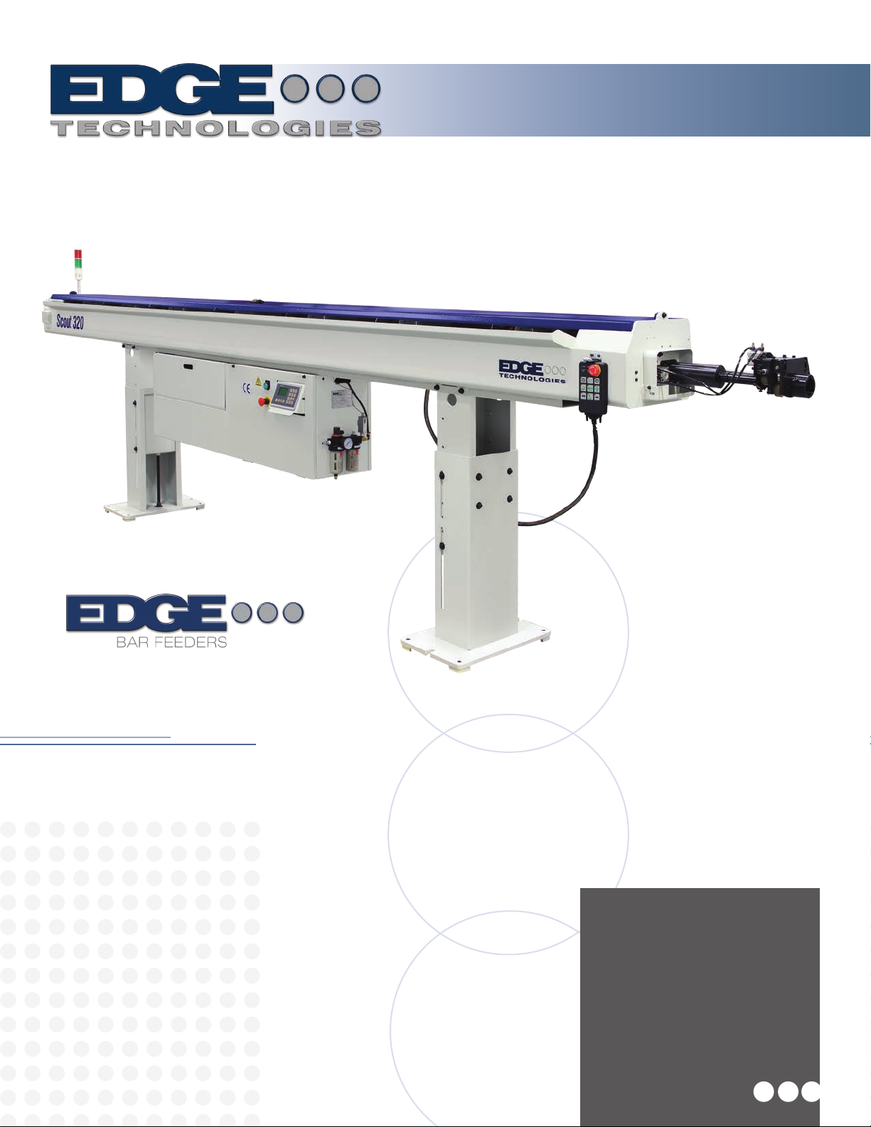
The Scout 320 is an
Automatic Magazine style
Bar Feeder designed for
feeding round, square and
hexagonal bar stock into
CNC lathes.
Scout 320
Scout 320
Version 3 Manual

i
Table of Contents
Section Page
1. General Information
1.1 Contents of this Manual ……………………………………………………… 1
1.2 Machine Safety ………………………………………………………………. 2
1.3 Indemnification………………………………………………………………… 2
1.4 Hardware and Software Changes…………………………………………… 2
1.5 Machine Data Plate…………………………………………………………… 3
1.6 Technical Support …………………………………………………………….. 3
2. Technical Information
2.1 Description of the Machine …………………………………….……….......... 4
2.2 Machine Footprint ………………………………………………….………….. 5
2.3 Specifications and Capacities ……………………………………….……….. 7
2.3.2 Compressed air supply including oil ………………………………………….8
2.4 Safety ……….....………………………………………………………….…..... 9
2.4.2 Covers …………………………………………………………………………...9
2.4.3 Lathe Door Safety …………………………………………………….…..........9
2.5 Emergency Stop Buttons………………………..…………………………......9
2.6 Electrical Safety…………………………………………………..…..…………11
2.6.2 Electrical Connection…………………………………………….………..……12
3. Transportation and Handling
3.1 Unpacking the Bar Feeder ….……………………………………….………...13
3.2 Transportation and Hoisting ………………………………………….………..14
4. Installation
4.1 Lathe Preparation …………………………………….……………….………..15
4.2 Typical Installation Guide ………………………………………………...……16
4.3 Height Adjustment ……………………………………………..……….………18
4.4 Distance from Lathe ….……………………………………….………….…….19
4.5 String Alignment…………………………………………………………….......20
4.6 Laser Alignment………. ……………………….………………………….……22
4.7 Installation Accessories...……………………………………...…………….…23
4.8 Anchoring…..………………………………………………………………….…26
4.9 Spindle Liner...…………….…….……...………………………………….……27

ii
5. Systems and Adjustments
5.1 Bar Feeder Component Locations…..………………….……………………. 28
5.2 Magazine Adjustment …….………………………………………….............. 29
5.3 Anti-Vibration Device/MAVD Adjustment …................…………………...... 30
5.3.2 AVD/MAVD Block Sets ……………………………………………………….. 33
5.4 Pusher Drive Belt ………….……………………………………………………34
5.5 Channel Set Components ….……………………………………..………….. 35
5.6 Material Measurement sensor/Cutting sensor ………………………………40
5.7 Gripper Assembly ……………………………………………………………… 41
5.8 Material Standards and Requirements …………………………………….... 42
5.8.2 Procedure for checking bar ………………………………………………..…..43
5.8.3 Bar Stock Preparation ……………………………………………………….…44
6. Control Operation and Description HMI
6.1 HMI Operation Description ……………………………………….…………... 45
6.2 Handheld Pendant ………………………………………………..…………….47
6.3 Basic Movement Functions ……….………………………..……...................48
6.4 Loading and Unloading Bar Stock …………………………………..………..49
6.5 Tower Light………………………………………………………………...…….50
6.6 HMI Operator Functions …………………………………………………...…..51
6.6.2 Changing the Unit of Measure …………………...……………………….... 52
6.6.3 Parameter Flowchart …………………………………………………..……….52
Parameters
L02 Feed too long safety of chuck close.……...…………..……………………... 57
L03 Feed too short safety of chuck close ………………….………………….…..58
L04 Bar pusher move forward of chuck open…..…………….…………………...59
L05 Bar pusher backward safety of chuck open….…………..……………….….59
L06 Inching number setup ………………………………...…………………..……59
S01 Speed of chuck open…………………………………………..………………. 60
S02 Speed of chuck close…………………………………………..……..……….. 60
S03 Manual feed speed…………………………..…………………..…………….. 60
S04 First feeding speed.………………………………………………..……………61
S05 Chuck enter speed…………………………………………….…..…………… 61
S06 Remnant push out speed……………………………………...….……………61
S07 Bar pusher draw back speed…………………………….……….…..………..61
Q01 Torque of chuck open…………………………………………………..……....61
Q02 Torque of chuck close………………………………………………….….……61
Q03 Torque of manual……………...………………………………….………….... 63
Q04 First feeding torque….……………………………………….………………....63
Q05 Chuck entry torque…………………………………………….….…………….63
Q06 Remnant push out torque …………………………………………………….. 64
P01 Movable anti-vibration opening position …………………………………….. 64

iii
P02 Movable anti-vibration second closed position …………………………...…64
P03 First anti-vibration opening position …………………………………………..65
P04 First anti-vibration closing position …………………………………………... 65
P05 First anti-vibration second closed position ……………………………….…. 65
P06 2nd anti-vibration opening position …………………………………………… 66
P07 3rd anti-vibration opening position …………………………………………….66
P08 4th anti-vibration opening position ……………………………………………. 67
P09 5th anti-vibration opening position ……………………………………………. 67
P10 Chuck facing distance ………………………………………………………….68
P11 Bar end position ……………………………………………………………...…69
P12 Stop providing oil …………………………………………………………........ 70
P13 First stop position for small bar pusher ……………………………………....70
P14 First feed end position ………………………………………………………….70
P15 Remnant push out position …………………………………………………… 71
P16 Inching retract stroke ………………………………………………………..… 71
P17 Bar push retract stroke …………………………………………………………71
P18 Bar push return position ………………………………………………………. 72
P19 Chuck facing distance fine tuning ……………………………………………. 73
P20 Bar end position fine tuning ……………………………………………………73
P22 Movable Anti-vibration close length …………………………………………..73
T01 Chuck open over time ………………………………………………………….74
T02 Chuck close over time ………………………………………………………….74
T03 Thrust of chuck close delay ……………………………………………………74
T04 Retreat delay time …………………………………………………………..…. 75
T05 Inching signal on time …………………………………………………………. 75
T06 Inching signal off time …………………………………………………………. 75
T07 Start signal delay time ………………………………………………………….76
T08 Timer setting after chuck open to redule torque …………..………………...76
F01 Movable anti-vibration open or close follow chuck ………………………….77
F02 Facing distance mode ………………………………………………………….77
F03 Feeding mode of chuck open ………………………………………………....78
F04 Synchronization device ………………………………………………………...78
F05 Change barfeeder mode ……………………………………………………….78
F06 Lathe mode ……………………………………………………………………...79
F07 Feeding direction mode ………………………………………………………..79
F08 Change start signal to CNC …………………………………………………...79
F09 Change door safety signal from CNC ……………………………………….. 80
F10 End of bar change mode ……………………………………………………....80
F11 Select bar pusher work method ……………………………………………….81
F12 Select loading method ………………………………………………………....81
F14 Bar end mode …………………………………………………………………...81
Change system time screen ………………………………………………..…82
Language select screen ………………………………………………………. 82
Change logo for homepage screen …………………………………………..82
Bar feeder signal output command screen …………………………………. 83
Bar feeder signal output command screen …………………………………. 83

iv
Bar feeder software version screen ………………………………………..…83
Load original preset value screen …………………………………………….84
Change number for the lathe screen ………………………………………....84
Bar feeder type screen .............…………………………………………….... 85
Transmission ratio screen ……………………………………………………..85
7. Maintenance
7.1 Maintenance chart ……………………………………………………………...86
7.1.2 Inspecting the pusher collet and revolving tip ………………..……………...86
7.1.3 Inspecting the air regulator..….……………………………………………......87
7.1.4 Pneumatic System Lubrication ……………………………………………..…87
8. Troubleshooting
8.1 Troubleshooting Chart.…………………….……………….………………….89
8.2 HMI Alarm Massage……………………………….………………………….. 90
Alarm 01…………………………………………………….…….……………..90
Alarm 02 …….……...…………………………………….…………….……… 90
Alarm 03 …….….…………………………………………..………………….. 90
Alarm 04………………………………………………………………………... 90
Alarm 05 …..….………………..………………………………..……………...90
Alarm 06.……………………………………………….…………………….….90
Alarm 07…………………………………………………..……………….…… 90
Alarm 08…………………………………………………………………………91
Alarm 09 …………………………….…………………….………………...…. 91
Alarm 10 ….………………………………….…………….………….……….. 92
Alarm 11 …………..………………………………………………….…………92
Alarm 12 …………………………................................................................92
Alarm 13 ……………..……………………………..……………………..…… 92
Alarm 14 ………………….……………………………………………………..92
Alarm 15 …………………….………………………………………...……….. 92
Alarm 16 ………………….……………………………………………………. 92
Alarm 17 ………………………………………………………………………...92
Alarm 18 ………………………………………………………………………...93
Alarm 19 ………………………………………………………………………. 93
Alarm 21 ………………………………………………………………………. 93
Alarm 22 ………………………………………………………………………. 93
Alarm 23 ……………………………………………………………………… 93
Alarm 24 ……………………………………………………………………… 93
Alarm 25 ……………………………………………………………………… 93
Alarm 26 ……………………………………………………………………… 93
Alarm 27 ……………………………………………………………………… 94
Alarm 28 ……………………………………………………………………… 94
Alarm 29 ………………………………………………………………………. 94
Alarm 30 ………………………………………………………………………. 95

v
Alarm 31 ………………………………………………………………………. 95
Alarm 32 ………………………………………………………………………. 95
Alarm 33 ………………………………………………………………………. 95
Alarm 34 ………………………………………………………………………. 95
Alarm 35 ………………………………………………………………………. 95
Alarm 36 ……………………………………………………………………..... 95
List of Servo Driver Alarms …………………………………………………. 97
9. Electrical Parts and Schematics
Electrical Parts …………….………………………………………..…………
10. Replacement Parts
Replacement Parts ……………………………………………………………

1
Scout 320 REV 3:2018
1. General information
Please read and understand the Manual before operating the bar loader
1.1 Contents of this Manual
The bar feeder/Unloader manufacturer has provided this manual as an integral part of the
machine. Adherence to the instructions of the manual will help prevent injury to the operator and
damage to the machine as well as helping to realize the maximum potential of the bar
feeder/unloader and machine tool. Particularly important points of information are preceded by
the following symbols and text:
Warning Indicates a potential danger to life or risk of personal injury. Exercise extreme
caution.
Caution Indicates a possible hazardous condition. Take precautions according to the
Instructions following these warnings to help prevent injury to personnel or damage to the
equipment.

2
Scout 320 REV 3:2018
1.2 Machine Safety
It is the user’s responsibility to provide proper safety devices and equipment to safeguard the
operator from harm for any particular use, operation or set-up, and to adequately safeguard the
machine, or machines, to conform to all Federal, State and Local Government Safety Standards
and all industry safety standards. It is suggested that only trained personnel operate the
machine and equipment because improper use could damage the machine and cause personal
injuries.
1.3 Indemnification
User agrees to indemnify and hold harmless Edge Technologies from any and all claims or
liabilities from accidents involving these machines caused by failure of users, his employees, or
agents to follow instructions, warnings or recommendations furnished by Edge Technologies, or
by failure of user to comply with Federal, State and local laws applicable to such equipment
including the occupational Safety and Health Act of 1970.
1.4 Hardware and Software Changes
As Edge Technologies continues to be the premier bar feeder supplier in the industry, ongoing
development and changes to software and hardware is normal.All software noted in this
manual are current at the print of this manual. For latest developments and changes please
visit www.EdgeTechnologies.com for the latest information or contact us.
3
Scout 320 REV 3:2018
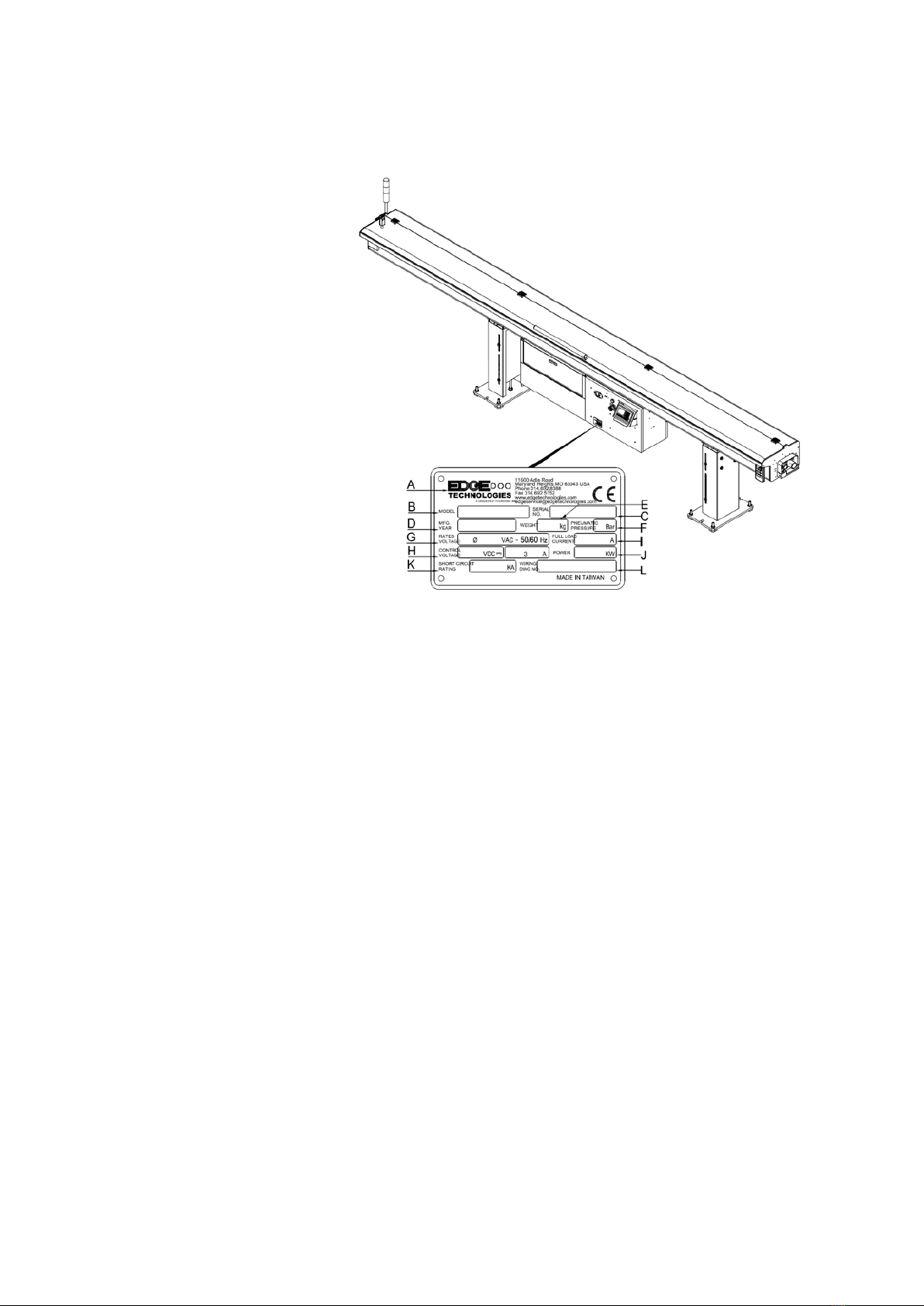
1.5 Machine Data Plate
A. Name of Manufacturer
B. Model (Type)
C. Serial Number
D. Manufacture Date
E. Weight of Machine
F. Pneumatic Pressure
G. Rated Voltage
H. Control Voltage
I. Full Load Current
J. Power
K. Short Circuit Rating
L. Wiring Drawing Number
For technical support please contact the Edge Technologies Service Department by phone at 314-
810-3927 or by email edgeservice@edgetechnologies.com
Important information
When inquiring about or ordering parts please have the machine
model type and serial number on hand. Refer to the machine data plate for this information.
1.6 Technical Support

4
Scout 320 REV 3:2018
2. Technical Information
2.1 Description of the Machine
The Scout 320 is an Automatic Hydrodynamic Magazine style Bar Feeder designed for feeding
round, square and hexagonal bar stock in lengths up to 12', in a diameter range of 3-27 mm, into
CNC lathes.
The Scout 320 comes equipped with a Mitsubishi controller and Servo drive standard. It also
features dual anti-vibration devices that stabilize the bar stock at two critical points between the
guide channel and lathe spindle maximizing RPM potential. The polyurethane guide channels
increase strength and stability.
Following Features
•Bar diameter capacity: 3 mm to 27 mm (.118” to 1.062”)
•Automatic loading magazine — 8 linear inches of rack capacity
•Double pusher, space saving design
•Polyurethane Quick Change guide channel — noise & vibration dampening
•Hydrodynamic support via high volume oil flow into channels
•Mitsubishi motion control — dependable and user friendly, allows easy bar feeder
parameter changes-belt drive unit
•Dual anti-vibration devices—one internal to the bar feeder, the other mounted between
the telescopic nose and the lathe headstock
Standard Features
•(1) Guide channel set to be chosen by customer. Several sizes to choose from, each
handling a specific stock range. See chart below (spindle liner required if channel set is
not lathe’s max capacity)
•(1) Standard telescoping front nose matched to the guide channel set
•(1) O.D. bar stock collet (to be chosen by customer, specific collet needed for each stock
diameter)
•Swiss headstock synchronization device
•Automatic remnant retraction, self-centering gripper
•Custom lathe cable and interface plugs
5
Scout 320 REV 3:2018
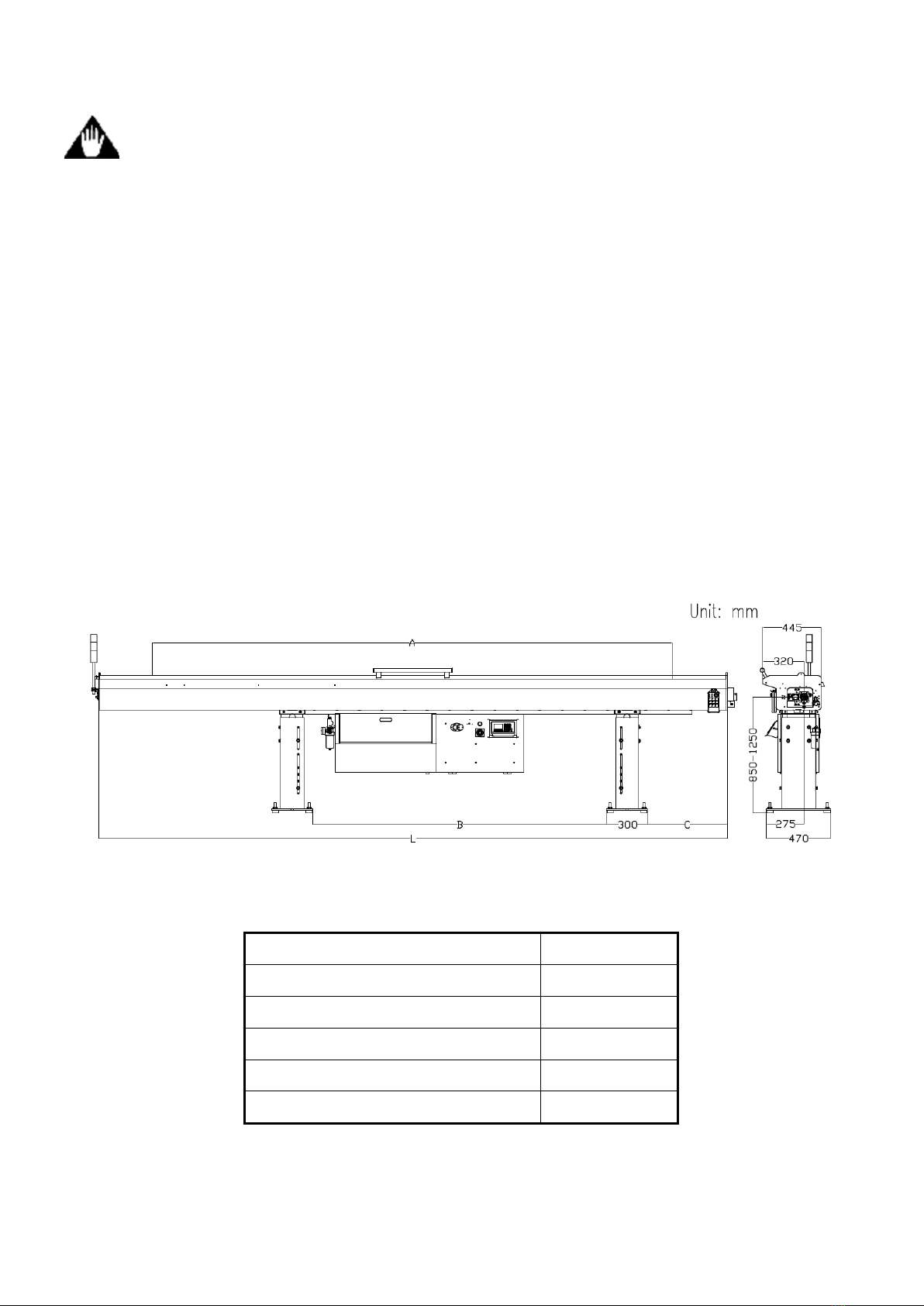
2.2 Machine footprint
Caution machine placement is important and proper planning should
be observed. A level floor free from cracks is ideal for anchoring of the
machine. As the customer is the one that decides on machine installation it
is their responsibility to be aware of proper floor requirements.
Placement of the bar feeder is important to gain the use of all the features. It is important to
review the lathe layout to be sure proper clearance exists of the assembly. On some lathes
accessories may prohibit proper placement such as tool changers and transformers. On certain
lathes a “Chucker Mode” option is available. Be sure to place the bar feeder close enough to
supply the reach for the pusher when the lathe is converted to “Chucker Mode” If placed too far
the remnant will be longer than normal. Be advised that too close may allow the bar feeder
telescoping nose to collapse into the head stock when the headstock moves to full negative over
travel.
Lengths Measurement
L 4599 mm
A (Max. Bar Length) 3800 mm
B 2150 mm
C 584 mm
Weight 420 kg
The image below references ideal spacing for operator movement.
Areas of interest
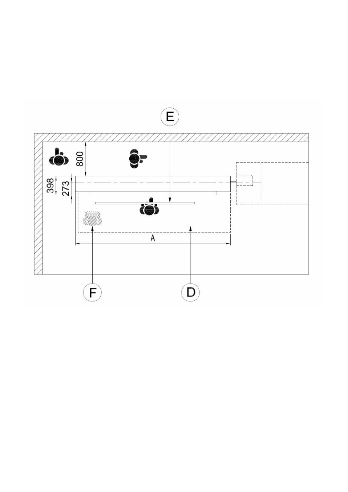
6
Scout 320 REV 3:2018
•D-operator area
•E-supply area
•F-remnant material area
The space must provide adequate working area.

7
Scout 320 REV 3:2018
2.3 Machine Specifications and Capacities
Oil Viscosity Brand Description
ISO 100
BP Energol CS 100
Castrol Magna 100
Chevron Circulating Oil 100
Elf Movixa 100
Esso Nuto 100
Mobil Vectra Oil Heavy
Shell Vitrea 100 / Tellus C 100

8
Scout 320 REV 3:2018
2.3.2 Compressed air supply including oil
Warning When working with compressed air proper PPE is required
in accordance with federal state and local laws.
Shop air must be present for machine installation
1. The supply hose for compressed air supply must be larger than 8mm
2. Pressure must be over 5~7kg / cm2, 71.11 – 99.56 PSI, Consumption about 50L/H。
3. Connect the air supply tube into (A). Pull up and rotate knob counter clockwise (B) and
set the pressure at 6kg / cm2, 71.11 – 99.56 PSI
Air system Lubricant Viscosity of 32, temperature 40℃, ISO VG type.
Oil level should be checked monthly. Be sure to use the recommended oil or damage to the
pneumatic system will result.
1. Adjust control air lubrication from cylinder, (C), 1-2 drops/1000 L air if necessary.
Air Unit Lubricating Oil – ISO VG32
BP Castrol Chevron Mobil Shell
Energol HLP 32 Hyspin VG32 Regal R&O 32 DTE 24 or Light Tellus 32
A: Air supply fitting
B: Air regulator knob
C: Oil supply knob
D: Lock ring

9
Scout 320 REV 3:2018
2.4 Safety
Warning safety switches should always be in place during bar
load operation.
The Scout is designed to be safe and reliable to operate. However, the machine can be
dangerous if used improperly by untrained personnel. Personnel should be familiar with the
operating instructions of the equipment before using and must follow standard safety practices.
The machine is equipped with safety devices to prevent accidental damage to the machine and
injury to the operator. These devices must not be bypassed or tampered with.
2.4.2 Covers
Warning covers should always be in place during bar load
operation. The Scout is supplied with covers to prevent access to moving
parts during operation. The hood of the machine is equipped with a safety
switch to place the machine in alarm if the hood is not closed. The magazine
cover prevents access to the material on the rack and the bar separators.
2.4.3 Lathe Door Safety
Warning lathe door safety if used should not be bypassed
An input to the Scout for monitoring the lathe door is available. If used, this input will prevent
movement of the machine when the lathe door is open. This parameter is normally set during
machine installation. It is not advisable that this feature is disabled once enabled.

10
Scout 320 REV 3:2018
2.5 Emergency Stop Buttons
Warning Indicates a potential danger to life or risk of personal
injury. Exercise extreme caution. These buttons should be tested monthly
to verify the proper emergency stoppage of the lathe and unloader.
There are two emergency stop buttons on the bar feeder. Button ES1 is the emergency stop
button on the HMI control panel housing. Button ES2 is the emergency stop button on the
remote pendant control. Pressing either emergency stop button disconnects the Emergency
Stop Relay.
Contacts from the emergency stop buttons are incorporated into the interface with the lathe
emergency stop circuit to enable the lathe to be manually placed into emergency stop
condition from the machine control panel.
The lathe emergency stop system will place the bar feeder into emergency stop as well.

11
Scout 320 REV 3:2018
2.6 Electrical Safety
WARNING!
ONLY QUALIFIED ELECTRICIAN OR SERVICEMAN SHOULD PERFORM ANY
ELECTRICAL TROUBLESHOOTING OR MAINTENANCE TO THIS
EQUIPMENT.
DO NOT PERFORM ANY MAINTENANCE, REPAIRS OR ADJUSTMENTS ON
THIS EQUIPMENT WITHOUT FIRST LOCKING OUT ALL ELECTRICAL
CONTROLS IN ACCOURDANCE WITH ALL FEDERAL, STATE AND LOCAL
SAFETY CODES.
PERSONNEL SHOULD BE TRAINED IN OSHA COMPLIANT LOCK-OUT/TAG-
OUT AND ELECTRICAL SAFETY PROCEDURES.
MAKE CERTAIN THAT THE POWER SUPPLY IS DISCONNECTED BEFORE
ATTEMPTING TO SERVICE OR REMOVE ANY COMPONENTS!
NEVER SHOULD ADJUSTMENTS, MAINTENANCE OR CLEANING BE
PREFORMED WITHOUT FOLLOWING PROPER SAFETY PROCEDURES IN
ACCORDANCE WITH LOCAL, STATE AND NATIONAL SAFETY CODES.
Before making any electrical connections be certain the voltage for which the bar feeder
requires from the lathe is verified with a voltmeter at the power supply connector. Verify this
voltage matches the required voltage of the bar feeder, see machine operator manual section
2.3 Specifications and Capacities. Failure to do so may result in injury or damage to the
equipment. Normally a bar feeder is ordered from Edge Technologies to be placed with a
specific lathe model. The wiring interface is set in accordance with current information received
to Edge Technologies. There are times the lathe manufacture may update and change the main
connector pin locations and circuits. It is important this is verified with the schematics of the
lathe and bar feeder. In some cases a harness is provided which must be wired into the lathe.
All previous safety advises and information must be adhered to. This form of connection allows
for quickly unplugged for cleaning or service without having to disconnect “hard wired”
connections.
Before starting the bar feeder, check to be sure no tools, packing, or other material have been
left in the machine or lathe.

12
Scout 320 REV 3:2018
2.6.2 Electrical Connection
Warning The power for the bar feeder and the input and output signals between
the bar feeder and lathe are supplied through the interface cable. The interface cable is normally
pre-wired for the lathe application when shipped from Edge. The installer should verify the
connection to the lathe before applying voltage to the system. If the lathe is not equipped with
an interface connection for the machine plug and cables will be supplied. This supplied harness
must be wired into the lathe electrical cabinet by a qualified technician. The lathe must support a
machine type interface for the machines to be connected.Additionally some lathes types power
output may be higher than the required 230 voltage. If this is the case an additional transformer
will be required to step down the lathe voltage for the bar feeder.
*Note the wiring interface contained in this manual is a generic 1 to 1 pin to wire call out.
Each lathe brand is different from one to another. Please contact Edge Technologies for
the proper interface schematic if you do not have one.

13
Scout 320 REV 3:2018
3. Transportation and Handling
Warning The weight of the machine without packaging is
approximately 1100 lbs. Only trained operators are to use lifting
equipment. Verify the equipment to be used for moving the machine is rated
to safely lift the weight of the bar feeder plus the packaging material. Make
special note that the machine is top heavy and take proper precautions.
3.1 Unpacking The Bar Feeder
Lifting and moving the bar feeder by forklift is the preferred method of handling the machine.
The machine should be moved only by personnel qualified in the operation of forklifts. The
forks must extend past the machine cabinet, see the drawings below. Lift the machine from the
side opposite the magazine maintaining sufficient clearance from the forklift mast to avoid
contact. Care should be taken to keep the load balanced. Do not lift the machine any higher
than necessary.
14
Scout 320 REV 3:2018
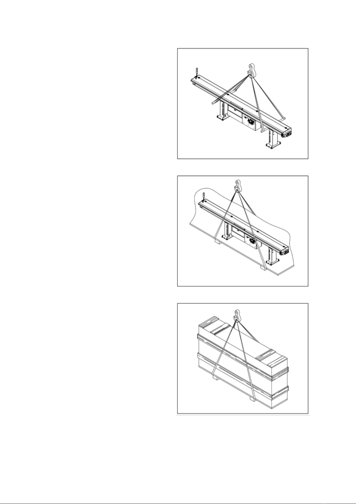
3.2 Transportation and Hoisting
Hoisting bar feeder
Place two steel bars (Diameter: 30mm,
length: 1M) under the bar feeder outside of
the stands, using suitable lifting straps hoist
the bar feeder.
Hoisting with bar feeder on pallet
Using suitable lifting straps positioned under
the pallet near the stands.
Hoisting the bar feeder in a crate
Using suitable lifting straps positioned under
the pallet near the stands.
Table of contents
Other Edge Industrial Equipment manuals


Popular Industrial Equipment manuals by other brands


FIELDQUIP
FIELDQUIP XGB Series Owner's/operator's manual

Dorner
Dorner 2100 Series Setup, operation & maintenance manual

TSCHAN
TSCHAN SD-5 Installation and Operation Manua

Siemens
Siemens 3VM9 0QA00 Series operating instructions

Louet
Louet Erica Assembly instruction

Pepperl+Fuchs
Pepperl+Fuchs IQT-F116-R4-V1 manual


