EdgeStar BIDW1802 User manual

EdgeStar, 8606 Wall St, Suite 1600, Austin, TX 78754
support.edgestar.com • [email protected] • edgestar.com
*Warranty service should be performed by an authorized service representative only.
Document Type: Service Manual
Version: V1.0 02042019
BIDW1802 Service Manual
18” Built-In Dishwasher
BIDW1802BL / BIDW1802SS / BIDW1802WH
CAUTION: Read all safety precautions in the manual
before servicing the unit

1
Table of Contents
SAFETY PRECAUTIONS..............................................................................................................................................2
General Safety ..........................................................................................................................................................2
Electrical Safety.........................................................................................................................................................3
Component Location View .............................................................................................................................................4
Front View.................................................................................................................................................................4
Top View ...................................................................................................................................................................4
Interior View ..............................................................................................................................................................5
Detergent / Rinse Aide Compartment View...............................................................................................................5
Interior View of Basin ................................................................................................................................................6
Left Side View ...........................................................................................................................................................6
Bottom View..............................................................................................................................................................7
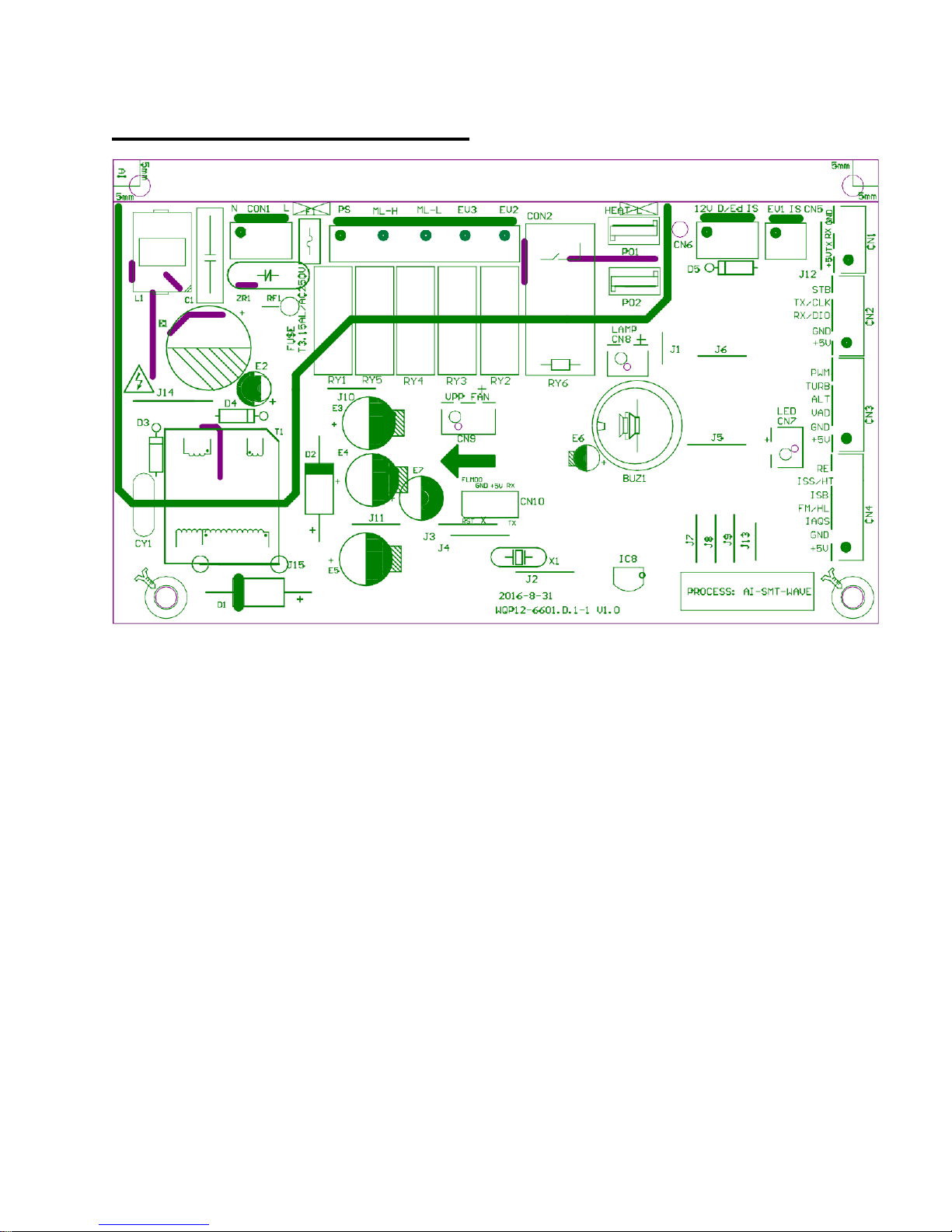
PCB Connection Locator View.......................................................................................................................................8
Dishwasher Components...............................................................................................................................................9
Outer Door.................................................................................................................................................................9
Control Panel.............................................................................................................................................................9
Door Switch Assembly ............................................................................................................................................11
Detergent / Rinse Aid Module..................................................................................................................................12
Inner Door Panel.....................................................................................................................................................14
Door Bottom Seal....................................................................................................................................................15
Tub Gasket and Trim...............................................................................................................................................15
Air Breaker Assembly..............................................................................................................................................16
Nozzle Duct.............................................................................................................................................................17
PCB.........................................................................................................................................................................17
Water Inlet Valve.....................................................................................................................................................18
Pressure Switch ......................................................................................................................................................19
Drain Pump Assembly.............................................................................................................................................21
Thermistor...............................................................................................................................................................21
Turbidity Sensor......................................................................................................................................................22
Heating Element......................................................................................................................................................23
Wash Pump Assembly............................................................................................................................................24
Sump Assembly ......................................................................................................................................................26
Sump.......................................................................................................................................................................27
Troubleshooting ...........................................................................................................................................................28
Factory Diagnostic Mode.........................................................................................................................................28
Error Codes.............................................................................................................................................................29
Exploded Views and Parts List.....................................................................................................................................30
Wiring Diagram ............................................................................................................................................................37

2
SAFETY PRECAUTIONS
WARNING: This manual and the information contained herein is intended for use
by certified technicians. The manufacturer or seller is not responsible for the
interpretation or misuse of the information provided, nor does it assume any
liability in connection with its use.
The safeguards and warnings indicated in this manual do not cover all possible
conditions which may occur. Common sense, caution, and care must be
exercised.
To prevent electric shock, always unplug an appliance from the power supply before attempting
any service.
Disconnect the power cord by grasping the plug, not the cord.
Do not bypass, cut, or remove the grounding plug.
Prevent water from spilling onto electric elements or the machine parts.
Always refer to the rating label on the appliance for rated current and voltage.
Always check line voltage and amperage.
Always use exact replacement parts.
Any attempt to repair a major appliance may result in personal injury and property damage.
General Safety
Always unplug an appliance from the power supply before attempting any service. Disconnect the
power cord by grasping the plug, not the cord.
Do not allow children or pets to play on or in the appliance.
This machine is not intended for use by persons (including children) with reduced physical,
sensory or mental capabilities, or lack of experience and knowledge, unless they have been given
supervision or instruction concerning use of the machine by a person responsible for their safety.
Do not install or store this appliance where it will be exposed to the weather.
Disconnect from the power socket before cleaning or maintenance.
If the plug (power cord) is damaged, it must be replaced by the manufacturer or an authorized
service representative.
This machine shall be repaired only by an authorized service representative. Only genuine
replacement parts should be used.
If connected to a circuit protected by fuses, use time-delay fuses with this appliance.
Do not lean items against the door.
Please do not close the door with excessive force. If it is found difficult to close the door, please
check for obstruction.
When you plan to dispose of this unit in the future, please comply with the local waste disposal
regulations. Remove any doors so that children and pets will not be trapped in the unit.

3
Electrical Safety
Do not exceed the power outlet ratings.
It is recommended that the unit be connected to its own circuit.
A standard electrical supply that is properly grounded in accordance with the National Electrical
Code and all state and local codes and ordinances is required.
Do not use outlets that can be turned off by a switch or pull chain.
Always turn the unit off and unplug it from the outlet when cleaning.
Unplug the unit if it is not going to be used for an extended period of time.
Do not operate the unit with a power plug missing the ground plug, a damaged cord, or a loose
socket.
Be sure the appliance is properly grounded.
Do not bypass, cut, or remove the grounding plug.
If the power cord is damaged, it must be replaced by the manufacturer or a qualified technician.
Do not use extension cords or power strips with this unit. You may need to contact an electrician
if it is necessary to use a longer cord or if you do not have a properly grounded outlet. Do not
modify the power cord’s length or share the outlet with other appliances.
Do not start or stop the unit by switching the electrical circuit’s power on and off.
Immediately unplug the unit if it makes strange sounds, emits an odor or smoke and contact
customer service.
Do not remove any part of the casing unless instructed by an authorized technician.
Before the appliance is removed from service or discarded, remove any doors and cut off the
power cord.

4
Component Location View
Front View
Top View

5
Interior View
Detergent / Rinse Aide Compartment View

6
Interior View of Basin
Left Side View

7
Bottom View
Note: Drain hose shown is shipping configuration

8
PCB Connection Locator View
CON1 L-N CN1 Not used
CON2 120V AC output CN2 Connecter to display board
Pin1=Drain pump CN3 Turbidity sensor
Pin2=High speed –Wash Pump CN4 Flow meter / leak detector
Pin3=Low speed –Wash Pump CN5 Water valve and door switch
Pin4=Not used CN6 Dispenser and door switch
Pin5=Not used CN7 Not used
PO1 PO2 Heater CN8 Not used
VPP Fan –Not used

9
Dishwasher Components
Outer Door
The outer door panel covers the inner door to the dishwasher and must he removed to
access the detergent/rinse module and bottom door seal.
To remove the outer door panel, first remove the 6 screws, and then separate the panel
from the inner door.
Control Panel
The control panel consists of the PCB user interface board. To remove the control
panel:
1. Disconnect the power supply to the dishwasher.
2. Remove the 8 screws.

10
3. Disconnect the signal line and remove the handle cover
4. Remove the 4 screws

11
5. Remove the PCB user interface board
Door Switch Assembly
The door switch assembly consists of the door lock and door latch. The door lock is
connected to the line (hot) side of 12 VAC.
WARNING: Power remains applied to the controller location at CN6, Pin 1. while the
door is open (unlatched).
To remove the door switch assembly:
Disconnect the power supply to the dishwasher.
Disconnect the 2 wiring harnesses from the door switch.

12
Remove the 2 screws
Detergent / Rinse Aid Module
The outer door must be removed to access the detergent / rinse aid module. (See Outer
Door.) The detergent/rinse module is connected by 4 wires and held in place by 10
snap joints. The detergent/rinse module operates on 12 VAC.

13
The detergent/rinse module automatically dispenses both the detergent and the rinse
aid at the appropriate times. The module is activated five times during a wash cycle.
Detergent is dispensed at the beginning of the main wash cycle for one time and rinse
aid at the beginning of the final rinse for four times. To remove and install the
detergent/rinse module:
1. Remove the 2 wiring harnesses
2. Use a flat-head screwdriver to release the snap joints and then pull in to remove
the module.
3. To install the new module press inward until it snaps into place.
4. Reconnect the 2 wiring harnesses

14
Inner Door Panel
To remove the inner door panel:
1. Disconnect power.
2. Remove the control panel. (See Control Panel.)
3. Remove the detergent/rinse module. (See Detergent / Rinse Aid Module.)
4. Remove the 2 screws from the hinge panel.
5. Remove the 2 screws from each of the base side panels.
6. Disconnect door spring and door cable.
7. Open the inner door approximately 10 degrees and lift the door until the door
hinge separates from the pin. A flat-head screwdriver may be used to assist.

15
Door Bottom Seal
The door bottom seal prevents water leakage by sealing the bottom of the door to the
tub. It cannot be replaced as a separate part on this dishwasher. It must be replaced as
part of the inner door panel. (See Inner Door Panel.)
Tub Gasket and Trim
The dishwasher tub seal prevents water leakage. The seal is fitted in a seal channel
that lines the rim of the dishwasher tub. To remove the tub seal or trim:
1. Open the dishwasher door.
2. Remove the dishwasher tub seal by grasping one end of the seal to peel it away
from the seal channel.
3. Remove the 2 screws and then pull the trim straight up off the lip of the tub.
4. Reverse the above the steps to reinstall.
Note: When installing the tub seal, make sure it is seated properly in the seal channel.
Run your finger over the seal to make sure it is smooth and even for a proper seal. A
correctly installed gasket will have both ends of the gasket equal distance from the
bottom of the tub.

16
Air Breaker Assembly
The air breaker assembly is mounted on the left side of the tub. Its purpose is to provide
a method of supplying water for the wash and rinse cycles. The air gap prevents the
dirty wash water from flowing back into the water supply system and prevents the water
pressure from dropping to less than atmospheric pressure. The air breaker assembly
also lets air into the tub to assist with drying. To remove the air breaker assembly:
1. Disconnect the power.
2. Remove the left side base panel.
3. Disconnect the wire harness from the air breaker assembly.
4. Open the door and rotate the air breaker nut and remove it from the air breaker
assembly.
5. Remove the 4 clamps from the pipes. Note: Do not reuse the clamps when
replacing the air breaker assembly. Replace them with new screw type hose
clamps.

17
Nozzle Duct
1. Disconnect the power
2. Open the door, remove the spray arm and the 2 screws on the lower spray panel.
3. Release the snap joints shown in the picture below then take out the nozzle duct
and lower spray panel.
PCB
The Printed Circuit Board is the center of the dishwasher. It receives and process the
signal from components, sends commands to components and deals with the feedback
information, etc. The PCB can be removed from the protecting box at the bottom of the
machine. To remove the PCB:
1. Disconnect the power.
2. Take out the cutlery basket, racks and filter system.
3. Lay the dishwasher on its back.
4. Remove the 2 screws from the kick plate and 2 screws from the insulating panel.
5. Remove the 1 screw on the PCB control box.

18
6. Remove the 2 snap fittings that attach the PCB to the control box.
7. Disconnect the wire connections and replace the PCB.
Water Inlet Valve
The water inlet valve is electronically controlled and solenoid-operated. The water valve
has an approximate resistance value of 1 KΩ. The water valve is mounted on a bracket
located on the left side of the front brace. To remove the water valve:
1. Disconnect the power.
2. Remove the 2 screws from the kick plate and the 2 screws from the insulating
panel.
3. Remove the 90° elbow for the water line.
4. Remove the side plate.

19
5. Carefully remove the 2 screws that hold the water valve to the front brace –do
not strip the screws.
6. Remove the plastic bracket for the valve like pictured below.
7. Disconnect the wire from the solenoid.
8. Remove the clamp and outlet hose from the valve.
Note: Do not reuse the clamp when replacing the air breaker assembly. Replace it
with a new screw type hose clamp.
Pressure Switch
The pressure switch is an overfill safety device mounted to the base and located at the
right rear. A clear plastic tube (the pressure switch hose) runs from the pressure switch,
around the air breaker assembly and to the sump. As the dishwasher basin fills with
water, the air pressure in the pressure switch hose increases. Normally, the electronic
control regulates the amount of time the water fill valve remains open. If the water fill
valve remains energized, the basin will overfill and increase the air pressure in the
pressure switch hose causing the pressure switch to open the circuit to the water valve
and energize the drain pump.
Table of contents
Other EdgeStar Dishwasher manuals

EdgeStar
EdgeStar BIDW18SS-1 User manual

EdgeStar
EdgeStar BIDW18001SS User manual

EdgeStar
EdgeStar DWP45E User manual

EdgeStar
EdgeStar BIDW1802SS User manual

EdgeStar
EdgeStar BIDW1802SS User manual

EdgeStar
EdgeStar Koldfront PDW60EB User manual

EdgeStar
EdgeStar DWP40W User manual

EdgeStar
EdgeStar DWP61ES User manual

EdgeStar
EdgeStar DWP40S User manual

EdgeStar
EdgeStar BIDW1801SS User manual