EdgeStar DWP62BL User manual

EdgeStar, 8606 Wall St, Suite 1600, Austin, TX 78754
support.edgestar.com • [email protected] • edgestar.com
*Warranty service should be performed by an authorized service representative only.
SERVICE MANUAL
EdgeStar Countertop Dishwasher
MODEL(s):
DWP62BL
DWP62SV
DWP62WH
Document Type: Service Manual
Version: V1.0 03222019
CAUTION: READ ALL SAFETY PRECAUTIONS IN
THIS MANUAL BEFORE SERVICING THE UNIT

1
CONTENTS
CONTENTS ..................................................................................................................................................1
SAFETY PRECAUTIONS.............................................................................................................................1
ELECTRICAL SAFETY.............................................................................................................................2
GENERAL SAFETY..................................................................................................................................3
SPECIFICATIONS........................................................................................................................................4
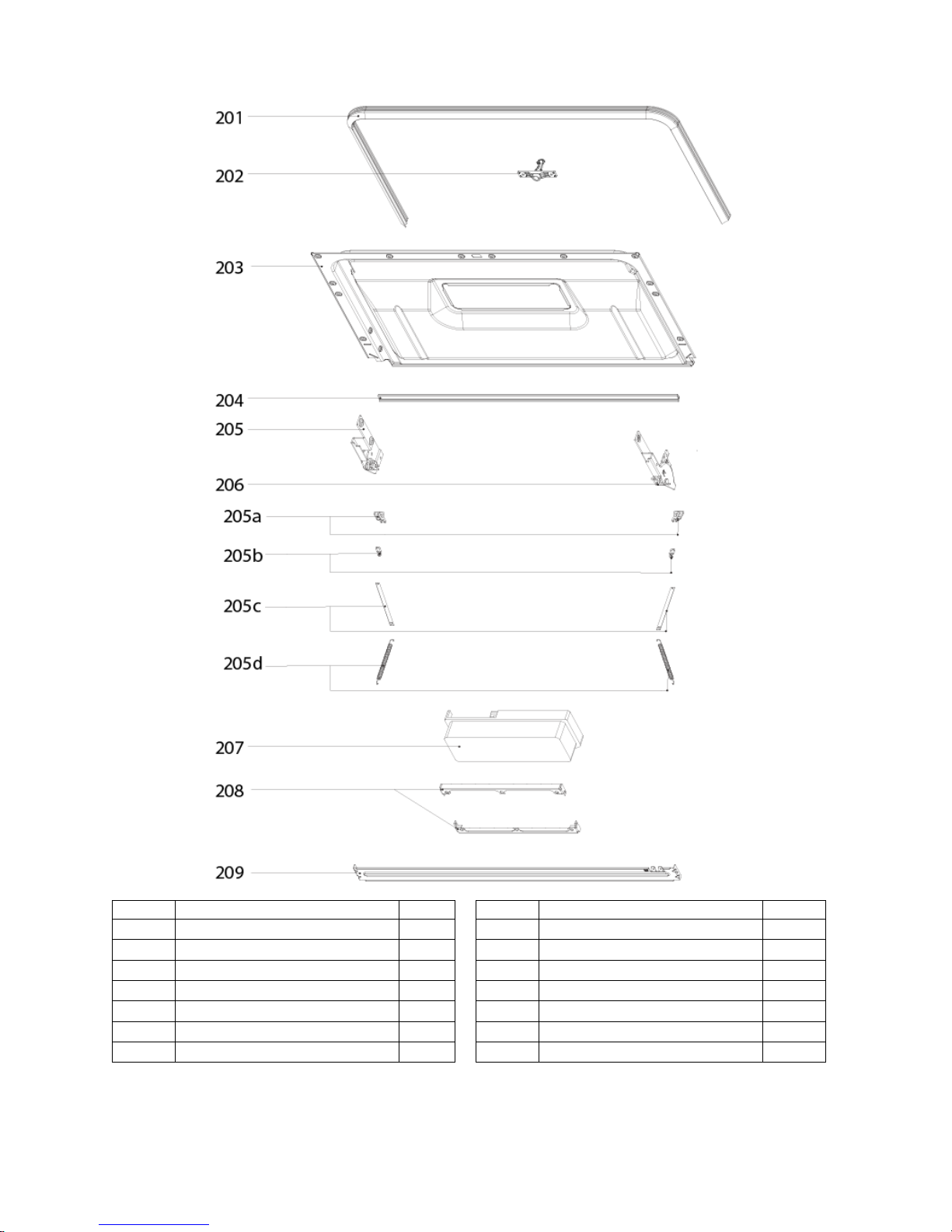
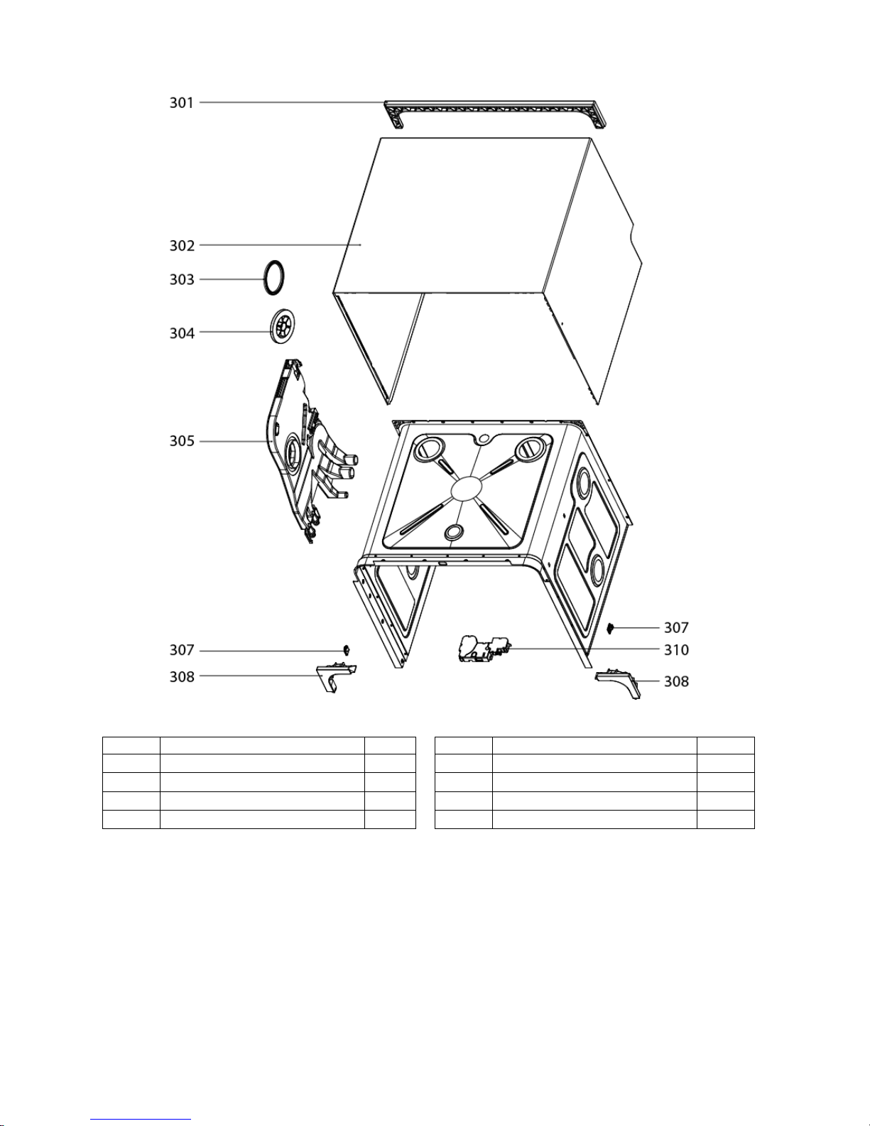
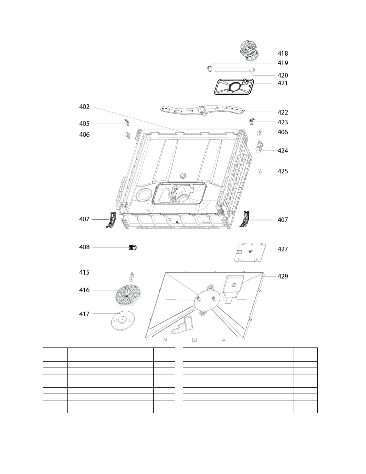
EXPLODED VIEWS AND PARTS LISTS.....................................................................................................5
WIRING DIAGRAM.....................................................................................................................................10
CONTROL PANEL......................................................................................................................................11
DETERGENT AND RINSE AID ..................................................................................................................12
DISASSEMBLY AND PARTS REPLACEMENT.........................................................................................13
DRAIN PUMP REMOVAL AND REPLACEMENT..................................................................................13
POWER CORD REMOVAL AND REPLACEMENT INSTRUCTIONS...................................................18
AIR BREAKER REMOVAL AND REPLACEMENT INSTRUCTIONS....................................................19
BASEBOARD REMOVAL AND REPLACEMENT..................................................................................24
CHECK VALVE REMOVAL AND REPLACEMENT...............................................................................26
FLOAT ASSEMBLY, FLOAT MICRO SWITCH AND FLOAT REMOVAL AND REPLACEMENT
INSTRUCTIONS.....................................................................................................................................33
HEATING ELEMENT REMOVAL AND REPLACEMENT......................................................................35
INLET VALVE REMOVAL AND REPLACEMENT..................................................................................40
DOOR COMPONENT REPLACEMENT REMOVAL AND REPLACEMENT.........................................42
DOOR GASKET REMOVAL AND REPLACEMENT INSTRUCTIONS..................................................49
DOOR SWITCH REMOVAL AND REPLACEMENT INSTRUCTIONS..................................................50
TROUBLESHOOTING................................................................................................................................53
SAFETY PRECAUTIONS
WARNING: This manual and the information contained herein is intended for use by certified
technicians. The manufacturer or seller is not responsible for the interpretation or misuse of the
information provided, nor does it assume any liability in connection with its use.
The safeguards and warnings indicated in this manual do not cover all possible conditions which
may occur. Common sense, caution, and care must be exercised.
To prevent electric shock, always unplug an appliance from the power supply before attempting
any service.
Disconnect the power cord by grasping the plug, not the cord.
Do not bypass, cut, or remove the grounding plug.
Prevent water from spilling onto electric elements or the machine parts.
Always refer to the rating label on the appliance for rated current and voltage.
Always check line voltage and amperage.
Always use exact replacement parts.
Any attempt to repair a major appliance may result in personal injury and property damage.

2
Electrical Safety
Do not exceed the power outlet ratings.
It is recommended that the unit be connected to its own circuit.
A standard electrical supply (120V, 60Hz), that is properly grounded in accordance with the National
Electrical Code and all state and local codes and ordinances is required.
Do not use outlets that can be turned off by a switch or pull chain.
Always turn the unit off and unplug it from the outlet when cleaning.
Unplug the unit if it is not going to be used for an extended period of time.
Do not operate the unit with a power plug missing the ground plug, a damaged cord, or a loose socket.
Be sure the appliance is properly grounded.
Do not bypass, cut, or remove the grounding plug.
If the power cord is damaged, it must be replaced by the manufacturer or a qualified technician.
Do not use extension cords or power strips with this unit. You may need to contact an electrician if it is
necessary to use a longer cord or if you do not have a properly grounded outlet. Do not modify the
power cord’s length or share the outlet with other appliances.
Do not start or stop the unit by switching the electrical circuit’s power on and off.
Immediately unplug the unit if it makes strange sounds, emits an odor or smoke and contact customer
service.
Do not remove any part of the casing unless instructed by an authorized technician.
Before the appliance is removed from service or discarded, remove the door and cut off the power
cord.

3
General Safety
Always unplug an appliance from the power supply before attempting any service. Disconnect the
power cord by grasping the plug, not the cord.
Do not allow children or pets to play on or in the appliance.
This machine is not intended for use by persons (including children) with reduced physical, sensory or
mental capabilities, or lack of experience and knowledge, unless they have been given supervision or
instruction concerning use of the machine by a person responsible for their safety.
Do not install or store this appliance where it will be exposed to the weather.
Disconnect from the power socket before cleaning or maintenance.
If the plug (power cord) is damaged, it must be replaced by the manufacturer or an authorized service
representative.
This machine shall be repaired only by an authorized service representative. Only genuine
replacement parts should be used.
If connected to a circuit protected by fuses, use time-delay fuses with this appliance.
Please do not close the door with excessive force. If it is found difficult to close the door, please check
for obstruction.
When you plan to dispose of this unit in the future, please comply with the local waste disposal
regulations. Remove the door so that children and pets will not be trapped in the unit.

4
Specifications
Description of product
Dishwasher (Portable / Countertop)
Model
DWP62BL / DWP62WH / DWP62SV
Color
Black / White / Silver
Number of Place Settings
6
Maximum Diameter of place Settings
10.5"
Wash Cycles
7
Accessories
Quick Connect Adapter
Faucet Adapter
Drain Hose
Water Inlet Hose
Max Water Temperature
149ºF (65ºC).
Water consumption (Normal Wash)
2.85 gallons
Spray Arms
Plastic
Drain Pump
Yes
Interior
Stainless Steel (430 SS)
Voltage / Frequency
120V AC / 60Hz
Input Power
1160W
Current
5.7 A
Delay Start
1-24 Hour
Unit Dimensions
H x W x D
17-1/4” x 21-11/16” x 19-11/16”
Box Dimensions
H x W x D
20-1/16” x 21-7/8'' x 23-13/16''
Net Weight
44.1 lbs.
Operating Temperature
(Normal Wash)
125°F
Noise Level
52 dB
Water pressure
15-20 psi

5
Exploded Views and Parts Lists
**NOTE: Not all parts are stocked or considered serviceable / replaceable by manufacturer
NO.
Description
Qty
NO.
Description
Qty
101
Handle Cover
1
106c
Delay Decrease Button
1
102
Control Panel Cover
1
106d
Start Button
1
103
Power Button
1
107
Outer Door
1
104
Light Cover
1
108
Baseboard
1
105
Button Cover
1
109
Power and Display PCB
1
106a
Program Button
1
110
Unit Wiring
1
106b
Delay Increase Button
1

6
NO.
Description
Qty
NO.
Description
Qty
201
Upper Door Gasket
1
205-c
Friction Strip
2
202
Door Latch
1
205-d
Spring
2
203
Inner Door
1
206
Hinge Assembly(Right)
1
204
Lower Door Gasket
1
207
Soap Dispenser
1
205
Hinge Assembly(Left)
1
208
Dispenser Bracket
2
205-a
Guide Vane
2
209
Hinge Join Panel
1
205-b
Friction Bar Hanger
2

7
NO.
Description
Qty
NO.
Description
Qty
301
Upper Back Cover
1
305
Air Breaker Assembly
1
302
Outer Shell
1
307
Door Caps
2
303
Air Breaker Washer
1
308
Upper Corner Cover Plate
2
304
Air Breaker Nut
1
310
Door Switch
1

8
NO.
Description
Qty
NO.
Description
Qty
402
Base Plate
1
419
Outlet Hose Clamp
1
405
Left Base Plate Bracket
1
420
Outlet Hose
1
406
Door Spring Bracket
2
421
Lower Flat Filter
1
407
Friction Strip Guide
2
422
Spray Arm
1
408
Check Valve
1
423
Right Base Plate Bracket
1
415
Float Microswitch
1
424
Connector Bracket
1
416
Float Switch Holder
1
425
Crimp Connector
3
417
Float
1
427
Main PCB box
1
418
Upper Cylinder Filter
1
429
Base Tray Cover
1

9
NO.
Description
Qty
NO.
Description
Qty
501
Inlet Valve
1
520
Wash Pump Motor Case
1
502
Hose Clamp
3
521
Wash Pump Motor Sealing Gasket
1
503
Air Intake Inlet Hose
1
522
Wash Pump Motor Sealing Ring
1
504
Power Cord
1
523
Wash Pump Motor Impeller
1
505
Power Cord Clasp
1
524
Impeller Screw
1
506
Drain Pump
1
525
Dish Rack Assembly
1
508
Drain Hose
1
530
Water Connection Components
510
Hose Clamp
2
530a
Supply Hose
1
511
Inner Drain Pipe
1
530b
Drain Hose
1
512
Inner Drain Pipe Sealing Ring
1
530c
Faucet Adaptor
1
513
Transfer Pipe Clamps
3
531
Heating Elements
1
514
Pump Joint
1
532
Drain Pump Inlet Pipe
1
516
Pump Transfer Pipe
1
533
Inlet Pipe Clamp
1
517
Temperature Sensor
1
534
Drain Connector
1
518
Wash Pump Motor Brackets
2
535
Flatware Basket
1
519
Wash Pump Motor
1

10
Wiring Diagram

11
Control Panel
Power Button: Press to turn the dishwasher ON/OFF.
Rinse Aid Warning Light: Indicates when the rinse aid dispenser needs to be refilled.
Wash Cycle Complete Light: Indicates when the current wash cycle has ended.
Program Selector: Press to select your wash cycle. The wash cycles will display in sequence.
Delay Button Increase: Press to increase the time of the delay by one (1) hour increments up to 24
hours. This establishes how much time will elapse before the selected wash cycle will begin.
Display Screen: Shows the current dishwasher status (running or on delay) as well as the remaining run
or delay time.
Delay Button Decrease: Press to decrease the time of the delay by one (1) hour increments down to 0.
Start/Pause Button: Press to start or pause the dishwasher wash cycle.
Wash Cycles
The sequential order of the wash cycles is as follows.
1. Heavy
2. Normal
3. Light
4. Glass
5. Baby Care and Bottles
6. Speed
7. Rinse

12
Detergent and Rinse Aid
USE PROPER DETERGENT ONLY
Use only detergent specifically made for use in dishwashers. Keep your detergent fresh and dry. Do not
put powder detergent into the dispenser until you are ready to wash dishes.
The amount of detergent to use depends on whether your water is hard or soft. With hard water, you
need extra detergent to alleviate the deposits that are left by the excessive minerals. Less detergent is
needed for soft water.
To identify whether your water is hard or soft, contact your water department. A water softener is
recommended for water that contains twelve or more grains. Without it, lime can build up in the water
valve, which could stick while open and cause flooding. Too much detergent with soft water can cause a
permanent cloudiness of glassware, called etching.
For heavily soiled loads, use the HEAVY (P1) wash cycle, fill one or both of the interior cups, depending
on the hardness of your water, and also fill the open cup on the dispenser lid.
Use the information in the table below as a guideline to determine the amount of automatic dishwasher
detergent to place in the dispenser:
Number of Grains
Detergent Cup(s) to Fill
Less than 4
15 cup
4 to 8
25 cup
8 to 12
15 and 25 cups
Greater than 12
15, 25 cups and the open cup

13
Disassembly And Parts Replacement
Basic Precautions
Always turn off the electric power supply before servicing or replacing any electrical component.
If grounding wires, screws, straps, clips, nuts, or washers used to complete a path to ground are
removed for service, they must be returned to their original position and properly fastened.
Make sure the power cord is not damaged.
Drain Pump Removal and Replacement
The drain pump functions to drain wash water after each cycle has been completed.
Tools Needed:
- Phillips Screwdriver - Flat Tip Screwdriver - Needle Nose Pliers
Step 1: Remove Base Tray Cover
Turn the unit over to locate the Base Tray Cover
Tip: Take a photo of the original assembly configuration for reference when reinstalling the panel.
Remove the screw that is circled in the photo below and set aside.
IMPORTANT: EMPTY CONTENTS OF UNIT
AND DISCONNECT FROM POWER SOURCE
BEFORE ATTEMPTING ANY REPAIRS.

14
Use a flat head screwdriver to release the nine (9) latches that secure the panel to the unit. While
gripping the panel, lift upward as the latches are detached to more easily remove the panel.
When latches are all released, remove the Base Tray Cover gently and be careful not to pull the
overflow switch wiring.
TIP: Use a pair of needle nose pliers to grab and lift up on the panel while releasing the latches.
Locate the float switch on the Base Tray Cover and disconnect the electrical connector.

15
Step 2: Remove the Drain Pump
Locate the drain pump circled in the below image.
Detach the electrical connectors from the pump.

16
Press the grey snap latch FIRST and then turn the drain pump counter clockwise to remove.
Slide the pump out of the housing.
Step 3: Install the new drain pump
Slide the pump into the housing.
Turn the pump clockwise until the locking latch clicks and the pump is locked in place.
Reattach the electrical connectors (Note: The drain pump is an A/C powered pump –wiring
connections are interchangeable).

17
Step 4: Reinstall the Base Tray Cover
Locate the float switch on the Base Tray Cover and reattach the electrical connector.
Push the Base Tray Cover into place securely latching the nine (9) snap latches.
Reinstall the screw to secure the Base Tray Cover into place.

18
Power Cord Removal and Replacement Instructions
The air breaker functions to supply water for wash and rinse while preventing siphoning or back-flow of
wash water into the water supply. It also functions to supply air venting to aid in dish drying.
Tools and Parts Needed:
- Phillips Screwdriver - Flat Tip Screwdriver - Needle nose pliers
Step 1: Remove Base Tray Cover
Refer to instructions to remove panel found in the “Drain Pump Removal and Replacement”
section of this document
Step 2: Locate the Connector Bracket
Step 3:Remove Crimp Connectors and Disconnect Power Cord Wiring
Remove three (3) Crimp Connectors that are seated into the Connector Bracket.
o
Turn the pump clockwise until the locking latch clicks and the pump is locked in place.

19
Air Breaker Removal and Replacement Instructions
The air breaker functions to supply water for wash and rinse while preventing siphoning or back-flow of
wash water into the water supply. It also functions to supply air venting to aid in dish drying.
Tools and Parts Needed:
- Phillips Screwdriver - Flat Tip Screwdriver
- Needle nose pliers - Gear drive hose clamps (4)
Step 1: Remove Base Tray Cover
Refer to instructions to remove panel found in the “Drain Pump Removal and Replacement”
section of this document
Step 2: Remove the Outer Shell
Remove the eight (8) screws as indicated in the below image. Set screws aside.
Lift up on the outer shell and unlatch from the front of the unit. Set outer shell aside.
Other manuals for DWP62BL
1
This manual suits for next models
2
Table of contents
Other EdgeStar Dishwasher manuals

EdgeStar
EdgeStar BIDW18001SS User manual

EdgeStar
EdgeStar DWP63BL User manual

EdgeStar
EdgeStar DWP40W User manual

EdgeStar
EdgeStar BIDW1801SS User manual

EdgeStar
EdgeStar BIDW18SS-1 User manual

EdgeStar
EdgeStar BIDW1802SS User manual

EdgeStar
EdgeStar DWP61ES User manual

EdgeStar
EdgeStar DWP40W User manual

EdgeStar
EdgeStar BIDW1802SS User manual

EdgeStar
EdgeStar DWP45E User manual