EDS RK 100 R User manual

EDS-TECHNICALINSTRUCTIONS
1
REFLECTIVE TYPE
OPTICAL BEAM LINEAR
SMOKE DETECTOR
RK 100 R
RK 100 RS
TECHNICAL MANUAL
TECHNICAL INSTRUCTIONS FOR
INSTALLATION,SETUPAND
MAINTENANCE
EDS-V.Ca' NovaZampieri6- 37057S.G. Lupatoto-VERONA-Tel.+39045547529 -Fax. +390458750065 -E.Mail:[email protected] -Web: www.eds.eu

EDS-TECHNICALINSTRUCTIONS
2
CHAPTERINDEX
1 - Qualified Personell
2 - Relevant Standards
3 - Installation
4 - Cable Connections
5 - Electrical Connections and Initial Setup
6 - Operation
7 - Optical Alignment
8 - Setup of Obscuration circuit
9 - Setup of Turbulence (heat) circuit
10 - Detector’s activation
11 - Autocompensation
12 - Operational Test
13 - Fault Output
14 - Alarm Memory
15 - Frontal Leds Operation
16 - Maintenance
17 - Sensitivity selection
18 - Technical data
QUICKINSTALLATION
The procedure below is intended for trained personell with previous
experienceininstallingEDSBeamSmokeDetectorsRK100R.
If you don’t have the needed experience please refer to the standard
installation procedure of this manual.
1 - fix the RK100R detector and FX reflector
2 - connect the cables
3 - set JP2-JP3-JP4-JP5-JP7 detector’s jumpers (see pag.10)
4 - make the optical allignment with the lamp
5 - set SW3 selector on the device according to the distance
between Detector and FX (see table in fig.7)
6 - place jumper JP1 in “ON” position (Alignment) and
power up the device
7 - optimize the device signal using:
• the P1 trimmer
• the adjustment screws V1-V2-V3 on the optical block
• a multimeter (or the STS01 instrument)
• blue/Red Led signal level indication (fig.8 board)
8 - regulate the signal between 4,7V and 5V with the P1
trimmer
9 - verify the functioning obcuring the FX
10 - select the desired sensitivity of the Obscuration circuit
with the SW2 selector (40-50-60-70%)
11 - select the desired sensibility of the Turbulence (Heat)
circuit with the SW1 selector (if used)
12 - set JP1 in “OFF” position to activate the device
13 - close the cover within 5 minutes
14 - wait at least 5 minutes for the device to become
operational
15 - perform operational tests
DEFAULTFACTORYSETTINGS
(Read ahead)
•SW1 - position 1 (minimum threshold level)
•SW2 - position 1 (minimum threshold level )
•SW3 - position 4 (maximum Transmitter power )
•JP1 - position 2-3 (optical allignment on)
•JP2-JP3 - position 2-3 (contact NC)
•JP4 - position 1-2 (contact NC for Fault relay))
•JP5 - position 1-2 (memory off)
•JP7 - not inserted (alarm relays NC)
•P1 - level adjustment trimmer at half scale
NOTE - the version RK100RS is not equipped with the detection circuit of Turbulence. Therefore there are no items
related to this circuit. In the reading and in the use of technical instructions, keep in mind this indication.

EDS-TECHNICALINSTRUCTIONS
3
REFLECTIVETYPE
OPTICAL BEAM SMOKE
DETECTOR
RK100R - RK100RS
GENERAL
The RK100R detector is a newly-conceived microprocessor
optical beam smoke detector, that bases its working concept on
the interaction between the smoke present in a room and an infrared
beam emitted by a transmitter and reflected by an optical reflector
(fig.1).
The normal installation consists in mounting the detector on a wall
of the room to be protected and in fixing the FX reflector (FX01,
FX02, FX03, etc depending on the distance- see table in fig.7) on
the opposite wall.
For a correct installation, we recommend to read and follow our
instructions carefully. The excellent working results of the device
will widely compensate the time spent reading these instructions.
1 - QUALIFIED PERSONELL
1.1 - All the operations of installation, setup, startup, maintenance
and verifications of operation of the RK100R detector, must only
be performed by qualified personnell. These people are qualified
for their experience, specialization courses, knowledge of the
current standards and of the technical specifications, features
and usage method of the product. These people therefore are able
to avoid errors or damages and assure an optimal functioning of
the product.
1.2 - The RK100R detector must be used according to the tecnical
data and to the information of this manual, to the installation and to
the ambiental and operational condition
2-RELEVANTSTANDARDS
2.1 - For the installation in European Community countries you
must follow the EC standard EN54-14 (Fire detection and fire
alarm systems). In extraeuropean countries you must respect the
relevant international and national standards.
3- INSTALLATION
3.1 - For the installation of the RK100R detector we suggest to also
use, besides the normal tools (drill, expansion plugs, etc), the
followingelements:
•1-7mm“C”Key
•1-alignmentlamp(werecommendtouse LAL02 lamp (optional) or
an electric torch with powerful and contrated beam)
•1-multimeter(werecommendan analogichandTesteror an analogical
STS01 meter (optional) to be plugged on the special connector
positioned on detector’s circuit.
3.2 - Unscrew the 4 fixing screws (fig. 2) and remove the cover
3.3 - Install the detector at a distance from the ceiling within the
10% of the height of the room to protect. This distance can be
variedby the system designer if particularenvironmentalconditions
exist. Wall fixing must be done with care using the 4 holes provided
inside the container. If the wall is a solid masonry one, 4 expansion
plugs are enough. It’s extremely important that the fixing wall or
surface is rigid and not subject to deformations.
3.4-Pass the cables through the holes obtained breakingthesuitable
zones marked on the sides of the detector’s base.
It is important to use a suitable chock with a connecting pipe to
avoid that the dust penetrates inside the device, possibly causing
failure to its correct functioning.
3.5 - Install the FX reflector on the opposite wall at the same
distance from the ceiling as the detector. It is not necessary that
the device is perfectly in front of the optical reflector or
perpendicular to it (small angle shift are possible in all directions).
4 - CABLE CONNECTIONS
4.1-The low current of the device (20 mAwithnormallyopen (NO)
alarmrelayand30 mAwithnormallyclosed(NC) alarmrelaycontact)
allows to use small size section cables. We suggest a shielded cable
with8 conductors + the shield ( 2x0,75 mmq forpowerconductors +
6x0,22 mmq for the signal conductors) for a distance up to 1 Km.
In such way it’s possible to take at distance:
•alarm signal (C1-N1 terminals)
•alarm signal for the tourbolece (C2-N2 terminals)
•fault (C3-N3 terminals)
•analog signal output (SIG terminal) - for level signal
measurement from distance
The cable shield must be connected as in fig.12

EDS-TECHNICALINSTRUCTIONS
4
5-ELECTRICALCONNECTIONSAND INITIALSETUP
5.1 - Connect the device cables as shown on fig. 11 and fig.12.
The used symbols indicate what follows:
• (V+) - (V -) - supply’s terminals 11 - 30 Vcc.
• (C1) - (N1) - normally closed alarm relay contact. The connection
is valid when the detector is not in alarm state and JP2 jumper is in
2 - 3 position. If JP2 is positioned on 1-2 the contact results
normally open. C1-N1 terminals are voltage free.
• (C2) - (N2) - turbulence alarm normally closed contact relay.
Connection is valid when the detector is not in an alarm state and
JP3jumperisin2-3position..If JP3ispositionedon1-2thecontact
results normally open. C2-N2 terminals are voltage free.
• (C3) - (N3) - normally closed fault relay contact. Fault relay is
normally powered (intrinsic safety). Connection is valid when the
detector is not in fault state and JP4 jumper is in 1 - 2 position. If
JP4 is in 2-3 position the contact is normally open. C3-N3
terminals are voltage free.
•(SIG)-0-5Vanalog output terminal.To use only during allignment.
5.2 - JP SETTINGS :
JP1- To enter/exit the optical alignment procedure. To activate
the procedure of optical alignment JP1 must be in 2-3 (ON)
position. To deactivate the procedure of optical alignment JP1 must
be in 1-2 (OFF) position.
• JP1 position 2-3 (ON).........alignment procedure ON
• JP1 posizion 1-2 (OFF).......alignment procedure OFF
JP2 - JP3 - JP4 - To set the output contacts respectively of Alarm
relay, Turbulence relay and Fault relay to normally closed NC or
normallyopen NO (cap. 5.1)
TheRK100Rdetectorisnormallyfactory preset with normallyclosed
NC contacts. For the alarm relay the indication of JP2 is valid if JP7
is in OFF position.
JP5 - Activate the alarm memory function or to deactivate that
function (detector automatically resets alarm output)
• position 1-2 alarm memory OFF. When the detector gets out of
alarm condition it automatically resets the alarm output
• position 2-3 alarm memory ON. In case of alarm the detector’s
alarm output persists until power supply is switched off for at least
5 seconds
JP6 - Microprocessor reset (SW reset)
JP7 - Selection of alarm relay operational mode : normally
powered (NC) or not powered (NO)
• JP7 ON - relay of alarm normally powered (in case
of alarm the relay gets not powered). In this case the indication of
the JP2 is inverted
• JP7 OFF - relay of alarm normally not powered (in case of alarm
therelaygetspowered).InthiscasetheindicationofJP2isaccording
to figures 11-12 (diagrams of the terminal block and the classical
scheme of connection to a control system to terminated lines)
6 - OPERATION
6.1 - The RK100R detector is equipped with 2 circuits of detection
of the smoke produced by a fire:
• Obscuring - circuit sensitive to the obscuring.
This circuit founds its operation on the diminution of the infrared
ray intensity, along the optic run between the detector and the
reflector, caused by the smoke
• Turbulence - circuit sensitive to the Turbulence.
During the beginning phase of the fire, generally there are some
clouds of smoke and warm air that climb toward the ceiling. When
these clouds and warm air intercept the infrared ray produced by
the detector, they provoke a perturbation of it because produce a
variation of optic-physics characteristics in the transmission of the
infrared ray. This variation is obviously time correlated.An oppor-
tune circuit has been projected to reveal this variation and, when
these reach the ampleness and the duration in the time programmed,
a signal of alarm is produced. The sensibility and the delay of
intervention of this circuit are independently adjustable so that to
fullysatisfytheapplicationsofthetechnician.Theadvantageoffered
by this circuit is a great speed of fire detection, because it is detected
in dynamic way in its initial phase.
7 - OPTICAL ALIGNMENT
7.1 - Proceed with the optical alignment of the detector and FX
reflector. To facilitate the operation we suggest to do it in low
ambient light conditions and to proceed in the following way:
• place in front of the reflector FX (fig.3) an optical alignment lamp
able to project a concentrated and sufficiently intense light beam.
(werecommendtheEDSalignmentlampLAL02)
• direct the light beam of the lamp to the lenses of the detector
• look at the screen that is behind the lens, inside the Transmitter
(right lens). On it you will see a bright point that represents the
image of the lamp
• move the optical block using her special screws V1-V2-V3 with a
key, so that the bright point falls in the center where a small hole is
presentthroughwhichthephotodiodeisvisible(fig.4).It’simportant
that the bright point falls on the photoemitting zone of the
photodiode. This zone is represented by the small dark dot in the
center of the photodiode (fig.4). In such way the detector will be
alligned with the reflector FX.
After doing the optical alignment of the detector it is necessary to
dotheelectricsignalsettingoperations,procedingwiththefollowing
instructions.
8- SETTINGOFTHE OBSCURATIONCIRCUIT
Setting Operations of the electric signal must be perform
according to the following sequence:
8.1 - Do not power supply the detector
8.2 - Rotate the SW3 selector in one of the positions 1-2-3-4
(fig.9) according to the distance between the detector and the
reflector (FX01-FX02-FX03, etc.) (reference fig.7)
8.3 - Move the jumper of Initial Set JP1 (fig.9) in the position ON
(Alignment) to activate the phase of initial setting
8.4 - Power up the detector
8.5 - The blue led and the red one will start to work in the way
described ahead in cap. 8.12. Before going on to this chapter read

EDS-TECHNICALINSTRUCTIONS
5
what’s following
8.6 - the P1 trimmer (regulation of the signal level) is regulated in
factory to the 50-60% and it corresponds to a signal of 5V to the
maximum distance
8.7 - To get the best results in the following operations, we
recommend the use a measuring instrument (Multimeter),
preferably an analog hand type, for better control of the variations
of the signal during the setup. Good results are also obtained using
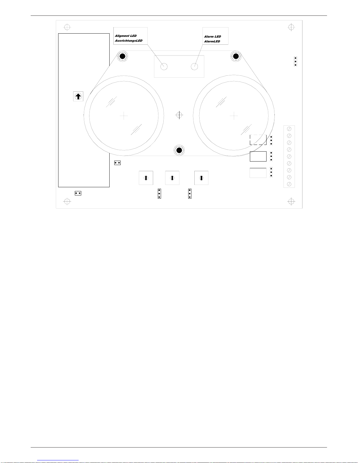
analog meter STS01 (optional), designed for this application, that
must be inserted on the special connector CN4, set on the printed
circuit of the detector (v. fig. 11). If you don’t have a Multimeter
or the STS01, you can perform the setup operations anyway
evaluating the signal level with the frontal Leds indications as
described in chap.8.12
8.8 - If available, connect a 5V fullscale multimeter between the
SIGterminaland the negative power supply one and read the analog
output signal. Instead of the multimeter, it is possible to use the
STS01 meter (optional - fig. 11). If the output signal is very low, it
means that the operations of optical alignment described in chapter
5, have not been performed in the right way and therefore must be
repeated
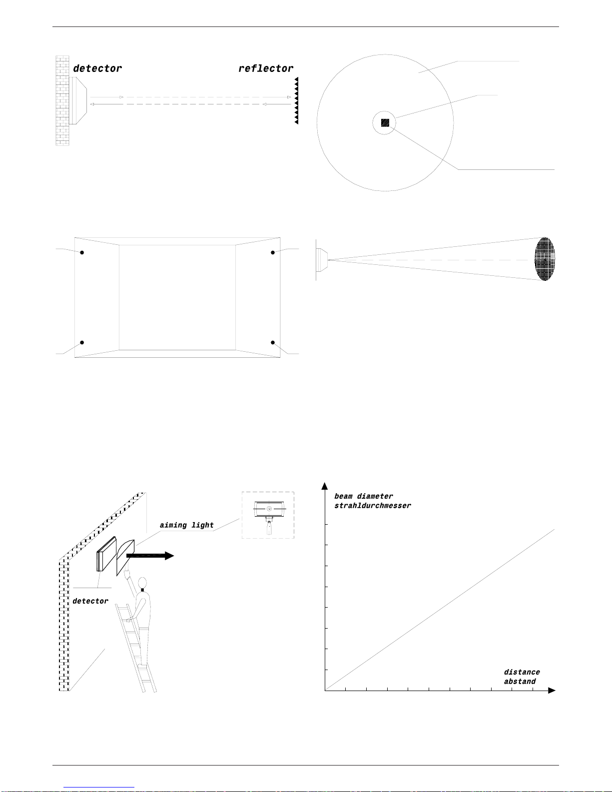
8.9 - The detector emits a conic beam which form and dimension,
in relation with the distance between detector and FX, are
explained in figures 5 -6.
It’s important that the FX is in the center of the detector’s conic
beambecause,undertheseconditions,even if some small movements
of the wall on which the transmitter is mounted on happen (caused
by deformations), the reflector remains always within the beam and
therefore active.
Toobtainthis,theoperations of fine centering with output signal
measuring,explainedbelow, mustbeperformedwithcare.
8.10- Regulate the signal to about 3V acting on the trimmer P1
(fig.9)
8.11 - Search for the maximum output signal optimizing the optical
alignment of the Transmitter acting slowly and in sequence on the
3 screws of regulation V1-V2-V3 set on the optic crew. This pro-
cedure take some time however, if well performed, it assures a
perfect work of the detector for many years. We advise to use the
following procedure:
• On the detector slowly turn the screw V1 clockwise and then
look at the value of the signal visualized on a multimeter. If the
signal increased (for example from 3V it rised to 3,5V) then again
turn the screw V1 of the detector clockwise and then look at the
value of the signal.
• Continue with this procedure as long as the signal increases.
When it has the tendency to decrease instead, stop the operation
on the screws V1 of the detector returning to the previous position.
• If during the operation the signal overcomes 4,5V, to avoid the
saturation, act on the trimmer P1 to bring the signal back to 3 V,
allowing the best evaluation of the variations of the signal.
• After finding out the maximum og the signal acting on the screw
V1, perform the same operations on the screws V2 and V3.
In such way the best possible position of optical allignment is
reached. This procedure is important because it will assure a perfect
operation of the detector for long time.
8.12 - If you don't have a multimeter, it is still possible to get good
results in the optical alignment of the detector, looking at the
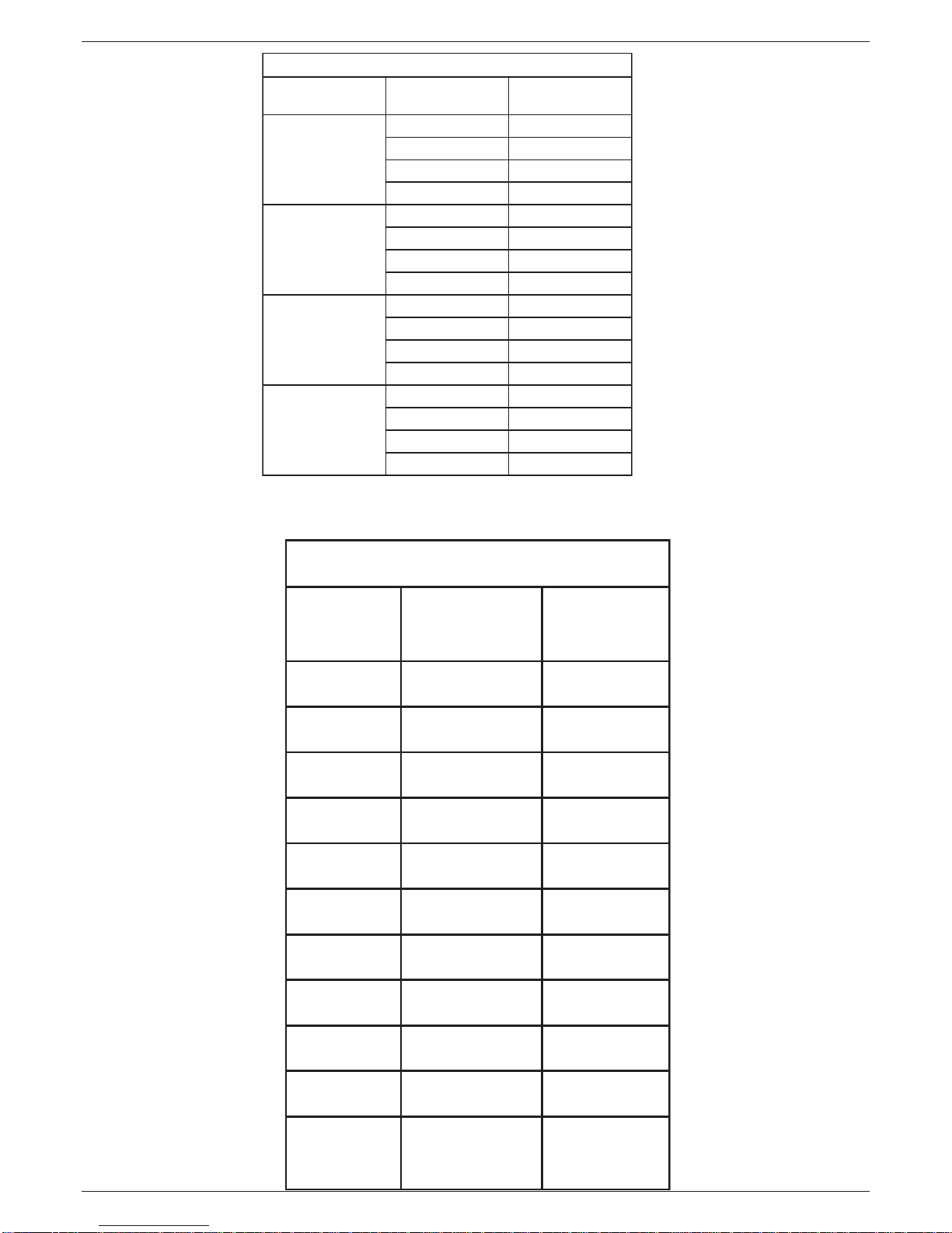
detector’s blue and red leds indications. Operation is the following:
• 1 flash of the blue Led: 1 Volt
• 1 flash of the red Led: 0.5 Volts
• if the signal is smaller of 0.5V the blue led and red one are off
• if the signal in the range 0.5-1 V the red led performs 1 flash,
remains off for 2 seconds and then it repeats the sequence
• if signal is among 1-1.5 V the blue led flashes once, remains
off for 2 seconds and then it repeats the sequence
• if signal is among 1.5-2V the blue led flashes once and the red
led flashes once. They remain off for 2 seconds and then the
sequence is repeated
• if signal is among 2-2.5 V the blue led flashes 2 times, remains
off for 2 seconds and then it repeats the sequence
• if signal is among 2.5-3V the blue led flashes 2 times and the
red led flashes once. They remain off for 2 seconds and then
the sequence is repeated
• same type of indication up to 4 V
• if the signal overcomes 4 V, the blue Led flashes faster and
faster as the frequency signal increases up to 4.7V
• when the signal overcomes the 4.7V and in the range 4.7V -
4.9V, the blue led is continously ON. This is the position of
optimal setup
• if the signal gets over 4.9V the two blue and red leds are
permanently on. This is the saturation indication.
The table of fig.8 recaps the leds operation.
8.13 - After doing the operations of fine optical alignment using
the Tester or the indications of the Leds, you must regulate the
signal slowly acting on the trimmer P1, between 4.7V and 4.9V.
When the signal it is included within this range, the blue Led is
costantly ON. This it is the position of optimal setup. If the signal
overcomes the 4.9V, the detector goes in saturation and the blue
and red leds are both ON. Therefore acting on P1, it is necessary
to set the signal between 4.7-4.9V so that the red Led switches
OFF and is only the blue Led remains ON (to avoid saturation).
Attention! - this regulation is not critical. The procedure
indicated above is the optimal one, but it is enough if the blue
Led is flashing or constantly ON to have a good setting.
However it is necessary to avoid the saturation (red Led ON).
The microprocessor automatically compensates the
inaccuracies of the setting.
8.14 - It must be checked out that, since the detector founds its
operation on the reflection of the projected beam, this reflection
is effected by the FX reflector only and not from other elements.
To be certain that the signal is produced by the reflection of its FX
reflector and not from other elements, it is useful to do a simple
verification. It is necessary to obscure the reflector with a non
reflecting screen (opaque). In that case the signal on SIG terminal
must decrease under 0,5V. (check indications in the following
pages).
8.15 - Select the alarm threshold level of the circuit sensible to
obscuration acting on the selector SW2 keeping in mind the
following :
• position 1 - low sensitivity - obscuration alarm threshold set to 70%
• position 2 - low to medium sensitivity - obscuration alarm threshold set
to 60%
• position 3 - medium to high sensitivity - obscuration alarm threshold
set to 50%
• position 4 - high sensitivity - obscuration alarm threshold set to 40%
8.16 - Sensitivity must be regulated according to the environmental

EDS-TECHNICALINSTRUCTIONS
6
situation. The setting must normally be a medium sensitivity level,
but in case of dusty and perturbed environments it will be useful to
set a lower sensitivity level.
9- SETTING OFTHETURBULENCE CIRCUIT
9.1 - The RK100R detector is equipped with a special additional
circuit for the detection of air Turbulence (heat). This circuit is
independent from the classic obscuration one and in particular
situations it can be used to increase the performance of the detector.
If these particular situations are not present the turbulence circuit
can be left unused.
9.2 - This circuit is particularly useful when, for environmental
reasons, the optical beam smoke detector must be installed at
distances from the ceiling higher than the nominal. When the fire
begins,itproducessmokeclouds and hot airbubblesthatgoup.When
these bubbles intercept the infrared beam they perturbate it because
they produce a change of the optical-physical characteristics of
infrared beam. These changes are obviusly correlated in time. This
circuit has been designed to detect these changes and, when these
changes reach the programmed amplitude and time lenght, an alarm
signal is generated. The advantage of this circuit is the quicker fire
detection,becausethefireis detected in its beginning phase.Atypical
example is the complete protection of the dome of a church with
important pictures on its surface. The linear optical beam smoke
detectors must be installed at the baseline of the dome and therefore
much lower than the ceiling. In this case using the turbulence (heat)
detection circuit is very useful to improve the detection.
9.3 - Selection of the sensitivity level of the circuit sensitive to
Turbulence(heat).
The operation is performed acting on selector SW1 of the detector
that has 4 positions (fig.9).
• sensitivity increases from 1 to 4
• position 1 : minimum sensitivity
• position 4 : maximum sensitivity
The regulation must be performed with caution, because with an
higher sensitivity a quicker response time is obtained, but also the
probability of false alarm is increased. So the sensitivity selection
must be done according to the environmental conditions. If these
conditions are good, an high sensitivity regulation is possible. If
in the environment, because of the normal working conditions,
dust's clouds, vapor or smoke are systematically produced, it will
be necessary to adjust the sensitivity to a lower level, so that these
factors doesn't generate false alarms.
10-DETECTOR’SACTIVATION
10.1 - Put the jumper of Initial Set JP1 in position 1-2 (OFF)
10.2 - The blue led ofAlignment flashes in particular way (2 flash
slow flashes - 1 break - 2 fast flashes, repeated)
10.3 - Install the cover. The operation of detector’s closing must
be done within 5 minutes. The level of the signal will be decreased
because of the absorption caused by the cover
10.4 - The inside electronics attends 5 minutes for the installation
of the cover and later performs a rapids procedure (time 1-2
minutes) take again the signal of the RK100R to 4,7-5V
10.5 - Stopped this phase of adjustment, the detector becomes
operational. The blue Led ofAlignment stops (detail cap.10.2) and
and it begins to flash as described in 10.6
10.6 - every 10 seconds the blue Led will emit a short flash that
points out the normal operations of the detector. In case of alarm
the frontal red LED turned fixed ON and remains turned ON until
it stops the state of alarm or, if it is setted the function of memory,
until the supply is not removed for 5 seconds (v. cap.14)
11-AUTOCOMPENSATION
11.1 - The inside electronics of the detector is endowed with a
special circuit of auto-compensation of the signal. If the detector
is installed inside a particularly dusty place, the dust that is
deposited on the front surface of the cover causes a drop of the
signal. This drawback is automatically eliminated by the circuit of
autocompensation.
12 - VERIFICATION OFOPERATION
12.1 - Verification of the sensitive circuit to the obscuring.
The verification is carry out simply by darkening with an opaque
screen the reflector. After 10 seconds, detector alarm relay must
activate / not activate(cap.5.2 - jumper JP8) and the frontal red
Led of alarm must be turned ON. After, remove the screen, the
relay of alarm must be restored and the red Led restarts to flash
every 10 seconds. If the function of memorization is activated
(cap.14) for the restoration, it is necessary to remove the eletric
power from the detector for 5 seconds.
Attention!
• This test must be effected darkening the reflector only
• The screen must not be set in front of the detector
12.2 - verification of the sensitive circuit to the turbulence.
Verify of the sensitive circuit to the turbulence putting a non-
reflecting screen in front of the reflector more times with the
following sequence (dark / light) and selecting sensitivity through
the selector SW1:
• position 1....2 second dark - 2 second light for 10-12 times
• position 3....2 second dark - 2 second light for 8-10 times
• position 2....2 second dark - 2 second light for 6-8 times
• position 4....2 second dark - 2 second light for 4-6 times
After the correct sequence the turbulence relay must be activated.
13 - FAULT OUTPUT
13.1 - On the terminal block of the detector is available the contact
of fault/anomaly relay. This relay is normally excited and will turn
not-excited if the followings conditions are verified:
• the signal goes down under the 90% setting value (optic beam
completely interrupted by an obstacle)
• the circuit of autocompensation has reached the limit (when this
happens to proceed it is necessary to the maintenance of the
detector)
• anomaly of operation (it means breakdown of some component)
Attention:forstandardregulationthefaultoutputcanbeusedforadistance
signaling, but must not be use for inhibiting the signal of alarm

EDS-TECHNICALINSTRUCTIONS
7
18-TECNICALDATA
• Model: RK100R
• Type: Reflective Type Optical Beam Linear Smoke Detector
• Manufacture: EDS srl - V. Cà Nova Zampieri 6 - 37057 S.G.
Lupatoto - Verona - Italy
• Power supply range: 11- 30 Vcc
• Optical path lenght:
10-30 m with reflector FX-09
25-70 m with reflector FX-01
35-80 m with reflector FX-02
45-100 m with reflector FX-03
• Protection against the inversion of polarity
• Current:
20 mA in normal operation
30 mA with the alarm relay activated
40 mA with the turbulence relay activated
50 mA with both alarm and fault relay activated
• Maximum angular missallignment of the detector: +/- 0,5°
• Maximum angular missallignment of the reflector: +/- 0,5°
• Selection of the obscuration alarm threshold level with a 4
positions switch:
position 1 - 70%
position 2 - 60%
position 3 - 50%
position 4 - 40%
• Selectionoftheturbulencealarm threshold levelwitha4positions
switch
• Alarm Relay activation delay: 10 s
• Fault Relay activation delay: 5 s
• Detector's recovery time with alarm memory dectivated: about
5 s
• Detector's recovery time with alarm memory activated: about
5 s (power supply off)
• Working temperature: -10 + 55°C
• Red LED status: alarm status
• Blue LED indication: compensation limit, interrupted beam,
fault
• Alarm relay: 1A/24 V c.c.
• Turbolence alarm relay: 1A/24 V c.c.
• Fault/Maintenance Relay: 1A/24 V dc
• 0-5 VAnalog Output for signal level measuring/visualization
• Protected area max.: 1.600 mq.
• Dimensions: 247 x 146 x 114 mm.
• Enclosure: autoextinguishing policarbonate box
• Relevant Standard: EN 54-12
• Certifications: EN54-12/CPD (0786-CPD-20803), VDS2504-
VDS2344 (G209131)
• Protection Index: IP 65 (IEC 529-144)
• Weight: 900 gr.
14 -ALARM MEMORY
14.1 - The RK100R is endowed with memory of alarm that can be
switched ON/OFF through the jumper JP5 (fig.9):
• jumper JP5 in position 1-2 - memory not activated (OFF)
• jumper JP5 in position 2-3 - activated (ON)
When the memory is activated, if the detector goes to alarm, the
Alarm relay and the frontal red Led remain activated until it doesn't
stop the alarm and is not removed power for over 5 seconds. When
the memory is not activated, if the detector goes to alarm theAlarm
relay and the frontal Led are disarmed as soon as it stops the alarm.
14.2 - Memory of the data of configuration and setting.
In case of black out the memory inside preserve the data. To the
return of the feeding the detector, later once of initialization of
about 2 minutes, returns to normal operation
15 - FRONTALLEDS OPERATION
15.1- The frontal Leds of the detector, during the normal operation
of the detector, give the following indications (v. fig.9):
• normal operation: the blue Led flashes every 10 seconds
• alarm: the red Led is fixed ON
• limit of compensation, interrupted ray, breakdown: the blue Led
flashes
16- MAINTENANCE
16.1 - The instrument asks for a simple and periodic maintenance.
It can be programmed or made automatic on special signaling of
the detector. During the normal operation and after a certain time
from the installation, if the maintenance is not performed, the
detector, because of the dirt deposited on the front surface of the
cover, produces a Fault signal because of the drop of the signal
under the limit of compensation. Then it will be the moment to
proceed to cleaning of the surface so that the initial optical
conditions are restablished.
16.2 - The operations to be carried out are the following:
• The detector must not be powered
• Clean the cover surface of the detector.You must use a wet cloth
with water and some trace of soap. Chemical products like
alcohol, ammonia and similar must not be used . The cleaning of
the surface is fundamental for the good detector operation
• Verify the inside terminal board tightening the terminals in case
they are loose
• verify the optical alignment in case of some deformations of the
structure on which the detector is installed. In such case then
repeat the operations of the chap.8
• power up the device
17 - CHANGE THE SENSITIVITY SELECTION
17.1- After the installation and after some operation time, if you
want to modify the sensitivity of the detector, read what
follows:
• remove the cover (it is not necessary to power down the detector)
• modify the sensitivity acting on the SW2 selector
• close the cover

EDS-TECHNICALINSTRUCTIONS
8
fig.1
fig.2
fig.3
fig.4
fig.5
fig.6
A
A
A
A
disco bianco
white disc
diodo fotoemittente
photoemitting diode
foro
hole
rivelatore riflettore
rivelatore
LAL 02
lampada
0102030405060
0
10
20
30
40
50
60
70
80
distanza [m]
diametro del raggio [cm]
70 80 90 100

EDS-TECHNICALINSTRUCTIONS
9
3WSNOCAZNATSIDALLEDENOIZELES
EROTTELFIR ENOIZISOP 3WS ]m[AZNATSID
90XF
151-01
202-51
352-02
403-52
10XF
153-52
254-53
355
-54
407-55
20XF
154-53
255-54
356-55
408-56
30XF
155-54
207-55
358-07
4001-58
fig.7
fig.8
GNIHSALF-TLOVNOITALER
TLOV hsalF°N deLeulB hsalF°N deLdeR
5,0<FFOFFO
1-5,0FFO1
5,1-11FFO
2-5,111
5,2-22FFO
3-5,221
5,3-33FFO
4-5
,331
7,4-4+/-elbairaVFFO
59,4-7,4thgilxiFFFO
59,4> noitarutas thgilxiFthgilxiF
REFLECTOR Position Distance
DISTANCE SELECTION WITH JP7

EDS-TECHNICALINSTRUCTIONS
10
fig.9
INTERNALPARTS
P1 - Trimmer for the regulation of the signal level. Normally regulated to 50-60% that corresponds to a signal of 5V at the maximum
distance.
SW1 - Selector for the regulation of the sensitivity of the circuit sensible to Turbulence (heat). Sensitivity increases from 1 to 4. In
position 1, minimum, in position 4, maximum
SW2 - Trimmer for the regulation of the sensitivity of the circuit sensible to obscuration
• low sensitivity - alarm level for obscuration at 70%, position 1
• middle / low sensitivity - alarm level for obscuration at 60%, position 2
• middle / high sensitivity - alarm level for obscuration at 50%, position 3
• high sensitivity - alarm level for obscuration at 40%, position 4
SW3 - Selector for the regolation of the transmission power. The power increases from 1(minimum) to 4(maximum)
V1-V2-V3 - Scews for the regulation of the optical block
CN4 - Connector for the STS-01 meter (optional)
JP1 - Jumper to activate/deactivate the procedure of optical alignment.
To activate the optical alignment procedure, the JP1 jumper must be on 2-3 position (ON).
To deactivate the optical alignment procedure, JP1 jumper must be on 1-2 position (OFF).
• JP1 position 2-3 (ON)...... alignment procedure activated
• JP1 position 1-2 (OFF)...... alignment procedure deactivated
JP2 - JP3 - JP4 - Jumpers to set the relay contacts, respectively of the alarm relay, turbulence and fault normally closed NC or
normally open NO.
• position 1-2 - output contact normally open NO
• position 2-3 - output contact normally closed NC
JP4 must be in position 1-2 to have the contact closed because the fault relay is normally activated.
The RK100/200B detector is normally factory preset with closed NC contacts.
For the alarm relay, the indication of JP2 is valid if JP7 is in OFF position
JP5 - Jumper to activate the alarm memory function or to deactivate such function (to get the autoreset of the detector)
• in position 1-2 memory deactivated. When the alarm state ends the detector resets (Autoreset).
• in position 2-3 memory activated . In case of alarm the detector maintains the alarm state till the power supply is switched off for at
least 5 seconds.
JP6 - Jumper for microprocessor Reset (SW reset).
JP7 - Jumper to set alarm relay operation normally activated or deactivated.
• JP7 ON - Alarm relay normally activated (in case of alarm it gets deactivated). In this case the indication of jumper JP2 is inverted.
• JP7 OFF - Alarm relay deactivated (in case of alarm it activates). In this case the indication of the jumper JP2 is correct.
123
41 23
4 1 23
4
1
2
3JP1 1
2
3JP5
1
2
3
1
2
3
1
2
3
JP2
JP4
JP3
alarm
relay
turbo
relay
fault
relay
P1
JP7
1
2
3
CN4
SW1 SW2 SW3
TURBO SENS POWER
ON
OFF
ALI
ON
OFF
MEM
1
2
3
4
5
6
7
8
9
V1
V2
V3
LED di AllarmeLED di Allineamento
RX TX
JP6
Alarmrelais
Turborelais
Fehlerrelais
DS1649
Relè Guasto
Turbo Relè
Relè Allarme

EDS-TECHNICALINSTRUCTIONS
11
fig.10
fig.11
INTERNALPARTSWITH STS-01 METER
TERMINALBOARD
C1
N1
C2
N2
C3
N3
SIG
V+
V-
alimentazione 11-30 Vcc
contatto relè d'ALLARME
contatto relè TURBOLENZA
contatto relè GUASTO
segnale analogico 0-5V
supply voltage 11-30 Vcc
ALARM relay contact
TURBULENCE relay contact
FAULT relay contact
analog signal output 0-5V
1
2
3
4
5
6
7
8
9
123
41 23
4 1 23
4
1
2
3JP1 1
2
3JP5
1
2
3
1
2
3
1
2
3
JP2
JP4
JP3
alarm
relay
turbo
relay
fault
relay
P1
JP7 SW1 SW2 SW3
TURBO SENS POWER
ON
OFF
ALI
ON
OFF
MEM
1
2
3
4
5
6
7
8
9
V1
V2
V3
LED di AllarmeLED di Allineamento
RX TX
JP6
Alarmrelais
Turborelais
Fehlerrelais
DS1650
Relè Guasto
Turbo Relè
Relè Allarme

EDS-TECHNICALINSTRUCTIONS
12
fig.12
C1
C2
C3
SIG
V+
V-
alimentazione 11-30 Vcc
contatto relè d'ALLARME
contatto relè TURBOLENZA
contatto relè GUASTO
segnale analogico 0-5V
N2
N3
N1
resistenza di
Allarme
resistenza di fine linea
alimentazione connessione zona1
+- + -
CENTRALE DI CONTROLLO
1
2
3
4
5
6
7
8
9schermo
Example of connection of RK100R receiver with a zones control unit.
In this case the detector is a zone of the system.
The state of the indicated relays correspond to the normal operation condition of the detector.
The alarm output is the one of the alarm relay (circuit sensible to obscuration in alarm) or the one from the turbulence relay (circuit
sensible to turbulence (heat) in alarm).
The turbulence relay, if not necessary, can be left unused.
The fault output is the one from the NC contact of the fault relay of RK100R.
The values of the resistances of Alarm and End of Line will be indicated by the control unit manufacturer.
Example of RK100R connection with a zones Control Unit

EDS-TECHNICALINSTRUCTIONS
13
ACCESSORIESFORRK100R
The information contained in this document have been carefully checked and are reliable. By the way EDS company is not responsable in any way for possible inaccurancies or errors and it reserves
the right to perform changes in any part of this document and/or product, to improve the quality, reliability or the design.
doc. RK100R_ist_0610
data: 25/06/2010
FX01- Reflector 85mm (diameter)
FX02 - Reflector, with
anodized aluminium support
180x90mm(dimensions)
FX03 - Reflector, with anodized
aluminiumsupport
175x205mm(dimensions)
FX09 - Reflector, plastic support small
dimensions
40x60mm(dimensions)
LAL02 - Optical alignment lamp. The RK series detectors, during
installation, must be optically aligned. This lamp is suitable to do
an optimal alignment. The operation is done easily in a few minutes
and it assures the full functionality of the detector. The lamp is
equipped with a L=15m cable with cocodrile clips for connection
with a 12V supply battery.

EDS-TECHNICALINSTRUCTIONS
14
1. OBJECT
EDS S.r.l. - Via Cà Nova Zampieri 6, 37057 S. G. Lupatoto - Verona, Italy
(hereinafter “EDS”), guarantees its products to be free from defects in materials
or workmanship within the terms and conditions of this Warranty.Aproduct found
by EDS to be defective will be repaired or replaced, at the option of EDS, within
24 month after receipt of the product by EDS or an authorized EDS Service Center.
Please note that in addition to this policy you may have specific legal rights
granted by your national or state laws regarding warranties of consumer products.
2. NOT COVERED
This warranty does not cover products which reached the end of their normal
lifespan, does not cover damage resulting from accidents, alteration, neglect,
misuse or abuse, lack of reasonable or proper maintenance, corrosion, improper
assembly, repairs improperly performed or replacement parts improperly installed,
use of replacement parts or accessories not conforming to EDS’s
specifications, use of component parts not manufactured or supplied by EDS,
modifications not recommended or approved in writing by EDS, normal wear
and deterioration occasioned by the use of the product. This warranty also does
not cover cosmetic imperfections in the surface, finish, or appearance of the
product which were apparent or discoverable at the time of purchase of the product
or damage occurring during shipment or transport of the product. This warranty
also does not cover tools and other consumables or any expenses related to the
transportation of the product to or from EDS or an authorized EDS Service Center.
3. PURCHASER
This warranty is made only with the original purchaser of the product and does
not extend to any third parties. The rights of the Purchaser under this warranty
may not be assigned.
4. TERM
The term of this warranty shall commence on the date of retail purchase and shall
continue for a period of 24 month.
5. ENTIRE AGREEMENT
This warranty supersedes any and all oral, express or written warranties, statements
orundertakings that may previously have been made, and contains the entire
Agreement of the parties with respect to the warranty of the product. Any and all
warranties not contained in this Agreement are specifically excluded.
6. DAMAGES
Exceptas expressly providedby thiswarranty, EDSSHALLNOTBERESPONSIBLE
FORANYINCIDENTALORCONSEQUENTIALDAMAGESASSOCIATEDWITH
THE USE OF THE PRODUCT OR A CLAIM UNDER THIS AGREEMENT,
WHETHER THE CLAIM IS BASED ON CONTRACT, TORT OR OTHERWISE.
The foregoing statements of warranty are exclusive and in lieu of all other
remedies.Some states do not allow the exclusion or limitation of incidental or
consequential damages, so this limitation or exclusion may not apply to you.
7. DISCLAIMER
ANY IMPLIED WARRANTY OF MERCHANTABILITY OR FITNESS FORA
PARTICULAR PURPOSE ANDALLIMPLIED WARRANTIES ARISING FROM
A COURSE OF DEALING, USAGE OF TRADE, BY STATUTE OR
OTHERWISE, IS HEREBY STRICTLY LIMITED TO THE TERM OF THIS
WRITTEN WARRANTY. This agreement shall be the sole and exclusive remedy
available to the Purchaser with respect to the
purchase. In the event of any alleged breach of any warranty or any legal action
brought by the purchaser based on alleged negligence or other tortuous conduct
by EDS, the Purchaser’s sole and exclusive remedy will be repair or replacement
of defective materials as stated above. No dealer and no other agent or employee
of EDS is authorized to modify, extend or enlarge this warranty. The performance
of any warranty service under this Agreement is not an admission or agreement
that the design or manufacture of a product is defective.
8. PROCEDURE
In the event of a defect covered by this warranty, the purchaser should contact
EDS - Via Cà Nova Zampieri 6, 37057 S. G. Lupatoto - Verona, Italy or an
authorized EDS Service Center. To be honored, claims must be submitted within
the 24 month warranty period (according to the product) and within eight (8)
days of discovery of the defect. The determination whether the defect is covered
by this warranty is within the sole discretion of EDS. EDS reserves the right to
discontinue products and to change specifications for existing products at any
time without notice and shall not be obligated to incorporate new features into
products previously sold, even if those products are returned under a warranty
claim. EDS may replace defective parts with similar parts of similar quality in
the event that identical parts are unavailable. The purchaser must obtain advance
authorization in writing before returning any product to EDS for warranty
inspection. Areturn authorization number will be issued and must conspicuously
appear on the outside of the product’s packaging. The issuance of an authorization
number does not constitute acceptance of the claim, which will be evaluated by
EDS upon its inspection of the product. The product should be cleaned and securely
packed to prevent damage during shipment and must be accompanied by a letter
specifying or including the following items of information:
a) dated receipt or other proof of date of retail purchase;
b) a copy of the warranty;
c) EDS part number;
d) detailed description of the problem experienced with the product, including a
chronology of efforts made to correct the problem;
e) identification of the components used in conjunction with the product;
f) estimate of product usage: (i.e. accumulated mileage or time in service);
g) your name, address, and written authorization to ship the repaired product
back to you freight collect (“C.O.D.”);
h) the product for repair must be shipped to EDS without any charge
9. APPLICABLE LAW
Any disputes arising out of this Agreement or the use of this product will be
governed by the laws of
the country of Italy and will be decided by the Courts of Verona, Italy.
EDS WARRANTY GENERAL CONDITIONS
EDS-V. Ca'NovaZampieri 6-37057 S.G. Lupatoto-VERONA-Tel.+39045547529- Fax+390458750065
This manual suits for next models
1
Table of contents
Other EDS Smoke Alarm manuals
Popular Smoke Alarm manuals by other brands

Teletek electronics
Teletek electronics SensoMAG S30 Installation instruction

Rielta
Rielta Ladoga PD-RK installation guide

Bosch
Bosch F.01U.323.385 instruction manual

System Sensor
System Sensor INNOVAIR DH100ACDCP Installation and maintenance instructions

Simplex
Simplex 4099-9004 quick start guide

Bascom_turner
Bascom_turner OM-1108 Operation manual