EDS RK 75 R Technical Document

1
EDS-TECHNICALINFORMATION
LINEAR BEAM
SMOKE
DETECTOR
RK 75 R
TECHNICAL MANUAL
OPERATING INSTRUCTIONS
POWER SUPPLY 12/24 V cc

2
EDS-TECHNICALINFORMATION
LINEAR SMOKE
DETECTOR RK 75 R
The RK75R is a linear beam smoke detector whose
workingisbasedontheinteractionbetweenthesmoke
risingin a room andan infrared beamemittedby the
detector and reflected by a special optical reflector
(see fig. 1)
Thedevicehastobeinstalledononeside ofthe area
to be protected just under the level of the ceiling
and the special reflector (FX/01, FX/02, FX04,
FX/05), chosen according to the required range,
on the opposite side.
We recommend to read and followourinstructions
carefully to install the detector in a correct way.
Thedevice'sexcellent working results, will widely
compensate the time spent in reading these
instructions.
1-OPERATING INSTRUCTIONS
1.1 - Unmount the detector's body from the flush
mountingboxtakingoff the 4screws.
1.2- Install the flush mounting box safely inside the
wall. Be careful to allign the box border with the
wall's surface. The border has not to be flushed into
thewallmore thanafewmillimeterstoavoidoptical
problems (fig.2). The box has to be installed 30-50
cm. below the level of the ceiling.
1.3- Put the guide tube and the cables inside the
box using the blowable holes marked on the box
topassthem through.
1.4-Re-mountthedetector'sbodywiththe4screws.
1.5- Install the FX reflector on theoppositewall at
thesameheightof thedetector.It'snotnecessarythat
thereflectorisplacedperfectlyinfrontofthedetector
(anangledifferenceupto8degreesinalldirectionsis
allowed).
2 - WIRING
2.1 - Connection cables. The small current of the
device (14 mA with normally not powered relay
and 25 mA with normally powered relay) allows
to use small cable sections. A shielded cable (8
wires + external shield) is suggested. With this
kind of cable it’s possible to have a remote signal:
the alarm signal (COM-NA-NC terminals)
the prealarm signal (OC terminal)
thesignallevelremotemeasure(TP1terminal)
the detector remotecontrol terminals(sensitivity
adjustment)(TP2-TP3terminals)
thepowersupply of detector (- and + terminals)
the cable shielding must bewiredonlyon one
side(see fig.9)
3-ELECTRICALCONNECTIONS
3.1 - Connect the device cables as shown on the
labels facing the terminal boards. The given
symbols indicate what follows:
OC Open Collector - prealarm output. It is
possible to connect this terminal to the optional
EV450 to have a sound signal or a led for a
optical signal (see fig.9) for the prealarm,
maximunoutput current = 50mA.
TP2-TP3. They must be connected to the
optional external accessory (EV570) for the re-
motecontrol ofthe sensitivity.Otherwiseitmust
beunconnected.
TP1. Test point 1. It allows to measure the
signal level.This operation is carried out
connecting the accessory STS01 on the
connector of the printed circuit (see fig. 7) or
using a voltmeter connected between TP1 and
the negative [terminal (-), ground].
COM-NA-NC. Alarm relay. The showed
connection is valid when the detector is not in
alarm condition and the JP3 jump is in position
2-3.The CO-NA-NC terminalsarevoltage free.
(-)(+) inputterminals12/24Vcc.Selecttheright
voltageusing of thejumper JP4 (seefig. 8).The
given polarities must be respected.

3
EDS-TECHNICALINFORMATION
4-OPTICALALIGNMENT
4.1- Go on with theopticalalignmentbetweenthe
deviceand the FX reflector.To make thisoperation
easier, it is suggested to do it in a reduced
environment light, and to proceed in the following
way:
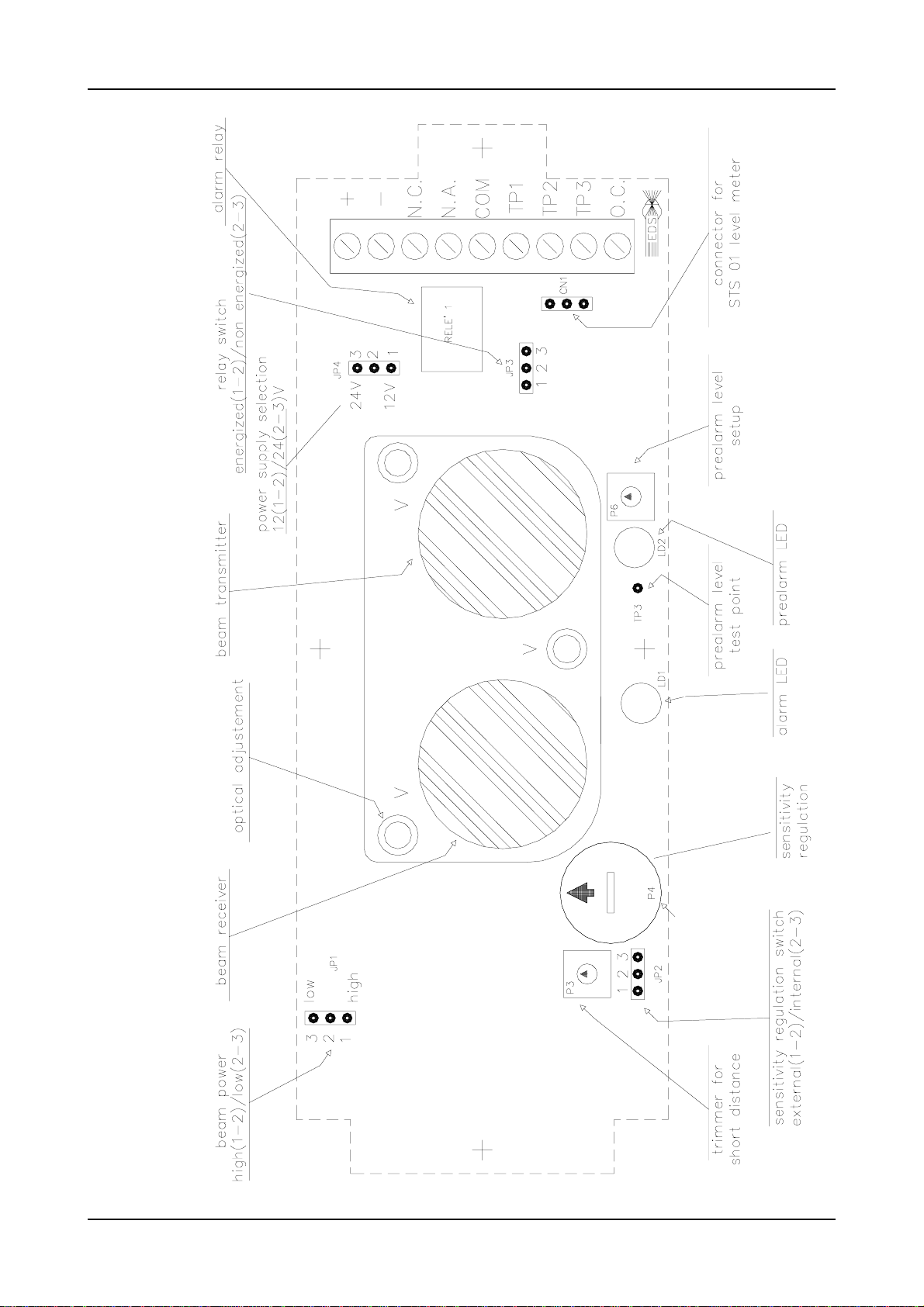
a) Shift the JP2 jump to position 2-3 and rotate
the P4 internal trimmer for the sensitivity
regulation fully clockwise (to the highest
sensitivity). See P4 trimmer in the scheme fig. 8.
b) Place a lamp that can emit a concentrated
and sufficiently brightbeamin frontof thereflector
(werecommendourLAL02 lamp - power supply:
battery 12V-6Ah). Point the lamp beam at the
trasmitter lens (see fig. 3).
c) Observe the screen which is behind the lens
inside the transmitter(right lens) from the lateral
window. You will see a bright point representing
the lamp image.Adjust the transmitter's direction,
using the proper B screws and the key included,
sothatthebrightpoint laysright inthe center,where
there's a small hole through which you can see the
photodiode.It’s importantthat thebright point falls
exaclyin the center of the photosensitive element.
This area is represented by a small dark square at
the center of the photodiode (see fig.4). With this
procedurethedevice will be optically aligned with
the reflector.
5 - SETUP
5.1 - Power up the device. If the previous optical
alignementoperations havebeen carefully carried
out, the following conditions must be found:
internal red LED light switched off
internal yellow LED light switched off
alarm relay R not powered or powered.
This depends on the position of the JP3 jump (see
fig. 8)
buzzer or LED connected to the OC output
terminal not powered (see fig. 9)
voltage at terminal TP1 (see 3.1) higher than 3 V
5.2 - Looking at the instrument's measure
(connected between TP1 and negative terminal)
adjustthe V screws slowly to obtainthe maximum
output signal. If this operation is not sufficient to
obtain a good output, it means that the optical
alignment with the reflector has been done
incorrectly.
5.3- The transmitter emits a conic beam, whose
form and size related to the distance between the
transmitter and the reflector, are shown in the
figures 5 and 6. It is important that the reflector is
inthe center ofthebeam emitted bythe transmitter,
because in these conditions, even if some small
movements of the wall or surface on which the
device is assembled occur (caused by the strains),
the reflector always remains inside the beam. To
obtainthis, the delicatetruing operation withsignal
measure as decribed in points 4.1and 5.2, must be
carried out with the greatest care.Attention: since
the device bases its working on the reflection of
the emitted beam, this reflection must be realized
only by the FX reflector, not by other elements.To
makesurethat this result is obtained, thereflector
mustbe obscuredbya not-reflecting panel.In this
case the instrument (connected between TP1 and
negative terminal) must indicate a voltage under 2
V (read further instructions).
5.4-Adjustthe sensitivityoperatingon P4 trimmer
and remembering what follows:
highsensitivity isobtainedwith signalsbetween
3 and 5V (between TP1 and negative terminal)
medium sensitivity is obtained with 5-8 V
low sensitivity is obtained with 8 V or more
Remember that the adjusted signal is subjected to
a lowering of about 1 V when the device cover is
assembled, due to the frontal mask absorption.
Therefore the signal must be increased of about
1 V to be obtain a perfect adjustment.
5.5 - The sensitivity is to be adjusted according
to the environmental situation. Normally the level
is set for a medium sensitivity, but in case of dusty
environments (furniture factories, ecc) it is better
to use a lower sensitivity (8 V and over).
5.6- Thedeviceisfactoryset toworkwith normally
notpoweredrelays. If you wish to have the opposite
situation operate on the JP3 jump as follows:
pos. 1-2 normally powered relay
pos. 2-3 normally not powered relay
Remember that in pos. 2-3 the device
comsumptionpassesfrom14mAto28mA.
6-WORKINGTEST
6.1 - Verify the detector's working putting a not
reflecting panel in front of reflector.As soon as
the signal drops under the treshold level of
prealarm (3 V), the yellow LED must flash.

4
EDS-TECHNICALINFORMATION
Ifyouletthesignaldrop under the alarm threshold
level (2 V), after a 6" delay the red LED must light
up and the alarm relay must be powered.
7-SETTINGTHE DETECTOR FOR HIGH
SENSITIVITY
7.1 -You can let RK75R detector work at an even
higher sensitivity than the one given above (3-5
V). In this case it is necessary to act as follows:
measure the voltage between the negative
terminal and the test point TP3, which is near
by prealarm led LD2 (see fig. 8), with a 10 V
full-scale high impedance voltmeter
themeasuredvoltagewillbe3V(factoryadjusted)
adjust the P6 trimmer to obtain a voltage from
3 V to 2,2 - 2,5 V
adjust the P4 trimmer in such to obtain a 2,7-3
V between TP1 and negative terminal.
Anyway,becareful,becauseinsuchconditionseven
a little drop of the signal is enough to generate an
alarm.Iftheenvironmentalconditionsarefavourable,
thehighstabilityofthedetectorcircuitsallowsavery
goodperformanceeven insuchlimitconditions.
8 - SETTINGTHE DETECTOR FOR
SHORTDISTANCE
8.1 - If the RK75R detector works on a short
distance , in some cases the JP1 jumper must be
shifted to the pos. 2-3, to reduce the emitted beam
power and to get a good adjustment. In this case
we have a power reduction of about 50%.
Thereforewehave:
pos. 2-3 power reduced of 50%
pos. 1-2 nominal power
Inthisoperationdon’tgivesatisfactoryresultsitisbesides
possibletodoafineadjustmentusingtheP3trimmer:
- counterclockwise the signal between TP1 and
negative terminal reducesgradually
- clockwise the signal increases
We suggest to do this adjustment only if stricly
needed.9- REMOTE DETECTOR CONTROL
9.1- The remote adjustment of the sensitivity can
be adequately done using the optional modules
EV570 (electronic voltmeter) and EV450
(piezoelectricbuzzer),remote connected as shown
TECHNICALDATA
Power supply: 12/24 Vcc (-10+20%)
Protectionagainst inversion of polarity
Current: 10 mAwith normally de-energizedalarmrelay, 25mA
withnormally enegized alarm relay
sensitivity adjustment:with internal trimmeror remote (withthe
accessory EV570)
red LED for the indication of alarm
redYELLOW for the indication of prealarm condition
output alarm realy: 1A/24 V cc
prealarmoutput:(OpenCollector-transitorNPN)50mAoutputmax
trimmer for the regulation of the prealarm trigger point
opticalcapacity
0-25 m. with reflector FX/01
0-20 m. with reflector FX/04
0-40 m. with reflector FX/02
0-30 m. with reflector FX/05
detected area: max 600 mq
protectionclass: IP50 (IEC 529-144)
dimensions:162x62x63mm
plastic box (base red or black a choise - cover black)
weight:250 gr.
9- REMOTE CONTROL
in the schematic of fig. 9
9.2 - If you want to have the remote adjustment of
thesensitivitydon’tforgettoshifttheinnerJP2iumper
from pos. 2-3 to pos. 1-2. In this way the internal P4
trimmer for the sensitivity adjustment, is turned off
andtheoutputterminalsTP2-TP3fortheconnection
with the external trimmer assembled on the module
EV570 (see fig. 9) are switched on.
10-MAINTENANCE
10.1 - the RK75R detector needs a simple and
periodic maintenance. It can be programmed or
madeautomatic with thesuitablesignal given from
thethe detector.When the RK75R goesin prealarm
condition, it outputs the following prealarm signal
activatingofthestatic output OC PRE-AL (OPEN
COLLECTOR). It's suggested to use this signal
because it gives a precise indication of the need
ofmaintenance.
10.2 - the maintenance operations are the
following:
cleaning of the plastic cover of detector. It is
suggested to use a cloth dampened with water
and some little drops of soap. Never use alco-
ol, ammonia and others similar products.
control an tight the internal terminals block.
controltheopticalaligmentbetweenthetrasmitter
and receiver if the surface or the wall on which
theyaremounted, is subjecttodeformation.

5
EDS-TECHNICALINFORMATION
ACCESSORIESFORRK75R
FX01 Round reflector
diam.85 mm. Optical
capacity 0-25 m
FX02 Two round
reflectors with support by
anodised
aluminium.Optical
capacity0-40m.
Dimensions:180x90mm.
FX04 Plane reflector
with good aesthetics.
Support by anodised
aluminium.Optical
capacity max 20 m.
Dimensions:176x60mm.
FX05 Planereflector with
goodaesthetics.Supportby
anodised
aluminium.Optical
capacity max 30 m.
Dimensions:186x80mm.
STS01 Instrument for the
measuring of signal. It can
be assembled in the
internal circuit during the
opticalalignment.
SC05 Plastic boxes to
lodge2modulesEV570or
EV450.Dimensions:
97x55,5mm.
EV570 This module allows
to obtain:
- the remote measuring of the
detector RK70R signal
- the remote signaling of the
detector prealarm condition
- the remote set point of the
detector sensitivity.
Dimensions:107x25x42 mm.
EV450 This module signals
acoustically the coming into a
prealarm condition of one or
more RK70R detectors.
Dimensions:107x52x42 mm.
LAL02 Lamp for optical
alignment. The RK70/R
detectors must be aligned with
the reflector. This lamp is able
to realized an optimum
alignment. The operation is
simple and it assure the most
functionality of detectors. The
LAL/02 is provided of cable
L.=15 m with tweewers for the
connectionto a battery 12V for
the power supply.

6
EDS-TECHNICALINFORMATION
fxrk70
fig. 1
fig. 2
fig.5
fig. 6
fig. 7
fig. 3
beam diameter [cm]
distance [m]
infrared emitting area
screen hole
white screen
fig. 4
RK70R
RK75R

7
EDS-TECHNICALINFORMATION
Fig. 8
INSIDE VIEW

8
EDS-TECHNICALINFORMATION
fig. 9

9
EDS-TECHNICALINFORMATION
The example shows the connection among nr. 5
RK70R - RK75R and the alarm station.
Furthermoreitisindicatedthe connection with the
modulesEV570(electronic voltmetre) and EV450
(piezoelectric buzzer) allowing.
- visualization of the signal level measure
- the sensitivity remote adjustment
- the remote indication of the detector prealarm
conditions
fig. 10
The modules EV570 (electronic voltmeter) show
the signal level and permits the sensitivity
adjustmentof thedetectors towhichit isconnected.
The module EV450 (piezoelectric buzzer) gives
an acoustical signal when one of the detectors in
prealarm condition. This module can control 5
detectors at the same time.

10
EDS-TECHNICALINFORMATION
fig. 11
The example shows the connection among 10
RK75R detectors the alarm station and the
accessories ( modules EV570 and EV450)
Note thatevery 5 detectorsis connectedamodule
EV450

11
EDS-TECHNICALINFORMATION

12
EDS-TECHNICALINFORMATION
RK75RSMOKE DETECTOR
DETECTEDAREA
b - roof with shed beams
2- The given limitscanbe subjected to variations
accordineto theenvironmentalcharacteristicsand
the requested quickness of intervention:
1-The smoke detector RK75R has the following
maximun limits relative to the protected area.
- lenght: mt. 40
- width: mt. 15 (in order to obtain shorter
intervention times mt. 10 are advisable)
- protected area: 40x15 = 600 sq. mt.
In this particularly favourable case the covered
width M can be max mt. 20 and the detector is to
be installed in position A.
If the room is higher than mt. 8 from the ground
(e.g. mt. 12,20), it’s advisable to install another
detector in a lower position
Ex: vault height P = mt. 20
position A H1 = 20-1 = mt. 19
position B H2 = mt. 7
a - vaulted roof
The max covered width M must be = mt. 15. The
detector is to be installed in position A at least
mt. 30-50 under the beam, that is:
H = Q - 30 (cm)
c - roof with regular beams
The same comments as in b case are valid
d - flat roof
The contained informations in this document have been carefully valued
and are reliable. In every case the EDS company doesn't assume
responsibility for possible inaccuracy and she reserve the right to
perform changes in any part of this document and/or product, to improve
the quality, reliability or the design.
Anexampleofinstallation
Data: structure of indutrial shed
- length: mt. 40
- width: mt. 30
- roof height: mt. 6
- kind of roof: flat
Two detectors installed as show in the picture
are requested
Themax covered widht Mis mt. 15. Thedetecors
is to be installed in position A, at least cm. 30-
50 from the roof.
A
B
Table of contents
Other EDS Smoke Alarm manuals