Edsyn Soldavac TSX70 User manual

EDSYNÆINC. PHONE(818)989-2324 FAX(sales):818-997-0895 FAX(service):818-997-0460
instruction manual
Hot Gas + Hot Tip
Desoldering
MADE
IN
U.S.A.
SMT Reflow Vacuum
Workstation
ï COMPLIES WITH MIL-S-45743E, MIL-STD-2000, DOD-STD-2000-1B,
WS6536E AND ESD SPEC, DOD-STD-1686, DOD-HDBK-263
TSX70

TSX70
Solder-Handling Station
(Hot Gas & Hot Tip Desoldering)
Static Safe
Table of Contents
1. Specifications
2. Features
3. Connection & Hook-up
4. Operation
5. Hand Tool Adjustments
5. Tip Replacement
6. Cleaning & Maintenance
7. Calibration
8. Spare Parts Hand Tool
10. Spare Parts Power Supply
SPECIFICATIONS
ï 120V, 60 Hz, 39W - 330W
ï Weight; Power Supply: 6.2 lbs. (2.8 kg)
Hand Tool: 13.5 ozs. (383 g)
ï Temperature range of 400∞F to 800∞F (205∞C-425∞C).
ï Flow is 22 SCFH (11 Li/min) @ 80 psi, 19 SCFH (9 Li/min) @ 65 psi.
ï Voltage leakage from tip to ground, less than 2 MV.
ï Tip to ground resistance, less than 2 ohms.
ï COMPLIES WITH MIL-S-45743E, MIL-STD-2000, DOD-STD-2000-1B
WS-6536E and ESD SPEC, DOD-STD-1686, DOD-HDBK-263.

(B
C)
A)
E)
F)
G)
D)
ï Tool should be place in
Holder when not in use.
ï Hot Gas flow will stop if Tool
is placed in the Holder.
DAMAGED CORD SHOULD
ONLY BE REPLACE BY AN
EDSYN-CERTIFIEDTECHNICIAN
Hand Tool
FEATURES
A ) Gas Heater.
B) Desoldering Head Housing.
C) Desoldering Tip.
D) 24V Power Input, turn clockwise to engage.
E) Gas Connector, turn clockwise to engage.
F) Vacuum Line, connect to AFX73.
G) Trigger, activates vacuum.
H) Cleaning Tool.
Power Supply
FEATURES
(A
(C
(F
(J
(H
(M
(B
(E
(D
(I
A ) Tool Pod, equipped with micro-switch to activate gas & vacuum.
B) Gas Flow Control in standard cubic feet per hour delivered to
Desoldering Tip.
C) Power Switch, to activate WorkStation.
D) Temp. Control Knob, Heater for Desoldering.
E) Temp. Control Knob, Heater for Gas.
F) SH232 Sponge Holder, with cleaning sponge.
G) Gas Output, controlled flow.
H) Power output, 24V, controlled
I) WT623 Tip Wrench
J) AFX73 Filter, NOTE VACUUM FLOW DIRECTION.
K) Gas Input, color coded sleeve.
L) Shop air input.
M) CSX70 Cleaning Tool
(G
(K
(L
ESD Safe

POINTERS:
ï USE CLEANING SHAFT TO REMOVE
ANY OBSTRUCTION IN THE TIP.
ï ACTIVATE VACUUM IN PULSES
RATHER THAN CONTINUOUS SUC-
TION.
5. When solder reflows,
press Trigger to
desolder.
24VConnector
Gas Line
Temperature
control for Hot
Tip
Air Flow
VacuumLine
1. Turn on Power Switch.
Heater indicator lights up.
Hot Gas & Vacuum will
activate if Tool is re-
moved from the Holder.
Unscrew Cleaning shaft from Cleaning Tool.
Cut-Off Switch
2. Set both temperature
controls to desired tem-
perature. i.e. 600∞F
(315∞C).
3. Adjust air flow to desired
setting
(3 to 5 SCFH).
4. Place Tip close to work-
ing area.
OPERATION
Temperature
control for Hot
Gas
Ideal air pressure input:
60 to 90 psi
413.7 - 620.5 KPA
4.1 - 6.2 bar
Inert Gas Input
(color-coded sleeve): 13
psi max.
5 SCFH
2.4 Li/min.
Gas Line
24VConnector
VacuumLine
Hand Tool Connectors must
be turned clockwise to en-
gage.
CONNECTION
& HOOK-UP

ADJUSTMENT
While Tool is in the
Pod, push handle
down and twist.
Twist until it locks into 1 of it's 4 positions.
Twisting counter-clockwise will permit a 1800
turn. Twisting clockwise will permit a 900turn.
Note: Head Assembly does not make a full 3600turn
Use this wrench to remove
or intall tips
CHANGING TIP
TSX713
Desoldering Tip
INSTALLING:
Tighten this last
Tighten this first
Should be done while the tool is
cool.
REMOVING:
Loosen this first
Lossen this last
adjustment
screws
To tilt the Head Assembly, loosen (2) Adjust-
ment Screws. Tilt the Head Assembly to de-
sired position and retighten screws.
Tip
Cleaning Shaft Handle
Retaining Sleeve
ITISRECOMMENDEDFOR THE
OPERATOR TO REMOVE AND
INSPECTTHE TIP DAILY.
REPLACE TIP THERE IS ANY SIGN OF
CORROSION . DOING THIS WILL
ALSO PREVENT THE TIP FROM
SEIZING ON TO THE HEATER.
Before tightening the Retaining
Sleeve
Check tip alignment by inserting the end of the
Cleaning Shaft handle inside the tip, then tighten
Retaining Sleeve

AF625
OS133
SC525
MS229
FC639
OS130
OS132
LockNut Handle
Cover
Trigger
Place inside Housing & push O-Ring over HT01.
REMOVE GUIDE AFTER USING.
Hook
TSX70 Tool Housing
Place Cleaning Shaft & Tip/O-Ring Guide in HT01 Tube.
SafetyCover
Cleaning Shaft Holder
Spring Seat
OS730
O-Ring Set
To clean wall of Housing, Remove
Mica Sheet.
Rotate Cleaner while pushing in.
Push Cleaner all the way to remove
HT01 Tube.
Remove O-Ring by using the Hook.
HT01
OS133
HT01 & OS133 Replacement
Cleaning the Desoldering Head Housing
O-Rings Replacement
inside Valve Assembly
a) Unscrew Lock Nut at the end
of the Tool Handle.
b) Remove Handle Cover.
c) Slide out Valve Assembly
while placing your finger
over the Spring Seat. BE
CAREFUL NOT TO LET THE
SPRING AND THE SPRING
SEAT SHOOT OUT FROM
THEHOUSING
d) Clean all parts with alcohol
only.
e) Replace OS730 O-Ring Set
(set of 3).
f) Lube new O-Rings with
OL111 O-Ring Lube.
Make sure wires and hoses
are
not pinched or kinked.
CLEANING & MAINTENANCE
1. Replace AF625 Filter.
2. Clean SC525.
3. Clean or replace OS133 if neccessary.
4. Replace MS229.
5. Replace worn-out Tip.
INSPECT OVER-ALL TIP
CONDITIONREGULARLY.

CALIBRATION
NOTE:The TI680 has only one input jack.
Calibrate each heater separately.
For heater A:
1. Using option 1, turn on power and set left
Temperature Control Knob to 400∞F
(205∞C). Allow heater Ato warm up.
2. Adjust LO-Temp. Calibration Pot on the
left side of the station so the TI680 Meter
will read 500∞F (260∞C).
If you are using option 2, adjust pot so
meter will read 640∞F (338∞C)
3. Set Temperature Control Knob to 800∞F
(427∞C).
4. Adjust HI-Temp. Calibration Pot so the
Meter will read 900∞F (482∞C).
If you are using option 2, adjust pot so
meter will read 1120∞F (604∞C)
For heater B:
1. Using option 1, set right Temperature
Control Knob to 400∞F (205∞C). Allow
heater Bto warm up.
2. Adjust LO-Temp. Calibration Pot on the
right side of the station so the TI680 Meter
will read 500∞F (260∞C).
If you are using option 2, adjust pot so
meter will read 490∞F (254∞C)
3. Set Temperature Control Knob to 800∞F
(427∞C).
4. Adjust HI-Temp. Calibration Pot so the
Meter will read 900∞F (482∞C).
If you are using option 2, adjust pot so
meter will read 980∞F (527∞C)
SOLDERING TIPS
TSX715 .09 .55
Focus Nozzle (2.3 mm) (14.0 mm)
TSX713 .05 .43
Small (1.3 mm) (10.9 mm)
TSX716 .02 .80
Round Needle (.5 mm) (20.3 mm)
TSX717 .01 .63
Small Oval Needle (.3 mm) (16.0 mm)
TSX718 .02 .80
Medium Oval Needle (.5 mm) (20.3 mm)
Hole Dia. Length
TC271
for heater A TC383
for heater B
heater A
heater B
TI680 meter
option1
option 2
THERMOCOUPLE
PROBES
LO HI
Removethese.
Then install
thermocouple
probes.
TP476
for heater B
TP475
for heater A
cable sold
separately
IMPORTANT:
User must understand the prin-
ciple of wire probe (option 2). See
Form.800. Procedure may yield dif-
ferent temperatures than noted
above.
HI LO

DESCRIPTION
1SR341 Heater Assy. 24V, Hollow Threaded 1
2SR342 Housing, Hot Gas Heater 1
3SR343 Set Screw 1
4HS304 Low Static Silicone Hose, 3/32 i.d. 2
5HT01 Hot Tube 1
6AC737 Accumulator Bushing 1
8SR007 Nut, Hex, 2-56 3
9SR170 Nut, Hex, Cap, 8-32 1
PART NO.
ITEM
NO.QTY
REQ'D
TSX70-1 ÆSOLDER HANDLING TOOL SPARE PARTS LIST

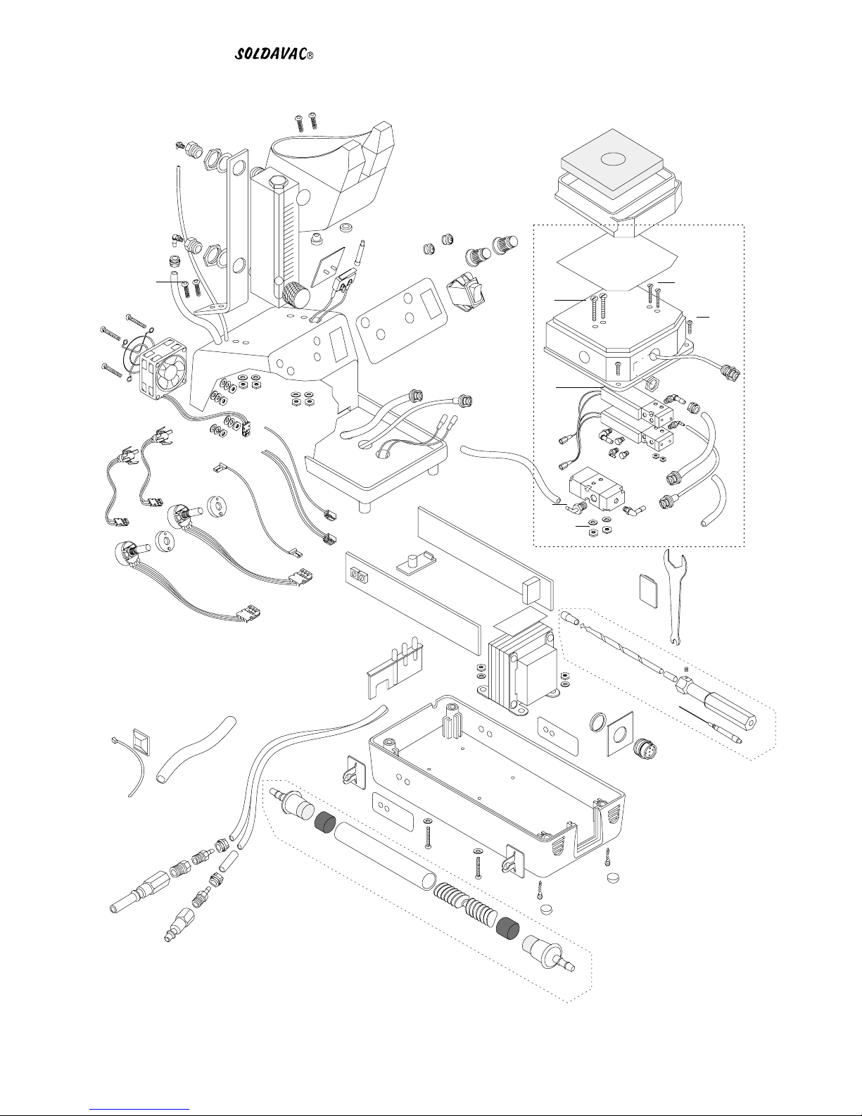
10 SR006 Index Flange (nut side) 1
11 SR122 Screw, Pan Hd, Slotted, 2-56 x 1/8 3
12 SR440 Housing, Desold Head Assy. 1
13 SR345 Screw, Pan Hd, Phillips, 4-40 x 3/8 2
14 SR119 Teflon Spacer 1
15 SR120 Heater Element, 24V, 70W 1
16 SR117 Teflon Bushing 1
17 SR118 Heater Restrainer 1
19 OS731 O-Ring for Heater Bushing and End Cap 2
20 OS133 Silicone Washer 1
21 SR145 Teflon Braided Fiberglass 2
22 RSX72 Retaining Sleeve for Heater Assy. 1
23 TSX713 Desoldering Tip 1
24 SR629 Head Shaft 1
26 SR126 Washer, Nylon 2
27 SR121 Grounding Wire 1
28 SR005 Index Flange (screw side) 1
29 SR169 Washer, Flat, .32 O.D. x .17 I.D 1
30 SR008 Screw, Flat Head, Slotted, 2-56 x 1 2
31 SR168 Screw, Pan Head, Phillips, 8-32 x 1 1
32 SC525 Solder Cone 1
33 AF625 Felt Filter (set of 10) 1
35 SR148 Housing for End Cap 1
36 OS132 O-Ring for Elbow Connector of End Cap 1
37 SR147 Elbow Connector of End Cap 1
38 MS229 Mica Sheet 3
39 SR128 Trigger 1
40 SR348 Gas Tube 1
41 SR349 Handle Base 1
42 SR125 Spring for Head Shaft 1
43 SR127 Retaining Nut for Head Shaft 1
44 SR129 Valve Housing 1
46 OS730 O-Ring Set for Valve Assy. (3 O-Rings) 1 set
48 SR130 Poppet (O-Ring included) 1
49 SR131 Spring 1
50 SR132 Seat for Spring 1
51 SR350 Handle Cover 1
52 FC639 End Cap Assy. 1
55 SR352 Fitting, Quick Disconnect, Female 1
56 HL603 Hose, Low Static Silicone, 3/16 i.d. 5"
57 SR353 Plug, Male Cable Connector 1
60 SR393 Retaining Nut for Handle 1
62 SR143 Wire Guide, 3/8 Length, Nylon 2
68 SR335 Valve Assy. 1
69 SR356 Hose and Wiring Assy. 1
PART NO.
QTY
REQ'D
DESCRIPTION
ITEM
NO.

TSX70-2 ÆSOLDER HANDLING TOOL SPARE PARTS LIST
71
62
92
1
3
31
72
58
53
11
66
85
14
22
74
75
26
27
76
2
6
29
30
77
78
56
57
65 63
33
32
23a
23
97
93
94
96
12
72
93
94
50
61
16
34
51
52
48
38
39
105
70
60 59
24
9
90
91
90
80
84
55
54
83
19
8
7
25
91
19
82
18
19
89
81
44
68 67
95
69
21
15
98
17
36
37
100
102
106
107
108
109
110
111
113
112 99
104
101
103
88
42
9
97
64
5879 51
28
73
20
18
4
87
19
9
35
13
10
5
114

1SR408 Solenoid & Vacuum Ejector Assy. 1
2SR068 Knob, Temperature Control, Front Panel 2
3SR376 Tool Pod, Holder for Hot Gas Tool 1
4SR375 Flow Meter 1
5SR443 Mounting Bracket for Flow Meter 1
6SR065 Power Switch 1
7SH232 Sponge Holder 1
8RS199 Cleaning Sponge 1
9LC363 Locking Sleeve for 1/4" Hose (set of 5) 4
10 HB357 Hose Barb Fitting, 1/8 i.d. 1/8-27 NPT 2
11 SR377 Fitting, Quick-Diconnect Air Input, Male, Long Nose 1
12 SR378 Hose, 1/8 i.d. Twin Tubing Polyurethane, Black (sold per foot) 6 ft.
13 SR379 Reducer, Fitting, 1/4 to 1/8 1
14 SR380 Label, Front Control Panel 1
15 SR310 Label, Temperature, External Calibration, Right Side 1
16 SR311 Label, Temperature, External Calibration, Left Side 1
17 SR351 Hose, 1/16 i.d. Polyurethane, Black (sold per foot) 15"
18 SR381 Elbow Connector, 1/16 i.d. 10-32 UNF (set of 3) 3
19 SR382 Elbow Connector, 1/8 i.d. 10-32 UNF (set of 3) 4
20 SR383 Reducer, Fitting, 1/4-18 npt to 10-32 UNF (set of 3) 2
21 SR384 Screw, Button Head, Socket, 8-32 x 1/2 2
22 SR385 Screw, Button Head, Socket, 8-32 x 5/8 2
23 SR386 Power Cord Assy. w/ Fuse and Connectors 1
23a SR026 Power Cord Only 1
24 SR418 Vacuum Generator, Micro-Ejector, Single/Double Step 1
25 SR115 Retainer Plate for Micro Switch 1
26 SR113 Micro Switch, Tool Holder 1
27 SR114 Push Rod For Micro Switch 1
28 SR419 Solenoid Valve, 24V, Normally Close, 4-Way 1
29 SR431 Washer, Flat, .#10 4
30 SR388 Nut, Hex, 8-32 4
31 SR246 LED Assy. Green, Lens Included 2
32 SR243 Potentiometer Assy. 5K 2
33 SR255 Spacer, 1" Dia. For Potentiometer 2
34 SR387 Transformer, 24V, 4-Pt. Mounting 1
35 SR106 Fuse, Pigtail, 250V, 3A 1
36 SR370 Connector, Parallel, Solderless, Non-Insulated 2
37 SR371 Shrink Sleeve, Clear, 1/4 Dia. (sold per foot) 2"
38 15242W45 PCB Assy. 24V, 45W, 2-Wire 1
39 15242W70H10 PCB Assy. 24V, 70W, 2-wire 1
40 SR432 Housing, VH Connector, 3 Circuit (set of 3) 2
41 SR389 Housing, VH Connector, 2 Circuit (set of 3) 1
42 SR390 Shrink Sleeve, Blue, 3/64 Dia. (sold per foot) 1"
43 SR433 Connector, Flag, Non-Insulated, 22-18 AWG. .187 Tab (set of 5) 7
44 SR437 Connector, Female, Fully Insulated, Red, 22-18 AWG. .187 Tab (set of 5) 2
45 SR436 Receptacle, HR Connector, 2 Circuit (set of 3) 1
QTY
REQ'D
ITEM
NO. DESCRIPTION
PART NO.

46 SR438 Receptacle, HR Connector, 3 Circuit (set of 3) 1
47 SR435 Connector, Flag, Non-Insulated, .250 Tab (set of 5) 3
48 SR434 Insulator, Aramid Paper (1-3/16 x 2-1/2) 1
49 SR400 Ring Tongue Connector, #6, Non-Insulated (5 per set) 2
50 SR011 Screw, Round Head, Phillips, 6-18, Self-Tapping 4
51 SR017 Nut, Hex, 6-32 9
52 SR139 Washer, Star, Lock, #6 8
53 SR144 Screw, Round Head, Slotted, 6-32 x 1/2 4
54 SR420 Connector, Male, Red, Fully Insulated, 22-18 AWG. .187 Tab (set of 5) 2
55 SR401 Screw, Button Head, Socket, 6-32 x 1/2 2
56 SR402 Coupling, Female Quick-Disconnect Fitting, For 1/8 Hose 1
57 SR352 Coupling, Male Quick-Disconnect Fitting, For 1/16 Hose 1
58 SR016 Washer, Flat, #6 4
59 SR421 Nut, Hex. 4-40 2
60 SR422 Washer, Flat, #4 2
61 SR251 Rubber Foot (set of 4) 4
62 SR423 Screw, Flat Head, Phillips, 4-40 x 1 2
63 HS307 Hose, Low Static Silicone, 1/8 i.d. (sold per foot) 9"
64 SR403 PCB Assy. Power Supply Board For Cooling Fan 1
65 SR404 Top Cover, w/ Threaded Insert, For Power Supply 1
66 SR405 Bottom Base, For Power Supply 1
67 SR406 Connector, DIN, Female, Socket, 5-Pin Circular 1
68 SR430 Plate, Molded Frame For Connector 1
69 SR241 Strain Relief for Power Cord 1
70 SR424 Elbow Connector, 3/16 i.d. 1/8 NPT, For 1/8" Hose 1
71 SR409 Label, Cleaning Instruction For TSX70 1
72 SR439 Clip, Holder for Tools and Accessories, Self-Adhesive 4
73 AFX73 Air Filter Assy. Flux Condenser 1
74 SR410 Spacer, Flat, For Tool Pod, Back Side 1
75 SR411 Spacer, Flat with Stem, For Tool Pod, Front Side 1
76 SR412 Screw, Round Head, Slotted, 6-32 x 1.25 4
77 SR413 Fan Guard, Grill For Cooling Fan 1
78 SR414 Fan Assy. 12V w/ Connector 1
79 SR366 Washer, Split, Lock, #6 2
80 SR425 Coupling, Male, Quick-Disconnect for 1/16 Hose (Panel Mount) 1
81 SR426 Plug, Hex. 250 Dia. 2
82 SR427 Coupling, Female, Quick-Disconnect, 1/16 Hose 1
83 SR428 Coupling, Male, Quick-Disconnect, 1/8 Hose 1
84 SR008 Screw, Flat Head, Slotted, 2-56 x 1 2
85 SR416 Holder, Wrench Hanger, Self-Adhesive 1
86 SR415 Terminal, Crimp for VH Connector (10 per bag) 10
87 SR229 Medallion, EDSYN Logo, Self-Adhesive 1
88 HB359 Fitting, Quick-Disconnect Air Input, Male 1
89 SR007 Nut, Hex. 2-56 2
PART NO.
QTY
REQ'D
DESCRIPTION
ITEM
NO.

90 SR283 Hose, 1/8 i.d. Polyurethane, Black (sold per foot) 2.5"
3.5"
91 SR429 Hose, 1/16 i.d.Polyurethane, Clear (sold per foot) 1.5"
3.5"
92 SR417 Cover for Solenoid & Vacuum Ejector Assy. 2
93 AF629 Felt Filter (set of 10) 2
94 AF040 Foam Filter (set of 10) 2
95 SR304 Flux Condenser, Cooling Fin 1
96 SR305 Barrel, Filter Housing 1
97 SR266 End Cap for Filter 2
98 CSX71 Cleaning Shaft for Soldering Tip 1
99 CSX70 Cleaning Tool for Solder Debri Removal (CSX71 included) 1
100 SR307 Drill, Cleaner and Hook 1
101 SR308 Set Screw, 10-32 x 3/16, Socket 1
102 SR309 Cover for Drill and Hook 1
103 SR444 Bushing, 1/4 O.D. x 3/4 Length, Stainless Steel Tubing 1
104 SR306 Handle for Cleaning Tool 1
105 WT623 Wrench for Soldering Tip 1
106 SR442 Wire, White, 24 AWG (sold per foot) 4"
107 SR445 Wire, Black, 22 AWG (sold per foot) 12" 3@
10.5" 2@
4.5" 2@
2" 3@
108 SR446 Wire, White, 22 AWG (sold per foot) 12" 2@
4.5" 2@
11.5"
15"
109 SR447 Wire, Red, 22 AWG (sold per foot) 12"
110 SR448 Wire, Green, 18 AWG (sold per foot) 5"
111 HS320 Hose, Low Static, Silicone, 1/4 Dia. (sold per foot) 3"
112 SR050 Cable Tie (set of 5) 7
113 SR051 Mount for Cable Tie (set of 2) 1
114 SR126 Washer, 5/8 i.d. Nylon 2
PART NO.
QTY
REQ'D
DESCRIPTION
ITEM
NO.
46
45
40 47
43
49
41
86
Connectors

EDSYNÆINC. PHONE(818)989-2324 FAX(sales):818-997-0895 FAX(service):818-997-0460
THE NAMES LONER, SOLDAPULLT, SOLDAVAC, ATMOSCOPE
AUTO-VAC, IDLE-REST, OCTAVAC AND KLATCH
ARE REGISTERED TRADEMARKS OF EDSYN, INC.
MOST PRODUCTS ARE COVERED BY U.S. AND
FOREIGNPATENTS ANDPENDING APPLICATIONS.
DESIGN, COLOR AND MATERIALS
SUBJECT TO CHANGE WITHOUT NOTICE.
TIP STYLE ON SOLDERING, DESOLDERING AND HOT AIR TOOLS MAY VARY.
PRINTED IN U.S.A.
ALL RIGHTS RESERVED.
NO PART OF THIS PUBLICATION INCLUDING THE INDIVIDUAL ICONS
MAY BE REPRODUCED OR UTILIZED IN ANY FORM OR BY ANY MEANS
WITHOUT THE PERMISSION OF EDSYN, INC.
15958 Arminta Street, Van Nuys, CA 91406-1896
Intellectual
Property
©Copyright EDSYN, Inc. 1998
Other manuals for Soldavac TSX70
1