Pace TF 1700 User manual

TF 1700 and TF 2700 BGA Rework Station
Operation and Maintenance Manual
Manual Number 5050-0554
PACE TF 1700
PACE TF 2700

System Operations Manual
www.paceworldwide.com Page 2 of 50
Table of Contents
Packing Contents, Standard Items..................................3
Specifications ..................................................................3
Parts Identification...........................................................4
Safety Information ...........................................................5
Features..........................................................................5
Set-Up.............................................................................7
Connect ................................................................7
Start up.................................................................8
Inserting vacuum Changing nozzle pick ...............8
Inserting nozzle.....................................................8
Set up screen features..........................................9
Alignment screen features..................................10
Production screen features.................................11
Production Mode Record Manager.....................11
Profile development screen features ..................13
Inspection screen features..................................16
Calibration...........................................................20
Operation.......................................................................23
Production...........................................................23
Component removal ...........................................26
Profile development............................................26
Temperature Control .....................................................28
Maintenance..................................................................28
Heater Replacement......................................................30
Adjustments and Alignments.........................................37
Regulation.....................................................................41
Service and Warranty....................................................41
Contact Information.......................................................42
NOTE:
This manual uses much of the TF1700 to demonstrate the features of the
PACE BGA workstations. While most of the features are the same, the
preheater array is unique to the TF 2700.

System Operations Manual
www.paceworldwide.com Page 3 of 50
Packing Contents, Standard Items
Description PartNumber
TF 1700 8007-0465 (120V)
8007-0466 (230V)
TF 2700 8007-0467 (120V)
8007-0469 (230V)
PC -
Monitor -
Keyboard -
Mouse -
Pick Vac 7027-0001-P1
Vacuum Pick Kit 6993-0276
Suction Cups 6993-0202-P1
Alignment Board 4018-0100-P1
Mounting Platform Stencil 1321-0725
Mounting Platform Flux Dip 1321-0735
Hot Grip Removal Pad 1100-0307
Thermocouples (4) 1340-0174-P1
Hex Wrench Kit 6016-0034
Power Cord 1332-0224
Video Cable 3008-0168
1. Specifications:
Part Number 8007-0465
8007-0466 (EXPORT)
Dimensions 737 mm H x 686 mm W x
737 mm D (29” x 27” x 29”)
Weight (w/o computer) 45 kgs (100 lbs)
Power Requirements 115 VAC, 60 hz or 230 VAC,
50 Hz 2000 watts
PC Pentium 4, 256M Ram, 3.5
Floppy Drive, CD
Top Heater Adjustable convective air (air
or N2), Maximum 20 SLPM,
1200 watts 100 to 400 °C,
212 to 750 deg °F
Bottom Heater IR, 400 watts,
100 to 221 °C, 212 to 430
deg °F
Vacuum 5.9 inHg
Optics High resolution, Vision
Overlay System
Positioning Accuracy
(Z travel) +/- 25 umeters (0.001”)
Video 2 Composite Video
(external)
1 “S” Video (Internal)
15” Integrated color Flat
Panel Monitor
PC Board Size 305 x 305 mm, 12” x 12”
Component Nest Size
(Optional) 65 mm x 65mm, 255” x 2.55”
max. See warning on page
24
TF 1700
Part Number 8007-0467
8007-0469 (EXPORT)
Dimensions 737 mm H x 686 mm W x
737 mm D (29” x 27” x 29”)
Weight (w/o computer) 90 kg (200 lbs)
Power Requirements 115 VAC, 60 hz or 230 VAC,
50 Hz 2600 watts
PC Pentium 4, 256M Ram,
Floppy Drive, CD
Top Heater Adjustable convective air (air
or N2), Maximum 20 SLPM,
1200 watts 100 to 400 deg
C, 212 to 750 deg F
Bottom Heater IR, One 400 Watts
IR Six 150 Watts
100 to 221 deg C, 212 to 430
deg F
Vacuum 450 mm Hg
Optics High resolution, Dual Color
Vision Overlay System
Positioning Accuracy (Z
travel) +/- 25 umeters (0.001”)
Video 2 Composite Video (external)
1 “S” Video (Internal)
17” Integrated color Flat
Panel Monitor
PC Board Size 610mm x 610 mm, 24” x 24”
Component Nest Size 65 mm x 65mm, 2.56” x
2.56” max.
TF 2700

System Operations Manual
www.paceworldwide.com Page 4 of 50
TF 1700 BGA Rework Station Parts Identification
Figure 1a
A. Air Flow Meter This device is used to control and monitor the airflow
through the reflow head.
B. Sensor Inputs The sensor inputs are K-type thermo-couples.
Measured temperatures are displayed through the PC
software in real time for use in making profile graphs.
C. LCD Display Monitor Displays PC software.
D. Keyboard Used to enter information into software.
E. Reflow Head Contains the top-side heater and moves up and down
via an electric motor that is controlled through the
software. The reflow head is clutched to control
downward force.
F. Cooling Fan The component and PCB are cooled by the cooling fan,
and can be activated automatically after the reflow cycle
is complete or operated manually.
A
B
F
C
D
E
G
H
I
J
K
L

System Operations Manual
www.paceworldwide.com Page 5 of 50
G. Optics Housing Contains the camera and beam splitter (prism). The
housing extends and retracts automatically during
operation and the lights for the optics will turn on/off
automatically when the housing is extended/retracted.
H. Bottom Side Heater Used to warm the PCB from the underside. It is an IR
type heating source.
I. Board Holder Fine adjustment of both the X and Y direction is
achieved by using the adjusting knobs on the end of the
holder for X and on the front of the machine for Y.
The right side of the holder is spring loaded to hold the
PCB securely.
J. On / Off Switch Used to turn the system on or off. When turning off the
system, always turn off the PC using the windows
interface first. When starting the system, always turn on
TF1700 before starting the PC software.
K. Mouse Used to enter information into software.
L. Emergency Off Switch In case an emergency shut down is necessary, press
this button.
TF 2700 BGA Rework Station Parts Identification
A
B
F
C
D
E
G
H
*Not pictured: PC, Keyboard, and Mouse

System Operations Manual
www.paceworldwide.com Page 6 of 50
Figure 1b
A. Reflow Head Contains the top-side heater and moves up and down
via an electric motor that is controlled through the
software. The reflow head is clutched to control
downward force. through the reflow head.
B. Sensor Inputs Contains the camera and beam splitter (prism). The
housing extends and retracts automatically during
operation and the lights for the optics will turn on/off
automatically when the housing is extended/retracted.
C. Cooling Fan The component and PCB are cooled by the cooling fan,
and can be activated automatically after the reflow cycle
is complete or operated manually.
D. Board Holder Fine adjustment of both the X and Y direction is
achieved by using the adjusting knobs on the end of the
holder for X and on the front of the machine for Y.
The right side of the holder is spring loaded to hold the
PCB securely.
E. Emergency Off Switch In case an emergency shut down is necessary, press
this button.
.
F. Sensor Inputs The sensor inputs are K-type thermo-couples.
Measured temperatures are displayed through the PC
software in real time for use in making profile graphs.
G. Bottom Side Heater Used to warm the PCB from the underside. It is an IR
type heating source.
H. On / Off Switch Used to turn the system on or off. When turning off the
system, always turn off the PC using the windows
interface first. When starting the system, always turn on
TF1700 before starting the PC software.
2. Safety Information
a. Do not contact the Heater or its peripheral parts during operation.
b. Once turned off, let the unit cool completely before contacting. They are hot, you
will get burned.
c. When using fluxes, use fume extraction equipment or use in a well-ventilated
area to minimize operator exposure to fumes.
d. Do not use near combustible vapors.
e. Do not leave the equipment unattended when in use.
f. Do not open rear panel without disconnecting the main power cable.
3. Features
a. The TF 1700 and TF 2700 are ideal for post assembly rework, repair, and low
volume/short run production operations. The TF 1700 and TF 2700 can remove
and install PBGAs, CSPs, FCs, LGAs, LCC’s and other SMDs.
b. Featuring unparalleled thermal performance, PACE BGA Rework Stations
flexibility and state of the art process software means no other system is easier

System Operations Manual
www.paceworldwide.com Page 7 of 50
to use. The TF 1700 and TF2700 are a PC driven, semi-automated system that
requires a Pentium ® 4 PC featuring Windows XP® Professional OS. The unique
standard software package offers much more than just an operator interface.
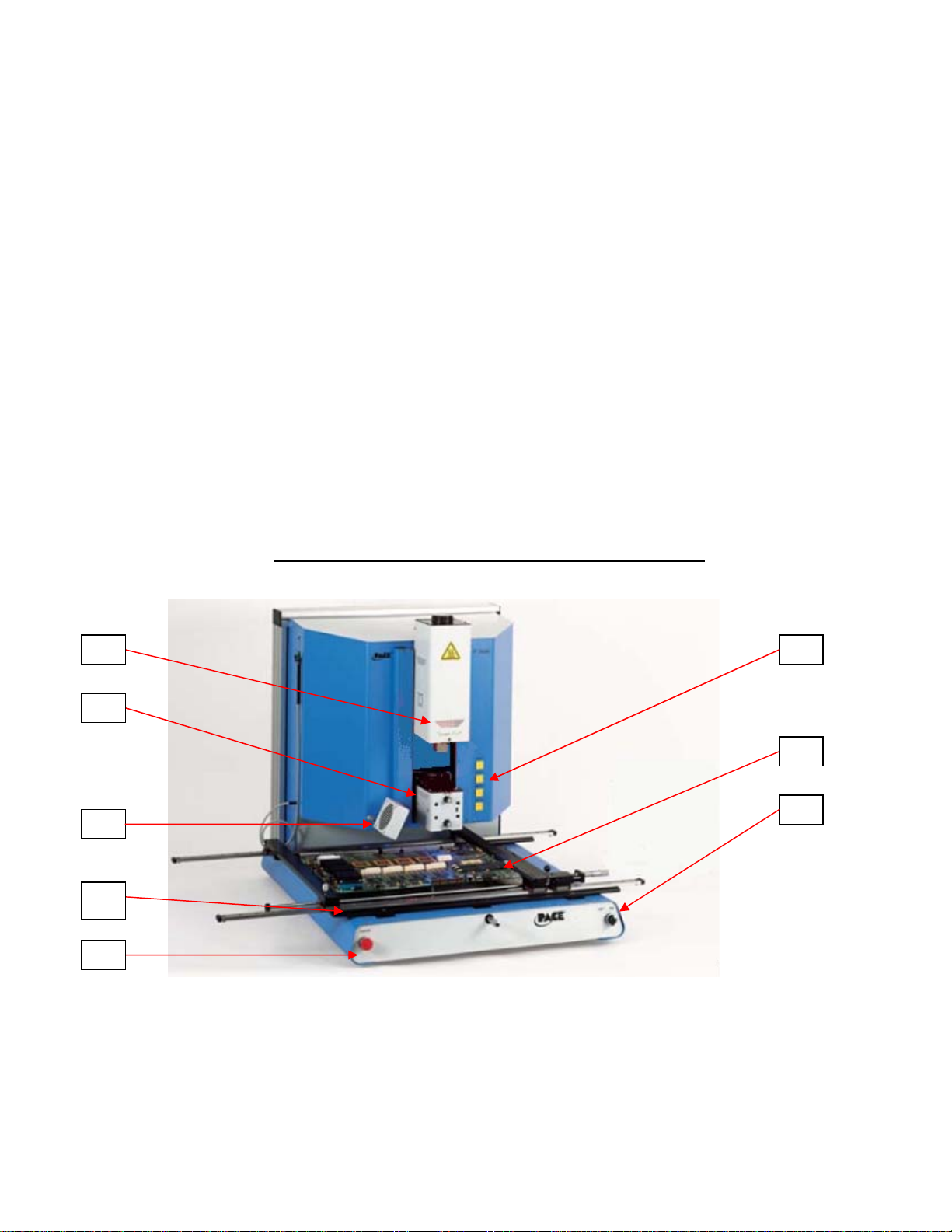
PACE BGA Rework Stations advanced vision and placement system is highly
accurate and can quickly magnify even the smallest components for easy
alignment. TF 1700 and TF 2700 uses a combination of convective top heating
coupled with powerful IR bottom heating for an effective, repeatable heating
process.
c. Economical and easy to use, PACE BGA Rework Systems deliver high-end
BGA/CSP functionality, moving far beyond expensive, bulky rework machines by
offering unparalleled performance at an affordable price.
d. REFLOW FUNCTION
i. Unequalled programmability and process control ensures successful,
repeatable installation.
ii. The powerful and responsive 1200 Watt top heater, with closed loop
temperature control, coupled with proven nozzle design ensures uniform
temperature distribution when heating.
iii. High power bottom heater allow for successful and repeatable reflow at
safe, low temperatures.
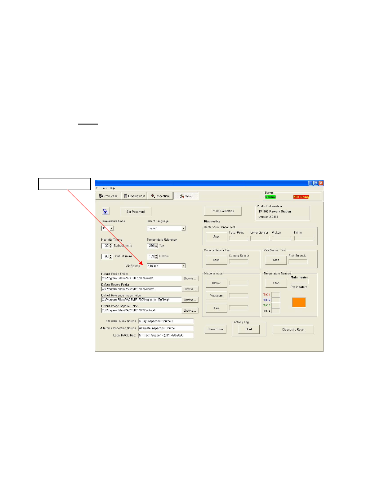
iv. Profiles are programmed through the PC software.
v. Creating the perfect profile is easy with real time adjustment of profile
parameters through the PC.
vi. Store and recall an infinite number of profiles.
vii. Two pre-defined profiles for use as baselines when developing custom
profiles are included.
viii. Self contained, no external air supply or vacuum connections required.
Can also be used with N2from external source.
ix. Semi-automated, motorized reflow head.
x. Four thermo-couple sensor inputs ensure successful profile development
and monitoring.
xi. External fan to cool PCB and component to below solder melt
temperatures after reflow.
e. ALIGNMENT AND PLACEMENT FUNCTION
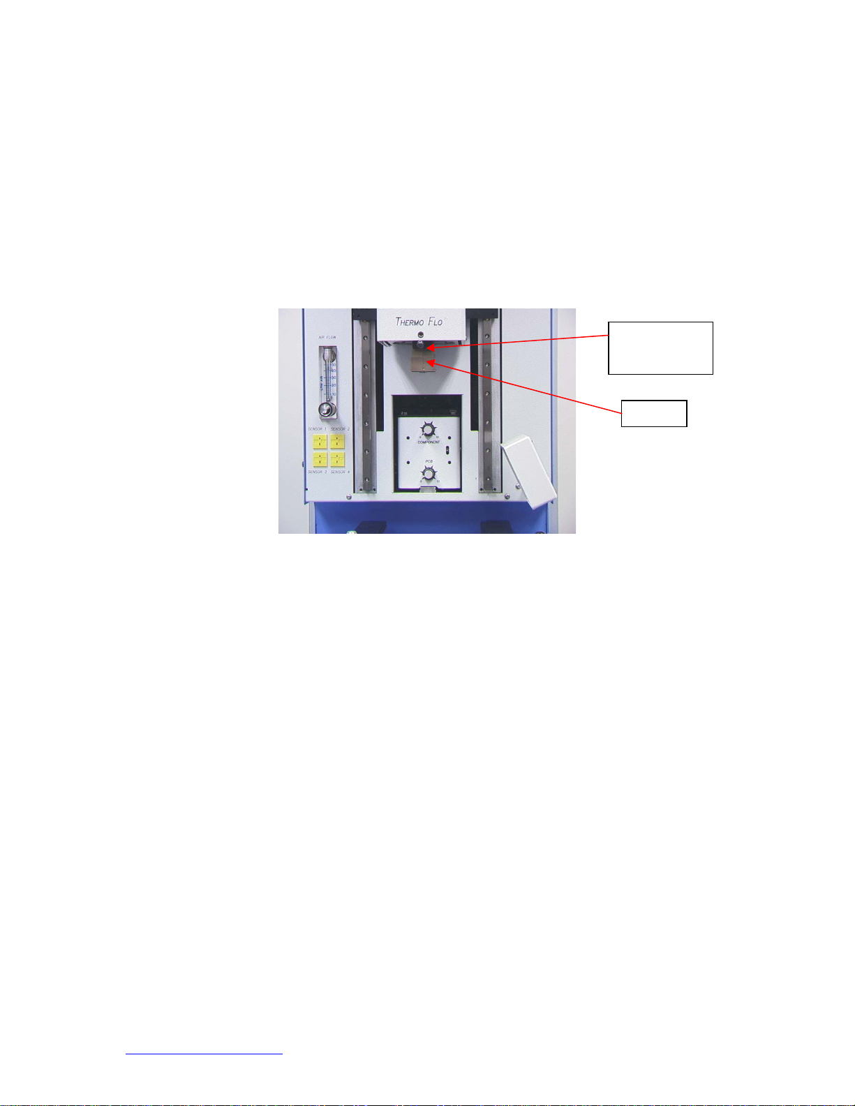
i. The component is held by a precision vacuum placement pick, which is
located within the heater assembly.
ii. High resolution Color Vision Overlay System (VOS) with color camera
and dichroic prism. VOS does not require routine calibration, eliminating
costly downtime and operator frustration.
iii. Color Camera with 72x zoom capability, featuring auto-focus.
iv. Lighting system uses “Ultra Bright” White LEDs for maximum contrast of
lands and solder balls on component.
v. Independent lighting controls for component and PCB to maximize
overlay contrast.
vi. Retractable optics housing protects VOS from dirt and contamination.
vii. Accurately places any array package up to 65mm (2.5") square and as
small as 1 mm (.04”) square.
viii. Precise micrometer adjustment for X, and Y axis with Theta adjustment
ensures placement accuracy.
ix. High-flow vacuum pick holds component securely.
x. Images are viewed through the PC in standard or full screen viewing
options.
f. PRE-HEAT FUNCTION AND BOARD HOLDER

System Operations Manual
www.paceworldwide.com Page 8 of 50
i. Fully adjustable, precision, spring loaded board holder with top or bottom
PCB registration. Precise micrometer adjustment for X and Y adjustment
ensures placement accuracy for repeatability.
ii. Rugged, stable board platform to hold and support the PCB.
iii. Unique board holding fixtures that are able to hold very small and odd
shaped PCBs.
iv. Board supports are standard with the system.
v. Integrated, powerful, IR pre-heater with closed loop temperature control
ensures process integrity by delivering heat evenly, time after time.
4. Set-Up
a. Connect
i. The TF 1700 and TF 2700 come configured to use the internal air pump.
Both BGA Rework Stations may also be operated with an external N2
Supply. Select air or (nitrogen) source using the drop down box on the
setup page. Warning: Do not operate the TF 1700 in N2mode unless N2
supply is connected and on.
N
2Connection
TF-1700 Software shown

System Operations Manual
www.paceworldwide.com Page 9 of 50
ii. Insert PC into brackets on back of BGA Rework Station.
iii. Monitor
1. Connect power cord.
2. Connect video cable to the 9-pin connector of the PC.
iv. Keyboard – connect cable to computer.
v. Mouse – connect cable to computer.
vi. Connect cables between PC and back of BGA Rework Station according
to labels.
vii. Connect power cords to BGA Rework Station and PC.
b. Start up
i. Turn on circuit breaker on back of unit.
ii. Turn on power switch on front of unit.
iii. Turn on computer.
iv. Turn on monitor.
v. Mouse click on software icon.
vi. Read and accept license.
c. Inserting/changing vacuum pick.
i. Insert proper size vacuum pick. The diameter needs to be smaller than
the top of the component. The pick screws into place. (Figure 3a)
Warning: Use of tools to tighten vacuum pick may result in damage
to system. Tighten vacuum pick by hand only.
Vacuum
p
ic
k
N
2Connection

System Operations Manual
www.paceworldwide.com Page 10 of 50
Figure 3a
d. Inserting/changing nozzle. (Figure 3b)
i. Insert proper size nozzle. The OD of the nozzle should be 3 mm larger
than the outside of the component. If the proper nozzle size cannot fit
onto the PCB due to adjacent components being to close, use a smaller
nozzle or keep the nozzle approximately 1mm above the part. Align the
nozzle under the square hole in the reflow head. The nozzle snaps into
place. The nozzle can be positioned with the front surface parallel to the
PCB or at a diagonal by moving the lever on the nozzle housing. To
rotate the nozzle, first loosen the retention screw in front of the housing.
Figure 3b
N
ozzle
Lever to rotate
nozzle

System Operations Manual
www.paceworldwide.com Page 11 of 50
a. Software set up screen features. (Figure 4a)
Figure 4a
i. Set Password. Setup and profile settings can be password protected.
ii. Set Language. Software text language can be changed.
iii. Set temperature for Celsius or Fahrenheit.
iv. Set yellow temperature reference lines on the profile graph.
v. Set setback time. Machine will go into setback after selected idle time.
Setback reduces heater temperatures during extended idle times to
extend heater life.
vi. Set auto shutoff time. Machine will completely shut down after selected
idle time.
vii. Air Source selects internal pump or external N2source.
viii. Default location of saved profile files, records, image, and capture.
ix. Changes title of Video Sources on inspection screen.
x. Shows system communication error.
xi. Initiate prism calibration sequence.
xii. Initiate heater arm sensor test. Checks proper orientation and operation
of heater arm position sensors.
xiii. Initiate camera sensor test. Checks proper orientation and operation of
camera position sensor..
xiv. Initiate pick sensor test. Checks proper orientation and operation of pick
position sensor.
xv. Checks operation of heater blower, cooling fan, and vacuum pump.
i
ii
iii
iv
v
vi
x
xi
xii
xiv
xv
xvi
xvii
xviii
viii
ix
xix
vii

System Operations Manual
www.paceworldwide.com Page 12 of 50
xvi. Temperature sensors. Tests active thermocouple circuitry.
xvii. Reset diagnostics. Must be clicked after any diagnostic test is performed
to reset the tests to default settings.
xviii. Run the activity log.
Figure 4b
Figure 4b shows the pre-heater indicator of the
TF 2700. This feature indicates which pre-
heater is on and the current temperature. To
turn on or off individual secondary pre-heaters
click on the graphic. While individual
secondary pre-heaters can be turned on and
off, they must all be set at the same
temperature. They can be adjusted by
dragging the yellow lines on the graph or
through the profile manager.

System Operations Manual
www.paceworldwide.com Page 13 of 50
b. Alignment Screen Features (Figure 5)
Figure 5
i. Full Screen. Click on here to view image full screen.
ii. Flip Image. Allows operator to flip the image horizontally or vertically.
iii. Component/PCB alignment image. Proper alignment is viewed here showing
the PCB pads directly under the component pads.
iv. Zoom bar. The image can be zoomed in or out using this bar.
v. Focus bar. The image can be manually focused using the slider on this bar or
it can be automatically focused by checking the box by “auto.”
vi. Instructions. Follow these instructions to proceed through the alignment
sequence.
vii. Modify Instructions.
1. Edit – Change current profile instructions.
2. Load – Loads saved profile.
3. Save – Saves changes made to instructions.
4. Reset – Returns to factory set instructions.
viii. Nozzle step adjustment. If component cannot be aligned nozzle height up or
down with this option until better alignment or focus is achieved.
iii
iv
v
vi
vi
viii
ii
i

System Operations Manual
www.paceworldwide.com Page 14 of 50
c. Production Screen Features (Figure 6)
Figure 6a
i. Profile Name. Indicates currently selected profile. A new profile can be
selected from a list of saved profiles by clicking on the arrow.
ii. Record Manager. Profile information may be stored and exported in PDF file
format. See figure 6a
iii. Graph. A saved graph and, if thermocouples are used, an active trace graph
are viewed here.
iv. Fan On/Off Selector. Manual on/off switch for the cooling fan.
v. Status Bar.
1. System status – shows if system is “normal,” in “setback” or “shutdown.”
2. Heater status – Shows “ready” if bottom heater is in range. Shows “not
ready” if bottom heater is not in range. The software will not continue until
it is in “ready” status.
vi. Nozzle Step Indicator. Indicates how many steps the nozzle will lower to
properly position itself for operation.
vii. Abort Button. Click at any time to abort the process and return to the
beginning.
viii. Sequencing Button. Click here to proceed to next step in the operation.
ix. Pre-Heater indicator. Indicates pre-heater is on or off .
x. Sensor indicators. Real-time sensor readings can be viewed here if
thermocouples are used.
xi. Production Mode Record Manager Features (Figure 6c)
ii
iii
vi
vii
viii
ix
x
i
iv
v

System Operations Manual
www.paceworldwide.com Page 15 of 50
d. Profile Development Screen Features (Figure 7)
Figure 6c
Figure 6b
Figure 6b shows the pre-heater indicator of the
TF 2700. This feature indicates which pre-
heater is on and the current temperature. To
turn on or off individual secondary pre-heaters
click on the graphic. While individual
secondary pre-heaters can be turned on and
off, they must all be set at the same
temperature. They can be adjusted by
dragging the yellow lines on the graph or
through the profile manager.

System Operations Manual
www.paceworldwide.com Page 16 of 50
Figure 7a
i. Profile Name. Indicates currently selected profile.
ii. Profile Manager. Temperature and time setting entered by the developer can
be viewed managed here (Figure 7a).
iii. Graph. A saved graph and, if thermocouples are used, an active trace graph
are viewed here.
iv. Fan On/Off Selector. Manual on/off switch for the cooling fan.
v. Status Bar.
1. System status – shows if system is “normal,” in “setback” or “shutdown.”
2. Heater status – Shows “ready” if bottom heater is in range. Shows “not
ready” if bottom heater is not in range. The software will not continue until
it is in “ready” status.
vi. Nozzle Step Indicator. Indicates how many steps the nozzle will lower to
properly position itself for operation.
vii. Abort Button. Click at any time to abort the process and return to the
beginning.
viii. Sequencing Button. Click here to proceed to next step in the operation.
ix. Pre-Heater indicator. Indicates if pre-heater is on or off.
x. Sensor indicators. Real-time sensor readings can be viewed here if
thermocouples are used.
ii
iii
vi
vii
viii
ix
x
i
iv
v
d. Profile Development Screen (Figure 7)

System Operations Manual
www.paceworldwide.com Page 17 of 50
xi. Heater. Click on Heater button during profile development to deactivate
heater.
xii. Cycle Start. Click on button to run profile during development.
xi
xii
TF 2700 Pre-Heater Indicator. Indicates which pre-
heater is on and the current temperature. To turn on
or off individual secondary pre-heaters click on the
graphic. While individual secondary pre-heaters can
be turned on and off, they must all be set at the same
temperature. They can be adjusted by dragging the
yellow lines on the graph or through the profile
manager.
TF 2700 Pre-heater Indicator
Figure 7b
Figure 7c

System Operations Manual
www.paceworldwide.com Page 18 of 50
Profile Development Screen Features TF 1700 (Figure 7d)
i. Profile Name. Indicates currently selected profile.
ii. Profile Parameters. Change each zone temperature and time settings
iii. Use Ramp. Enables or disables ramp phase.
iv. Profile Instructions. Allows operator to make notations and instructions.
v. Mode. Choose Installation or removal mode by clicking.
vi. Placement. Choose manual or automatic while in installation mode by
clicking.
vii. Profile Management. Create, save, or recall profiles.
viii. View selected reference images.
ix. Liftoff. Select from Auto or Manual in removal mode by clicking.
x. Flux Dip. Enable or disable flux dip operation by clicking.
i
ii
iii
vi
vii
viii
ix
x
iv
v
NOTE
The TF 1700 airflow control is manual using the flow meter mounted on
the front housing. The TF 2700 airflow control feature is operated using
the PC software.

System Operations Manual
www.paceworldwide.com Page 19 of 50
Profile Development Screen Features TF 2700 (Figure 7e)
i. Profile Name. Indicates currently selected profile.
ii. Profile Parameters. Change each zone temperature and time settings
iii. Use Ramp. Enables or disables ramp phase.
iv. Profile Instructions. Allows operator to make notations and instructions.
v. Mode. Choose Installation or removal mode by clicking.
vi. Placement. Choose manual or automatic while in installation mode by clicking.
vii. Profile Management. Create, save, or recall profiles.
viii. View selected reference images.
ix. Liftoff. Select from Auto or Manual in removal mode by clicking.
x. Flux Dip. Enable or disable flux dip operation by clicking.
i
ii
iii
vi
vii
viii
ix
x
iv
v
NOTE
The TF 2700 airflow control feature is operated using the PC software.
The TF 1700 airflow control is manual using the flow meter mounted on
the front housing.

System Operations Manual
www.paceworldwide.com Page 20 of 50
e. Inspection Screen Features
Inspection Screen (Figure 8a)
i. Flip feature. Rotate or flip inspection image.
ii. Inspection Image. The inspection image selected is viewed here.
iii. (S) tab allows you to select video input source. (C) tab gives you access to
TF1700 camera control when selected input source.
iv. Focus. Select Auto or Manual Focus.
v. Mode. Allows operator to review library images (Fig 8a), capture images (Fig
8b), review saved images (Fig 8c), and create report (Fig 8d).
vi. Takes a snapshot of the current camera image.
vii. Save Image. Saves captured image to TIFF file format.
i
iii
iv
vi
ii
v
vii
This manual suits for next models
1
Table of contents
Other Pace Rework Station manuals