EDWANZ group DEUTRONIC DVC Series Manual

Deutronicstr. 5, D - 84166 Adlkofen
Tel.: +49 (0) 8707 920-0
Fax: +49 (0) 8707 1004
http://www.deutronic.com
Installation and safety instructions – DVC/DVCH/DR Version: 12.07.2022 Page 1 of 8
Installation and safety instructions
DC Converter – DVC, DVCH, DR series
1.
Instruction ........................................................................................................................................................................2
2.
Symbols ...........................................................................................................................................................................2
3.
Intended Use ...................................................................................................................................................................3
4.
Warranty ..........................................................................................................................................................................3
5.
Unpacking ........................................................................................................................................................................3
5.1
Control before the first commissioning ...................................................................................................................3
5.2
Disposal of the packaging material.........................................................................................................................4
5.3
Storage....................................................................................................................................................................4
6.
Installation........................................................................................................................................................................4
6.1
Requirements for the installation place...................................................................................................................4
6.2
Operating situation..................................................................................................................................................4
6.3
Cooling ....................................................................................................................................................................5
7.
Installation and preparation for the operation ..................................................................................................................5
7.1
Connection ..............................................................................................................................................................5
7.2
Cable routing...........................................................................................................................................................6
7.3
Communication interface ........................................................................................................................................7
8.
General operation instructions.........................................................................................................................................8
9.
Cleaning...........................................................................................................................................................................8
10.
Contact data................................................................................................................................................................8
Deutronicstr. 5, D - 84166 Adlkofen
Tel.: +49 (0) 8707 920-0
Fax: +49 (0) 8707 1004
http://www.deutronic.com
Installation and safety instructions – DVC/DVCH/DR Version: 12.07.2022 Page 2 of 8
1. Instruction
The following installation and safety instructions have to be observed before commissioning a DC Converter of the DVC,
DVCH and DR series (described as device or DC/DC converter in the following).
The user (also referred to as system integrator) is provided with important information to detect existing danger potentials
and to minimize the risk of personal or material damages.
This document does not make any claim to completeness and considers the risks known to the manufacturer.
The operation of the device may only be carried out by qualified and instructed personnel.
The DC/DC converters should be seen as system components. The responsibility for the application of the DC/DC
converter in the application including the risk analysis is subject to the system integrator. Additionally, the model specific
data sheets must always be observed.
This instruction should always be kept easily accessible.
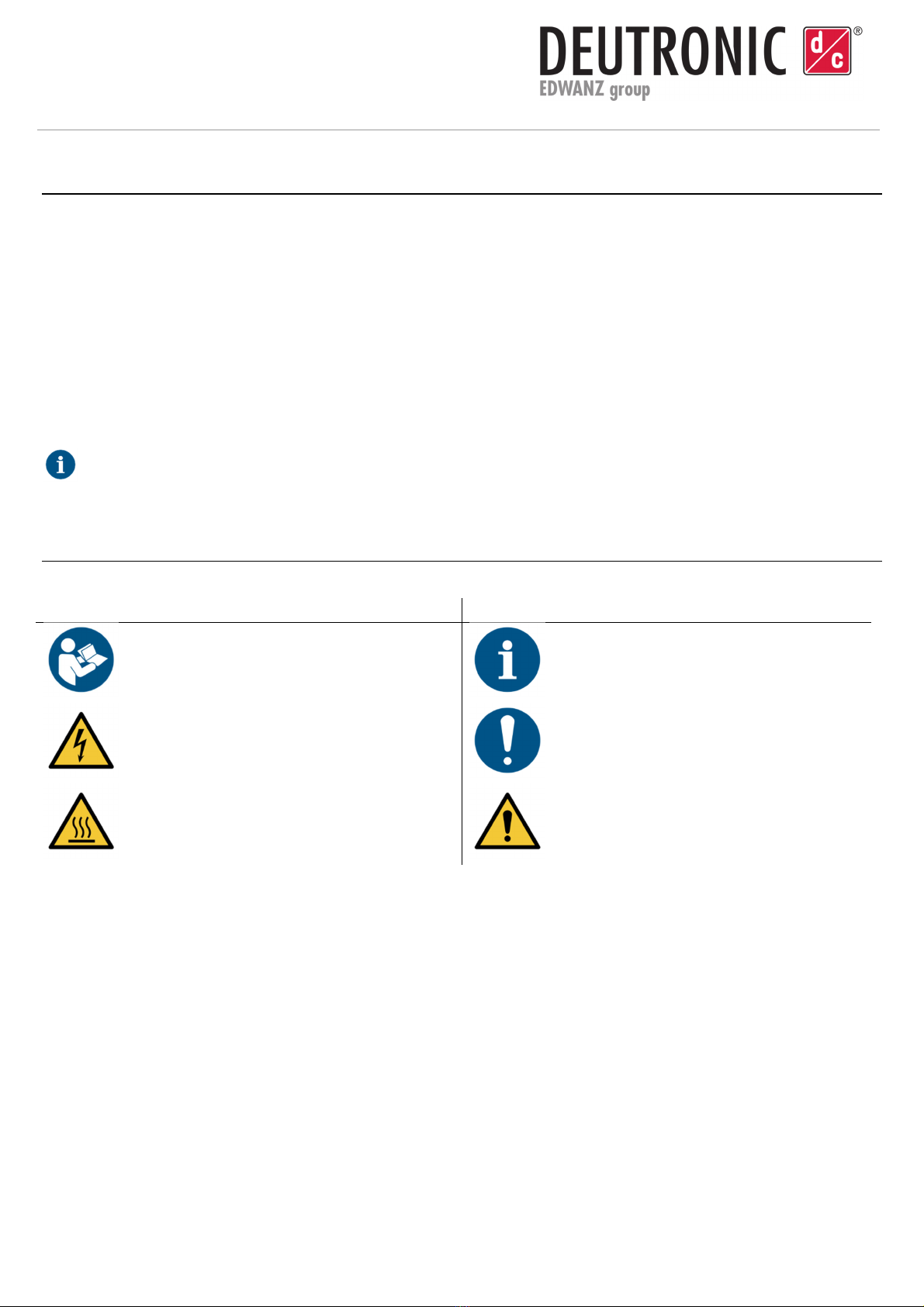
2. Symbols
The used safety and warning symbols have the following meaning:
D
EVICE
L
ABEL
D
EVICE AND DOCUMENTATION LABEL
Read the operation manual
Information
Warning of electrical voltage
Note
Warning of hot surface
General warning signal

Deutronicstr. 5, D - 84166 Adlkofen
Tel.: +49 (0) 8707 920-0
Fax: +49 (0) 8707 1004
http://www.deutronic.com
Installation and safety instructions – DVC/DVCH/DR Version: 12.07.2022 Page 3 of 8
3. Intended Use
The intended use results from the listed standards in the data sheet.
Additional certifications might be necessary (e.g. E1 approval). Contact Deutronic Elektronik GmbH for specific
applications.
The device may only be installed and operated by qualified and instructed personnel.
A DC/DC converter converts DC voltage applied at the input into DC voltage with higher, lower or inverted voltage level.
The conversion is carried out by a periodically working electronic switch and one or more energy storages devices. The
DC/DC converters by Deutronic Elektronik GmbH are equipped with internal EMC filters to guarantee EMC conformity
according to basic industry standards. Nevertheless, additional measures may be necessary during the installation,
considering also the field of application and ambient conditions, to ensure EMC conformity with the applicable product
standards.
For the respective application, it is essential to consider whether a galvanic isolation is required between the inpu
t
and output circuits.
The DC/DC converter must be selected accordingly.
4. Warranty
Deutronic Elektronik GmbH wants to point out that all warranty claims expire, if:
•the device was opened and/or the seal is damaged.
•the device was changed mechanically or electrically.
•the device was operated under non-intended use
•prohibitions and instructions of this manual were violated.
•accessories not approved by Deutronic Elektronik GmbH were used
5. Unpacking
5.1 Control before the first commissioning
•Check the delivery immediately after receipt for completeness and transport damages such as mechanical
damages to the device housing, cables or accessories.
•If there is damage to the device, this needs to be reported to the transport company immediately.
•If there are damages to the device, to cables or accessory parts detected or suspected, do not proceed with
the installation and commissioning under any circumstances.
•In this case, label the device as defective.
•After a hard hit or fall damage, the device should not be used anymore.

Deutronicstr. 5, D - 84166 Adlkofen
Tel.: +49 (0) 8707 920-0
Fax: +49 (0) 8707 1004
http://www.deutronic.com
Installation and safety instructions – DVC/DVCH/DR Version: 12.07.2022 Page 4 of 8
5.2 Disposal of the packaging material
•Keep used packaging material for a possible reuse.
•If this is not possible, ensure an appropriate and environmentally friendly disposal of the packaging material
while considering the current environment protection guidelines.
5.3 Storage
•Incorrect or improper storage may result in damage to the device.
•Protect the device during storage against pollution, humidity and extreme temperatures.
•After long storage times, check the proper function of the device before use.
6. Installation
6.1 Requirements for the installation place
•The device may only be operated in the environmental conditions specified in the data sheet.
•The operation of the device may only take place on a mechanical, stable, level and not burnable surface. .
•Make sure that there is sufficient cooling according to the application, see chapter 6.3.
•It has to be ensured that no metallic items can fall between the input terminals, the output terminals of the
converter and lines connected to them. There is danger of short circuit and fire.
•The device may not be operated in close proximity of aggressive vapors, in explosion-endangered areas or in
proximity of ignition sources.
6.2 Operating situation
•The operation of the device is only allowed in the operating situations described in the data sheet.
•The user assumes the sole responsibility for the professional execution and safety of the installation.
•Installation sets that are suitable for the installation and approved by Deutronic can be found under
www.deutronic.com.
•Only use installation sets approved by Deutronic.
•The device is to be screwed to the mounting surface at all designated points.
•Include valid standard works, such as VDI 2230 for the calculation of bolted connections.
•It is prohibited to make mechanical changes to the device, such as drilling holes,
for the mounting of additional
installation points.
•Each change to the device may lead to life-threatening operating situations or fire.

Deutronicstr. 5, D - 84166 Adlkofen
Tel.: +49 (0) 8707 920-0
Fax: +49 (0) 8707 1004
http://www.deutronic.com
Installation and safety instructions – DVC/DVCH/DR Version: 12.07.2022 Page 5 of 8
6.3 Cooling
•The cooling concept of the device is exclusively based on heat dissipation via contact cooling between the
device and installation surface.
•The system integrator bears the sole responsibility for a professional installation in the end application and the
control of sufficient heat dissipation from the device to the installation surface.
•To check the temperature development of the device, a reference measurement point is defined in the data
sheet.
•An excess of the maximum permissible temperature can lead to a power reduction of the device or even to a
protective shut-down.
•The use of low amounts of heat-conducting paste is recommended.
•A permanently good thermal connection must be ensured between the contact cooling surface of the device
and the installation surface.
•Avoid material with high thermal resistance such as stickers, varnish layers, pollutions between the contact
cooling surface and installation surface.
•Consider the maximum power loss of the device at the operating points when dimensioning the cooling
concept.
•The possible thermally induced operating states (power reduction, protective shutdown) must be considered
for the overall system.
•DVC(H)x3 with communication interface determine the internal temperature of the device at a specified
measuring point, which is not accessible from the outside. This temperature point refers to the temperature
thresholds for warnings and error states, which can be evaluated via CAN.
7. Installation and preparation for the operation
7.1 Connection
Device connection
•The type plate includes the valid connection dates.
•The maximum output current and maximum output power of the connected users may not exceed the nominal
values of the DC/DC converter.
•Only use accessory parts approved by Deutronic Elektronik GmbH.
•Tighten the connection clamps according to the torque specifications in the data sheet and secure them
against loosening.
•Before starting the installation and maintenance works, separate the system from all energy sources. Secure
against reconnection and ensure that no voltage is present. There is danger of electric shock.
•Do not wear any jewelry or metallic items during commissioning and maintenance works. There is danger of
severe burns because of short circuits.
•No single wires of braids may stick out. Braids must always be completely in the clamps. There is danger of
short circuits and burns.
•Loose fit of DC input and DC output connections may lead to spark formation or overheating. There is danger
of burns.

Deutronicstr. 5, D - 84166 Adlkofen
Tel.: +49 (0) 8707 920-0
Fax: +49 (0) 8707 1004
http://www.deutronic.com
Installation and safety instructions – DVC/DVCH/DR Version: 12.07.2022 Page 6 of 8
Protection
•Generally, the device does not have an input or output protection.
•The primary and secondary side protection of the DC/DC converter in the respective application is the
responsibility of the system integrator.
•Depending on the model, a fuse must be installed according to the data sheet.
Reverse polarity protection
•Generally, the device does not have an integrated electronical reverse polarity protection.
•Devices with connector connection technology may have mechanical reverse polarity protection on the device
side.
•When connecting the device, observe the correct polarity of the connection cables.
•Input and output may not be connected in reverse polarity. Danger of irreparable damages and fire.
Inrush current limitation
•Generally, the device does not have an integrated inrush current limitation.
•If required, intend an external inrush current limitation. The calculation of an external inrush current limitation
mainly depends on the input capacity of the device and the impedance of the used connection cables.
7.2 Cable routing
Cable routing
•All cables connected to the device must not contact the device housing to avoid damages caused by hot
surfaces.
•Lay the cables as freely as possible for a better cooling, however, pay attention to a sufficient fixation.
•Replace damaged cables and lines immediately. The device has to be decommissioned and protected agai
nst
being switched on again.
•Use empty conduits and feedthroughs if cables need to be led through sheet metals or other sharp-edged
parts to avoid mechanic damages.
•Lay all cables so that no damage or mechanical stress occurs. Never bend cables sharply.
•Only use copper cables for the connections of the device.
•If cables are damaged, danger of fire as well as electrical shock exists.
Thermal overheating of the cable isolation may be caused by:
oHot surfaces of the device
oWinding or bundling of input and/or output cables
oJoint routing of the input and output cables of the DC/DC converter.

Deutronicstr. 5, D - 84166 Adlkofen
Tel.: +49 (0) 8707 920-0
Fax: +49 (0) 8707 1004
http://www.deutronic.com
Installation and safety instructions – DVC/DVCH/DR Version: 12.07.2022 Page 7 of 8
Cable dimensioning
•Observe the relevant norms for the cable dimensioning such as VDE 0298-4:2013-06.
•Select the nominal cross section of each conductor so that its current load is not smaller than the maximum
permanent current that flows through the conductor under normal conditions.
Additionally, consider possible overcurrent and transients.
•The limit temperatures of insulating covers and sleeves may not be exceeded.
•Consider the resistance against environmental influences and the expected mechanical load in the respective
application.
•If cables are damaged, danger of fire as well as electrical shock exists.
Thermal overheating of the cable isolation may be caused by:
oHot surfaces of the device
oWinding or bundling of input and/or output cables
oJoint routing of the input and output cables of the DC/DC converter.
EMC – approved cable routing
•Due to electromagnetic compatibility (EMC), input and output cables have to be laid with as much distance to
each other as possible. Ideally, cables are routed away from the device on the opposite sides of the housing
without the cables touching the device housing.
•
The DC/DC converter is intended as a component for the installation into a system. The conformity certificates
for the system have to be rendered by the system integrator.
•The output cables of the DC/DC converter need to be laid to the user as closely and parallel as possible due
to electromagnetic compatibility.
•Interface cables (if existing) may only be connected to the device in a shielded version with a shield at both
ends.
•Interface cables must be laid separately from the input and output cables of the device.
7.3 Communication interface
•The device internal interfaces are galvanically separated from the input and output of the DC/DC converter.
•Use interface cables with a shielding at both ends.

Deutronicstr. 5, D - 84166 Adlkofen
Tel.: +49 (0) 8707 920-0
Fax: +49 (0) 8707 1004
http://www.deutronic.com
Installation and safety instructions – DVC/DVCH/DR Version: 12.07.2022 Page 8 of 8
8. General operation instructions
•The device may not be used by children or persons with limited physical, sensory or mental abilities or with
missing experience or knowledge.
•Store the device out of the reach of children or persons with limited
physical, sensory or mental abilities or with
missing experience or knowledge.
•When unplugging the device, always pull the plug and not the cable.
•Before connecting the DC output cables to the device, check the sockets and plug for possible pollutions.
Only
if the device is separated from the supply network, remove pollutions with a dry cloth.
•Check all plugs and cables for moisture before connection. Never connect the device to the supply with wet
hands.
•Separate the device from the supply, if it is not in use anymore.
•Do not touch both connection clamps of the DC output simultaneously if the device is in operation.
•Control the tight fit of the plug connections before each switch on.
•During the operation, the device with its connected cables may disturb active electronical implants (such as
pacemakers) and, thus, endanger persons.
•Smoking and open fire is forbidden during operation.
•Switch off the supply voltage in case of malfunctions or damages immediately.
9. Cleaning
•Cleaning may only be carried out in a voltage free condition and only with a slightly damp cloth without
addition of chemicals.
10. Contact data
Deutronic Elektronik GmbH
Deutronicstrasse 5
D-84166 Adlkofen / Germany
Tel.: +49 (0)8707 / 920-0
Fax: +49 (0)8707 / 1004
E-Mail: sales@deutronic.com
http://www.deutronic.com
DC Nr. 33592
This manual suits for next models
11
Table of contents
Other EDWANZ group Media Converter manuals


