EYC DST01 User manual

Operation-Manual
eYc DST01 Universal Isolation Signal Converter / Splitter
eYc DST01

www.eyc-tech.com
‧‧‧
2
DST01 Universal Isolation Signal Converter / Splitter
DST01 Signal / Meter
Warning Symbol
This document contains notices that you should observe to ensure your own personal safety, as well
as to protect the product and connected equipment. These notices are highlighted in the manual by a
warning triangle and are marked as follows.
The danger symbol indicates that death or severe personal injury may result if proper
precautions are not taken. Do not proceed beyond a warning symbol until the indicated conditions are fully
understood and met.
Preface
Original equipment manufacturer reserves the right to change information available in this document
without notice. The manufacturer is not liable for any damages incurred to equipment/personal during
installation or use of equipment as explained in this document. User must acquire sufficient knowledge &
skills prior to using equipment in the application and follow all the local standards & regulations to meet
safety requirements.

www.eyc-tech.com
‧‧‧
3
DST01 Universal Isolation Signal Converter / Splitter
DST01 Signal / Meter
Table of Contents
1. Introduction ........................................................................................ 4
1.1 Introduction ......................................................................................... 4
1.2 Features ............................................................................................. 4
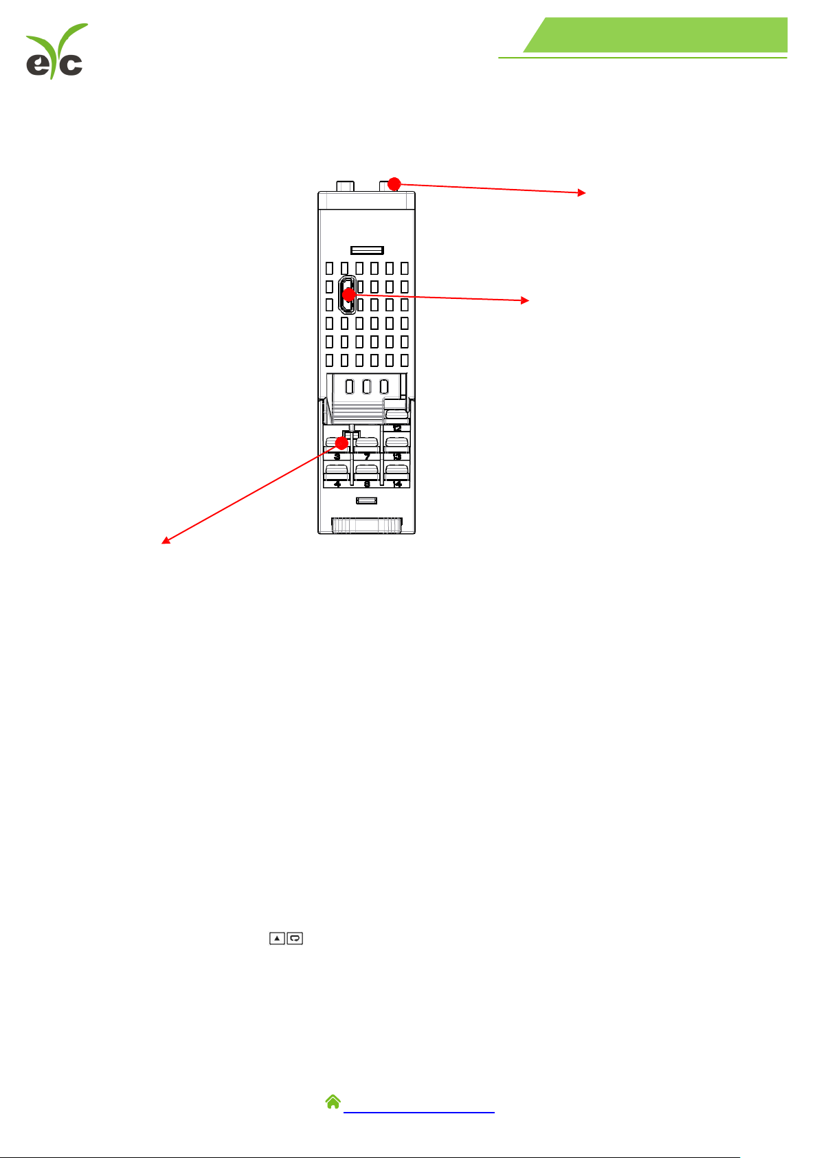
1.3 Programming Port .............................................................................. 5
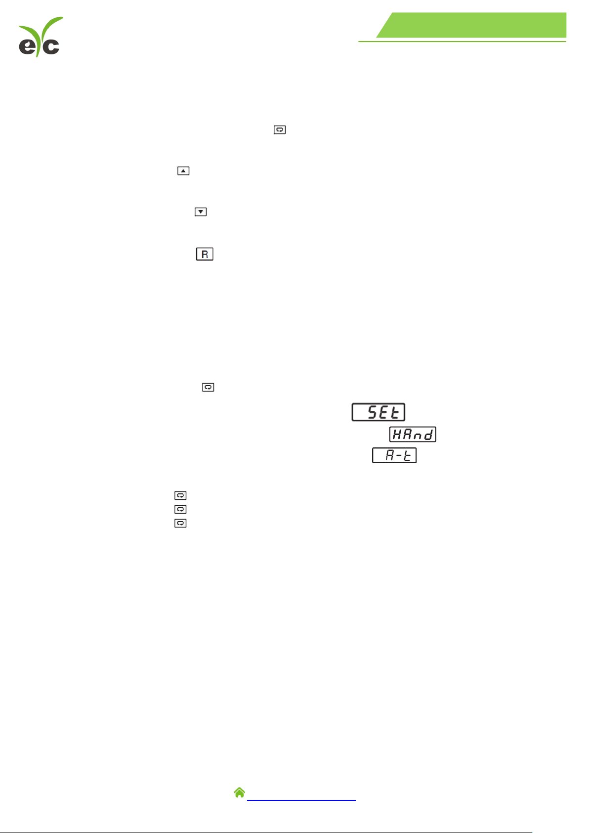
1.4 Display Board Keys ............................................................................ 6
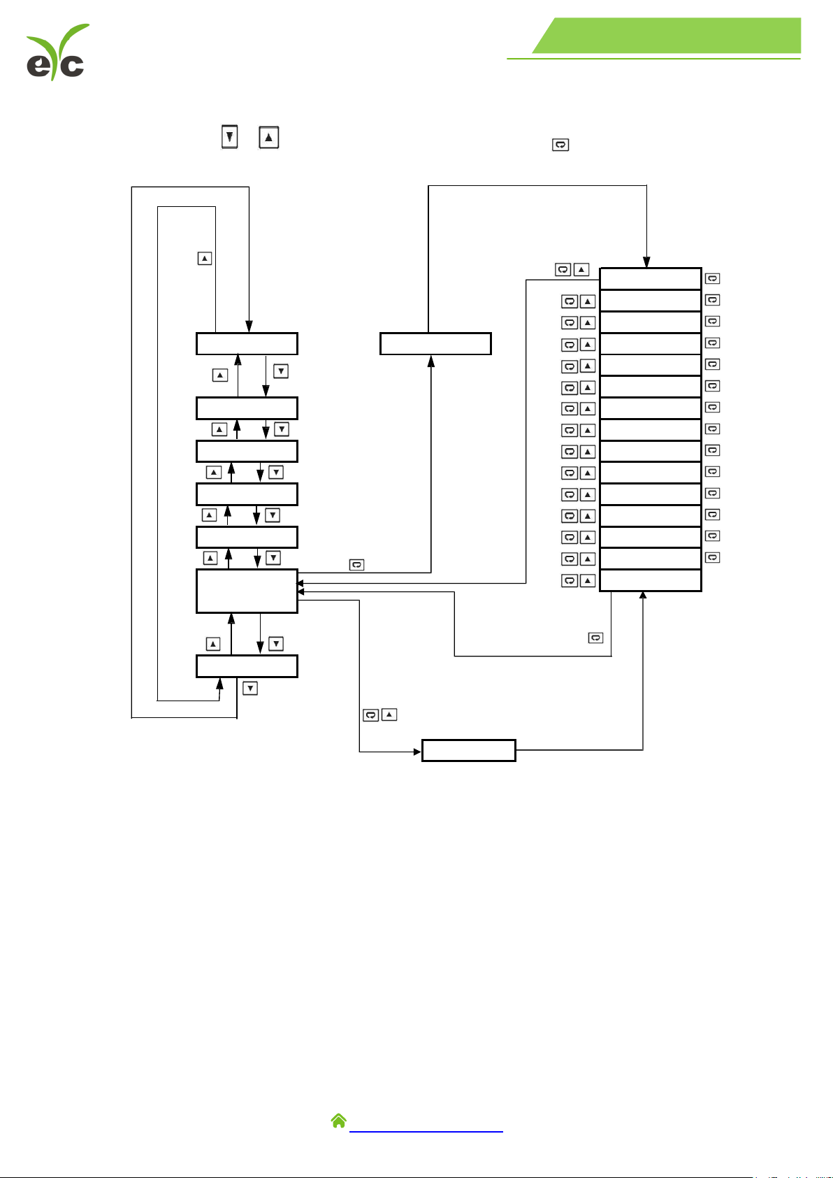
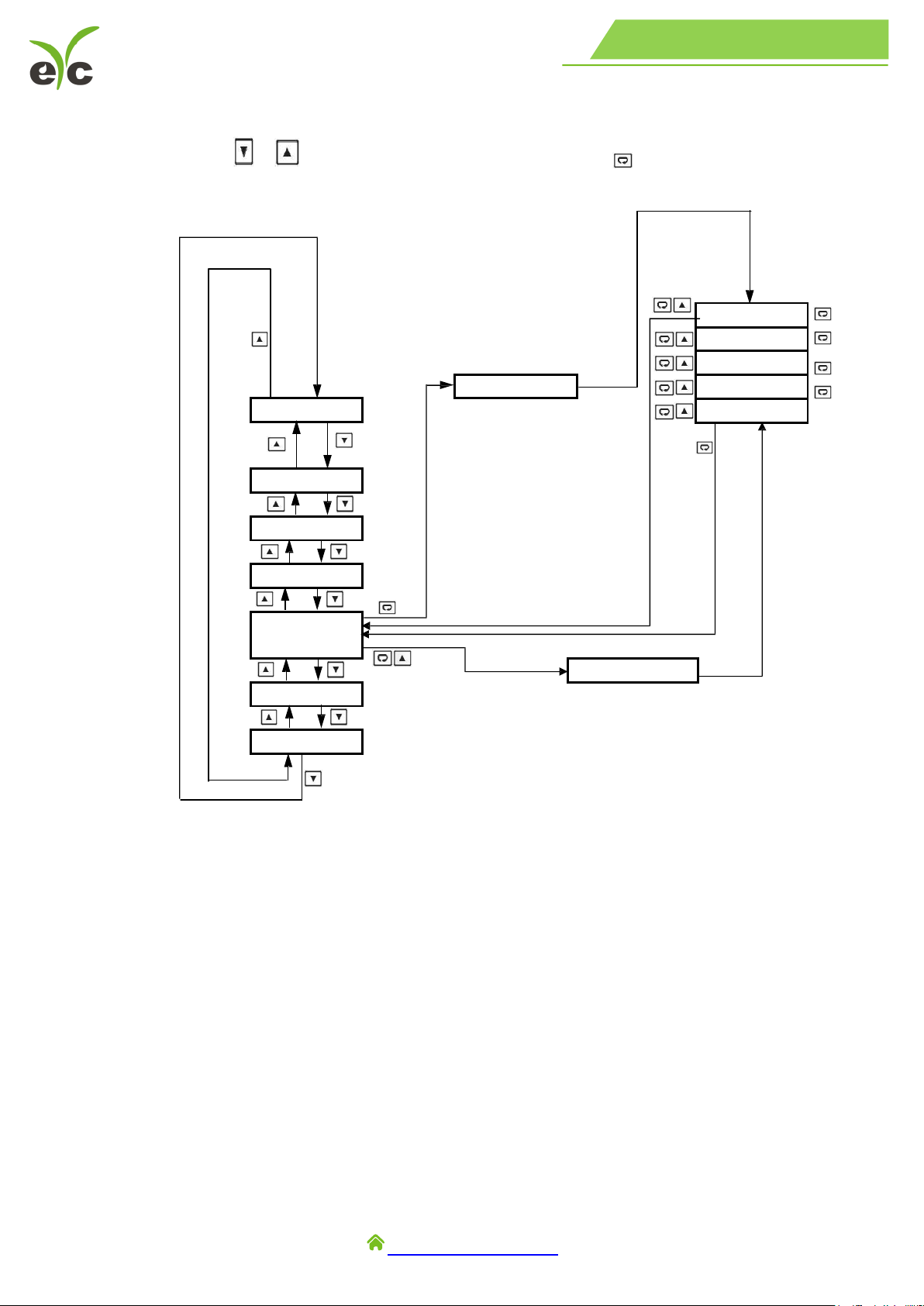
1.5 Menu Flowchart .................................................................................. 8
1.6 Parameter Availability Table ............................................................... 12
2. Installation and Wiring ....................................................................... 15
2.1 Unpacking .......................................................................................... 15
2.2 Dimension .......................................................................................... 16
2.3 Wiring ................................................................................................. 17
3. Programming ...................................................................................... 22
3.1 User Security ...................................................................................... 22
3.2 Calibration Password .......................................................................... 22
3.3 Signal Input ........................................................................................ 22
3.4 Output Type ........................................................................................ 23
3.5 Retransmission ................................................................................... 23
3.6 Zero and Span Adjustment ................................................................. 23
3.7 Square Root Function(SQRT) ............................................................ 23
3.8 User Calibration .................................................................................. 24
3.9 Digital Filter ........................................................................................ 25
3.10 Manual Control ................................................................................... 25
3.11 Factory Default ................................................................................... 25
3.12 Data Communication .......................................................................... 25
3.13 Digital Input ........................................................................................ 26
4. Calibration ........................................................................................... 27
4.1 Equipment Required Before Calibration ............................................. 27
5. Communication .................................................................................. 30
5.1 Functions Supported .......................................................................... 30
5.2 Exception Responses ......................................................................... 31
5.3 Error Code .......................................................................................... 32
5.4 Mode .................................................................................................. 32
5.5 PROG Code ....................................................................................... 32
5.6 Scaling ................................................................................................ 33
5.7 Data Conversion ................................................................................. 33
5.8 Communication Examples .................................................................. 33

www.eyc-tech.com
‧‧‧
4
DST01 Universal Isolation Signal Converter / Splitter
DST01 Signal / Meter
1. Introduction
1.1 Introduction
DST01 The signal conditioner incorporates two bright and easy to read LCD displays which
indicate process value(PV) and user selected parameter.
Powered by a DC 12 ... 38 V or AC 95 ... 250 V supply. It is fully programmable for linear
voltage, linear current, Pt100 and thermocouple types such as J, K, T, E, B, R, S, N, L, U, P, C, and
D input. Its fast sampling rate allows the signal conditioner to retransmit the signal faster, the
maximum of 3 retransmission with one input.
1.2 Features
Signal isolation:Power supply;Analog input
3 groups of analog output
1 set RS-485 output
Multiple input signals
LED display working status
Easy button operation planning
DIN rail installation, high safety & stability

www.eyc-tech.com
‧‧‧
5
DST01 Universal Isolation Signal Converter / Splitter
DST01 Signal / Meter
1.3 Programming Port
A Micro USB programming port is available for automatic configuration, calibration and
firmware upgrades without the need to access the keys on the front panel.
Front Panel
Micro USB Programming Port
Terminals
Lockout Protection
According to user security requirements, one of four lockout levels(NONE, ALL, USER, SET) can
be selected to prevent certain settings from being changed.
Digital Filter
A first-order low-pass filter with a programmable time constant is used to improve the stability of the
process value(PV). This is particularly useful in certain applications where the process value is too
unstable to be read
Event Input
Event Input is available as an option to change certain function.
Analog Retransmission
This signal conditioner can do a maximum of 3 analog retransmission with one input.
Bidirectional Menu Navigation
This controller has bidirectional menu navigation. This will allow the user to access previous menu
settings easily by using keys.
SQRT Function
The signal conditioner is having PV SQRT function

www.eyc-tech.com
‧‧‧
6
DST01 Universal Isolation Signal Converter / Splitter
DST01 Signal / Meter
1.4 Display Board Keys
There are 4 Keys available in the display board for the user to operate as explained
below.
1. SCROLL KEY or ENTER KEY:
This key is used to select a parameter to be viewed or adjusted.
2. UP KEY:
This key is used to increase the value of the selected parameter.
3. DOWN KEY:
This key is used to decrease the value of the selected parameter.
4. RESET KEY:
This key is used to:
1. Revert the display to the home screen.
2. Reset a latching alarm once the alarm condition is removed.
3. Stop manual control mode, auto-tuning mode or calibration mode.
4. Clear an auto-tuning or communication error message.
5. Restart the dwell timer when the dwell timer has timed out.
6. Enter the manual control menu if the failure mode occurs.
ENTER KEY:Press and hold for 5 seconds or longer to:
1. Enter the setup menu. The display will show
2. Enter the manual control mode. The display will show
3. Enter the auto-tuning mode. The display will show
4. Perform calibration of a selected parameter during the calibration procedure
Press and hold for 6.2 seconds, then let go to select manual control mode.
Press and hold for 7.4 seconds, then let go to select auto-tuning mode.
Press and hold for 8.6 seconds, then let go to select calibration mode.
During power-up, the upper display will show PROG and the lower display will show the
Firmware version for 6 seconds.

www.eyc-tech.com
‧‧‧
8
DST01 Universal Isolation Signal Converter / Splitter
DST01 Signal / Meter
1.5 Menu Flowchart
The Menu has been divided into 5 groups. They are as follows:
Basic Menu
Output Menu(oUt)
Communication Menu(CoMM)
Manual Mode Menu(MANU)
Calibration Menu(CALI)
(1) Basic Menu
Use
or
key to get bASE in the lower display then use key to enter
to
Base menu parameters.
INPT
UNIT
dP
INLO
INHI
FILT
dISP
L.CUT
SQRt
dI
oFt.L
CA.Lo
oFt.H
CA.HI
CodE
LoCK
oFS1
oFS2
bASE
FILE
PV,MV
PASS=CODE
CALI
MANU
CoMM
oUt
PASS=CODE

www.eyc-tech.com
‧‧‧
9
DST01 Universal Isolation Signal Converter / Splitter
DST01 Signal / Meter
(2) Output Menu (oUt)
Use
or
key to get oUT in the lower display then use key to enter to output
menu parameters.
PASS=CODE
PASS=CODE
O1TY
ANL1
ANH1
otZ1
otS1
O2TY
ANL2
ANH2
otZ2
otS2
O3TY
ANL3
ANH3
otZ3
otS3
FILE
PV,MV
bASE
CALI
MANU
CoMM
oUt

www.eyc-tech.com
‧‧‧
10
DST01 Universal Isolation Signal Converter / Splitter
DST01 Signal / Meter
PASS=CODE
PASS=CODE
FILE
PV,MV
bASE
CALI
MANU
CoMM
oUt
(3) Communication Menu (CoMM)
Use
or
key to get CoMM in the lower display then use key to enter
into
communication menu parameters.
AddR
bAUd
dAtA
PARI
StoP

www.eyc-tech.com
‧‧‧
12
DST01 Universal Isolation Signal Converter / Splitter
DST01 Signal / Meter
(5) Calibration Mode
Use
or
key to get CALI in the lower display then use key to enter
into
Calibration Mode parameters.
Note:
The flow chart shows a complete list of all parameters. For actual application, the number of
available parameters will vary depending on the setup and will be less than that shown in the
flow chart.
1.6 Parameter Availability Table
Register
Address
Parameter
Notation
Existence Conditions
0
PASS
Exists unconditionally
1
INPT
Exists unconditionally
2
UNIT
Exists unconditionally
3
DP
Exists unconditionally
4
IN.Lo
Exists if INPT selects 4 ... 20, 0 ... 20, 0 ... 50, 0 ... 60,
0 ... 5 V,1 ... 5 V, or 0 ... 10
5
IN.HI
PASS=CODE
KPAS=3418
KPAS=3418
Ad.Lo
Ad.HI
Rtd.L
Rtd.H
CJ.Lo
CJ.HI
V1/L
V1.G
MA1.L
MA1.G
FILE
PV,MV
bASE
CALI
MANU
CoMM
oUt

www.eyc-tech.com
‧‧‧
13
DST01 Universal Isolation Signal Converter / Splitter
DST01 Signal / Meter
Register
Address
Parameter
Notation
Existence Conditions
6
AVG
Exists unconditionally
7
DISP
Exists unconditionally
8
LCUT
Exists unconditionally
9
SQRT
Exists if INPT selects 4 ... 20, 0 ... 20, 0 ... 50, 0 ... 60,
0 ... 5 V,1 ... 5 V, or 0 ... 10
10
DI
Exists if OFS1 selects DI1 or OFS2 selects DI2
11
OFSTL
Exists unconditionally
12
CALO
Exists unconditionally
13
OFSTH
Exists unconditionally
14
CAHI
Exists unconditionally
15
CODE
Exists unconditionally
16
LOCK
Exists unconditionally
17
OUT1
Exists unconditionally
18
ANL1
Exists unconditionally
19
ANH1
Exists unconditionally
20
OTZ1
Exists unconditionally
21
OTS1
Exists unconditionally
22
OUT2
Exists unconditionally
23
ANL2
Exists unconditionally
24
ANH2
Exists unconditionally
25
OTZ2
Exists unconditionally
26
OTS2
Exists unconditionally
27
OUT3
Exists if OFS2 selects RETR
28
ANL3
29
ANH3
30
OTZ3
31
OTS3
32
ADDR
Exists if OFS1 selects RS-485
33
BAUD
34
DATA
35
PARI
36
STOP
37
KPAS
Exists unconditionally
38
ADLO
Exists if KPAS is correct
39
ADHI
40
RTDL
41
RTDH
42
CJLO
43
CJHI
44
V1L
45
V1G
46
MA1L
47
MA1G
48
CJCT
Exists unconditionally

www.eyc-tech.com
‧‧‧
14
DST01 Universal Isolation Signal Converter / Splitter
DST01 Signal / Meter
Register
Address
Parameter
Notation
Existence Conditions
49
CJCL
Exists unconditionally
50
PV
Exists unconditionally
51
MV
Exists unconditionally
52
MV1
Exists if MV selects ON
53
MV2
54
MV3
55
EROR
Exists unconditionally
56
MODE
Exists unconditionally
57
PROG
Exists unconditionally
58
CMND
Exists unconditionally
59
JOB
Exists unconditionally
60
OFS1
Exists unconditionally
61
OFS2
Exists unconditionally

www.eyc-tech.com
‧‧‧
15
DST01 Universal Isolation Signal Converter / Splitter
DST01 Signal / Meter
2. Installation and Wiring
Sometimes dangerous voltages capable of causing death are present in this instrument.
Before doing the installation or any troubleshooting procedures, the power to the equipment
must be switched off and isolated. Units suspected of being faulty must be disconnected and
removed to a properly equipped workshop for testing and repair. Component replacement and
internal adjustments must be made by a qualified maintenance person only.
To minimize the possibility of fire or shock hazards, do not expose this instrument to rain or
excessive moisture.
Do not use this instrument in areas under hazardous conditions such as excessive shock,
vibration, dirt, moisture, corrosive gases or oil. The ambient temperature of the area should not
exceed the maximum rating specified in the specification
Remove stains from this equipment using a soft, dry cloth. Do not use harsh chemicals,
volatile solvents such as thinner or strong detergents to clean the equipment in order to avoid
deformation.
2.1 Unpacking
Upon receipt of the shipment, remove the signal conditioner from the carton and inspect
the unit for shipping damage. If any damage is found, contact your local representative
immediately. Note the model number and serial number for future reference when
corresponding with our service centre. The serial number(S/N) is labelled on the box and the
housing of the controller.
The signal condition ner is designed for indoor use only and is not intended for
use in any
hazardous area. It should be kept away from shock, vibration, and electromagnetic fields(such
as variable frequency drives), motors and transformers. It is intended to operate under the
following environmental conditions.
Environmental Parameter
Specification
Operating Temperature
-10°C ... 50°C
Humidity
0% ... 90%RH(Non-condensing)
Altitude
2000 M Maximum

www.eyc-tech.com
‧‧‧
17
DST01 Universal Isolation Signal Converter / Splitter
DST01 Signal / Meter
2.3 Wiring
Sometimes dangerous voltages capable of causing death are present in this instrument.
Before doing the installation or any troubleshooting procedures, the power to the equipment
must be switched off and isolated. Units suspected of being faulty must be disconnected and
removed to a properly equipped workshop for testing and repair. Component replacement and
internal adjustments must be made by a qualified maintenance person only.
The utmost care must be taken to ensure that the maximum voltage rating specified on the
label is not exceeded.
It is recommended that the supply power of these units be protected by fuses or circuit
breakers rated at the lowest value possible. All units should be installed inside a suitably
grounded metal enclosure to prevent live parts being accessible to human hands and metal
tools. All wiring must conform to appropriate standards of good practice and local codes and
regulations. Wiring must be suitable for the voltage, current, and temperature rating of the
system. The tightening torque on the Screw terminals should not exceed 1 N-m (8.9 Lb-in or
10.2 Kg F-cm). Except Thermocouple Wiring, all other wires used are to be standard copper
conductors with the maximum Gauge not exceeding 18AWG. Before powering on the device,
the equipment ground must be connected with a minimum of 1.6mm diameter conductor for
protective grounding.
(1). Terminal Connection
AC 95 ... 250 V

www.eyc-tech.com
‧‧‧
18
DST01 Universal Isolation Signal Converter / Splitter
DST01 Signal / Meter
(2). Power Wiring
The device is designed to operate at either DC 12 ... 38 V or AC 95 ... 250 V depending on power
input option ordered. Check that the installation voltage corresponds with the power rating
indicated on the product label before connecting power to the controller. Near
the controller, a
fuse and a switch rated at 2 A / AC 250 V should be equipped as shown below.
This equipment is designed for installation in an enclosure which provides adequate
protection against electric shock. The enclosure must be connected to earth ground.
Local requirements regarding electrical installation should be rigidly observed.
Consideration should be given to prevent unauthorized persons from accessing the power
terminals.
(3). Sensor Installation
Proper sensor installation can eliminate many problems in a control system. The probe
should be placed so that it can detect any temperature change with minimal thermal lag. In a
process that requires fairly constant heat output, the probe should be placed close to the heater.
In a process where the heat demand is variable, the probe should be closed to the work area.
Some experiments with probe location are often required to find this optimum position.
In a liquid process, the addition of a stirrer or agitator can help to eliminate thermal lag.
Since the thermocouple is basically a point measuring device, placing more than one
thermocouple in parallel can provide average temperature readout and produce better
results
in most air heated processes.
The proper sensor type is also a very important factor to obtain precise measurements.
The sensor must have the correct temperature range to meet the process requirements. In
special processes, the sensor might need to have different requirements such as being leak-
proof, ant vibration, antiseptic, etc. Standard sensor limits of error are ±4°F (±
2°C) or 0.75%
of sensed temperature (half that for special) plus drift caused by improper
protection or an
over-temperature occurrence. This error is far greater than controller error and cannot be
corrected on the sensor except by proper selection and replacement.
(4). Input Wiring
AC 90 ... 250 V
or
DC 12 ... 38 V
2 A / AC 250 V

www.eyc-tech.com
‧‧‧
20
DST01 Universal Isolation Signal Converter / Splitter
DST01 Signal / Meter
Output 3
Output 3 Linear Current
Output 3 Linear Voltage
(6). Digital Input Wiring
The digital input can accept a switch (dry contact) or an open collector signal.
The digital input function is activated as the switch is closed or an open collector (or a
logic signal) is pulled down. Only one Event input can be used.
11
DI2
12
13
DI1
14
4 ... 20 mA
0 ... 10 V
Table of contents
Other EYC Media Converter manuals
Popular Media Converter manuals by other brands

Prism Sound
Prism Sound ADA-8 Operation manual

Thor Broadcast
Thor Broadcast H-12HDMI-QAM-IPLL user manual

Delta
Delta DA/AU-3 user manual

World Video Sales
World Video Sales MicroImage Video Systems ENC400A Operation manual

TV One
TV One C2-7100 Operation manual

PULSEEIGHT
PULSEEIGHT P8-HDBT-L-SP4 quick start guide