FMUser FUTV4318A User manual

FMUSER INTERNATIONAL GROUP INC. 广州市汉婷生物科技开发有限公司
FUTV4318A 8 in 1 MPEG4 AVC/H.264 HD Encoder
User’s Manual
Date: 2015-04-29
Version: 1.0
NMS Version: 2.2.5
SW: 0.17F
HW: 0.8
FMUSER International Group Inc.

FMUSER INTERNATIONAL GROUP INC. 广州市汉婷生物科技开发有限公司
DIRECTORY
CHAPTER 1 PRODUCT INTRODUCTION................................................................................3
1.1 OUTLINE............................................................................................................................3
1.2 MAIN FEATURES...............................................................................................................3
1.3 SPECIFICATIONS ..............................................................................................................4
1.4 PRINCIPLE CHART............................................................................................................5
1.5 APPEARANCE AND ILLUSTRATION.................................................................................5
CHAPTER 2 INSTALLATION GUIDE........................................................................................7
2.1 ACQUISITION CHECK.......................................................................................................7
2.2 INSTALLATION PREPARATION.........................................................................................7
2.3 WIRE’S CONNECTION.......................................................................................................9
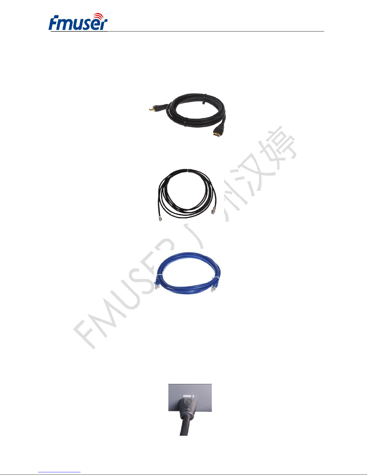
2.4 SIGNAL CABLE CONNECTION.........................................................................................9
CHAPTER 3 OPERATION......................................................................................................12
3.1 INITIALIZING....................................................................................................................12
3.2 GENERAL SETTING........................................................................................................12
CHAPTER 4 SNMP OPERATION...........................................................................................23
4.1 INSTALLATION................................................................................................................23
4.2 SOFTWARE OPERATION................................................................................................23
4.3 FUTV4318A8 IN 1 MPEG-4 AVC/ H.264 HD ENCODER OPERATION.............................28
4.4 OTHER SETTINGS...........................................................................................................38
CHAPTER 5 TROUBLESHOOTING.......................................................................................42
CHAPTER 6 PACKING LIST..................................................................................................43

FMUSER INTERNATIONAL GROUP INC. 广州市汉婷生物科技开发有限公司
3/ 43
Chapter 1 Product Introduction
1.1 Outline
The FMUSER FUTV4318A 8-in-1 MPEG-4 AVC/H.264 HD encoder is our newest
professional HD audio & video encoding and multiplexing device with powerful
functionality. It is equipped with 8 HDMI channels input supporting MPEG-4 AVC/H.264
High Profile code format & main Profile code format and 1 ASI input. It can multiplex
the ASI input TS and the 8 encoded SPTS to generate a MPTS output with the inserted
PSI/SI information. In conclusion, its high integration and cost-effective design make
this device widely used in variety of digital distribution systems such as CATV digital
head-end, satellite and terrestrial digital TV, etc.
1.2 Main Features
lSupport 8 HDMI channels input & 1 ASI Input
lSupport H.264/AVC high profile level 4.0 video encoding
lSupport MPEG1 Layer 2 (HE-AAC (V2) or LC-AAC optional) audio encoding
lSupport PSI/SI editing and inserting
lSupport VBR or CBR video bitrate mode
lSupport 720P, 1080I, 1080P HD video format
lSupport ASI output MPTS or 8 SPTS
lSupport IP Output MPTS and 8 SPTS
lSupport IP null packet filter
lSupport PID filter and transparent transport
lReal-time output bit-rate monitoring
lUpdate device through NMS port
lSupport LCD / keyboard operating, and network management (SNMP)

FMUSER INTERNATIONAL GROUP INC. 广州市汉婷生物科技开发有限公司
4/ 43
1.3 Specifications
Input 8 HDMI inputs
1ASI input, BNC interface
Video
Resolution
1920×1080_60P, 1920×1080_50P
1920×1080_60i, 1920×1080_50i
1280×720_60P, 1280×720 _50P
720x576_50i, 720x480_59.95i
Encoding MPEG-4AVC/H.264 high profile level 4.0
Bit-rate 0.8Mbps~19Mbps (each channel)
Rate Control CBR/VBR
GOP Structure IBBP
Advanced
Pretreatment De-interlacing, Noise Reduction, Sharpening
Audio
Encoding MPEG-1 Layer II, HE-AAC (V2), LC-AAC
Sampling rate 48KHz
Resolution 24 bit
Bit-rate 64Kbps~384Kbps each channel
Multiplexing 1ASI input multiplexed with local 8 channels of TS
Stream output
2*ASI output, BNC interface
MPTS and 8 SPTS over UDP, 1000 Base-T
Ethernet interface (UDP unicast / multicast)
System function LCD/keyboard operating, NMS supporting
Chinese-English control interface
Ethernet software & hardware upgrade
Miscellaneous
Dimension (W× L× H) 440mm×410mm×44.5mm
Approx weight 4kg
Temperature 0~45℃(work), -20~80℃(Storage)
Power AC 100V-220V±10%, 50/60Hz
Consumption 25W

FMUSER INTERNATIONAL GROUP INC. 广州市汉婷生物科技开发有限公司
5/ 43
1.4 Principle Chart
1.5 Appearance and Illustration
Front Panel Illustration:
Indicate area: All indicators will light on when the device is on the current working state.
1 LCD Screen
2 Indicators
Power Indicator
TS In: Input Lock Indicator
CH1-CH8: When the program has been multiplexed,
the indicator will be on.
3 UP/ DOWN, LEFT/RIGHT Keys
4 Enter Key
5 Menu Key
6 Lock Key

FMUSER INTERNATIONAL GROUP INC. 广州市汉婷生物科技开发有限公司
6/ 43
Rear Panel Illustration:
1 8 * HDMI Input Ports
2 ASI Input Port
3 2 * ASI Output Ports
4 Data Port (for IP Signal Output)
5 NMS (Network Management Port)
6 Power Switch and socket
7 Grounding Pole

FMUSER INTERNATIONAL GROUP INC. 广州市汉婷生物科技开发有限公司
7/ 43
Chapter 2 Installation Guide
2.1 Acquisition Check
When users open the package of the device, it is necessary to check items according to
packing list. Normally it should include the following items:
ØFUTV4318A 8 in 1 MPEG-4 AVC/H.264 HD Encoder
ØUser’s Manual
ØHDMI Cable
ØASI Cable
ØPower Cord
If any item is missing or mismatching with the list above, please contact local dealer.
2.2 Installation Preparation
When users install device, please follow the below steps. The details of installation will be
described at the rest part of this chapter. Users can also refer rear panel chart during the
installation.
The main content of this chapter including:
ØChecking the possible device missing or damage during the transportation
ØPreparing relevant environment for installation
ØInstalling Encoder
ØConnecting signal cables
ØConnecting communication port (if it is necessary)
2.2.1 Device’s Installation Flow Chart is Illustrated as following:

FMUSER INTERNATIONAL GROUP INC. 广州市汉婷生物科技开发有限公司
8/ 43
2.2.2 Environment Requirement
Item Requirement
Machine Hall
Space
When user installs machine frame array in one
machine hall, the distance between 2 rows of machine
frames should be 1.2~1.5m and the distance against wall
should be no less than 0.8m.
Machine Hall
Floor
Electric Isolation, Dust Free
Volume resistivity of ground anti-static material:
1X10⁷~1X10¹⁰Ω,Grounding current limiting resistance: 1M
(Floor bearing should be greater than 450Kg/㎡)
Environment
Temperature 5~40℃(sustainable ),0~45℃(short time),
installing air-conditioning is recommended
Relative
Temperature 20%~80% sustainable 10%~90% short time
Pressure 86~105KPa
Door &
Window Installing rubber strip for sealing door-gaps and dual
level glasses for window
Wall It can be covered with wallpaper, or brightness less
paint.
Fire Protection
Fire alarm system and extinguisher
Power
Requiring device power, air-conditioning power and
lighting power are independent to each other. Device
power requires AC power 220V 50Hz. Please carefully
check before running.
2.2.3 Grounding Requirement
ØAll function modules’ good grounding designs are the basis of reliability and stability of
devices. Also, they are the most important guarantee of lightning arresting and
interference rejection. Therefore, the system must follow this rule.
ØCoaxial cable’s outer conductor and isolation layer should keep proper electric
conducting with the metal housing of device.
ØGrounding conductor must adopt copper conductor in order to reduce high frequency
impedance, and the grounding wire must be as thick and short as possible.

FMUSER INTERNATIONAL GROUP INC. 广州市汉婷生物科技开发有限公司
9/ 43
ØUsers should make sure the 2 ends of grounding wire well electric conducted and be
antirust.
ØIt is prohibited to use any other device as part of grounding electric circuit
ØThe area of the conduction between grounding wire and device’s frame should be no
less than 25mm2.
2.2.4 Frame Grounding
All the machine frames should be connected with protective copper strip. The grounding
wire should be as short as possible and avoid circling. The area of the conduction between
grounding wire and grounding strip should be no less than 25mm2.
2.2.5 Device Grounding
Connecting the device’s grounding rod to frame’s grounding pole with copper wire.
2.3 Wire’s Connection
The grounding wire conductive screw is located at the right end of rear panel, and the
power switch, fuse, power supply socket is just beside ,whose order goes like this, power
switch is on the left ,power supply socket is on the right and the fuse is just between them.
ØConnecting Power Cord
User can insert one end into power supply socket, while insert the other end to AC
power.
ØConnecting Grounding Wire
When the device solely connects to protective ground, it should adopt independent way,
say, share the same ground with other devices. When the device adopts united way,
the grounding resistance should be smaller than 1Ω.
FCaution:
Before connecting power cord to FUTV4318A 8 in 1 MPEG-4 AVC/H.264 HD Encoder,
user should set the power switch to “OFF”.
2.4 Signal Cable Connection

FMUSER INTERNATIONAL GROUP INC. 广州市汉婷生物科技开发有限公司
10 / 43
The signal connections include the connection of input signal cable and the connection of
output signal cable. The details are as follows:
2.4.1 HDMI input cable illustration:
2.4.2 ASI output cable illustration:
2.4.3 Network Cable illustration (CAT5):
2.4.4 HDMI input interface connection
User can firstly find the HDMI interface on the device according to the connector mark
described on the rear panel illustration, and then connect the HDMI cable (in the
accessories). One end is connected to the head-end equipment while the other end to the
encoder’s HDMI input port. The encoder’s HDMI input port (HDMI1…HDMI8) and its
connection are illustrated as follows:

FMUSER INTERNATIONAL GROUP INC. 广州市汉婷生物科技开发有限公司
11 / 43
2.4.5 ASI output interface connection
User can firstly find the ASI output interface on the device according to the connector mark
described on the rear panel illustration, and then connect theASI cable (in the accessories).
One end is connected to the encoder’s ASI out connector (ASI1, ASI2) while the other end
to the TS stream multiplexer or modulator’s ASI input port. The encoder’s ASI output
interface and its connection are illustrated as follow:
2.4.6 IP Output Interface connection
Users can firstly find the DATA interface on the device according to the connector mark
described on the rear panel illustration, and then connect the network (CAT5). One end of
the network cable is connected to the encoder’s DATA output connector, while the other
end to the TS stream multiplexer IP input port or other device which can input IP signal. The
encoder’s DATA connection is illustrated as follows:
2.4.7 NMS Connection
Users can firstly find the NMS interface on the device according to the connector mark
described on the rear panel illustration, and then connect the network (CAT5). One end of
the network cable is connected to the encoder’s NMS connecter, while the other end to the
computer or the PC. The encoder’s NMS connection is illustrated as follows:

FMUSER INTERNATIONAL GROUP INC. 广州市汉婷生物科技开发有限公司
12 / 43
Chapter 3 Operation
FUTV4318A 8 in 1 MPEG-4 AVC/H.264 HD Encoder’s front panel is user operating
interface. Before operating, user can decide whether directly use the default setting or
customize the input and output parameters setting. The detail operations go as follows:
Keyboard Function Description:
ENTER: Activating the parameters which need modifications, or confirming the change
after modification.
MENU: To cancel presently entered value, resume previous setting and return to previous
menu.
LEFT/RIGHT: To move the “►” to choose or set the parameters.
UP/DOWN: To modify activated parameter or page up/down when parameter is
inactivated.
LOCK: To Lock the screen / cancel the lock state. After pressing lock key, the system will
question the users to save present setting or not. If not, the LCD will display the current
configuration state.
At the “Factory Configuration” page, user can press “ENTER” key to restore the factory
default configuration.
3.1 Initializing
After powering on the device,it will take a few seconds to initialize the system, and then the
LCD will show the device name and output real-time bit-rate in the first row, while the 8
channels’respective input video resolution, frame rate and real-time encoding bit-rate in the
second row in turn. It shows as below:
3.2 General Setting

FMUSER INTERNATIONAL GROUP INC. 广州市汉婷生物科技开发有限公司
13 / 43
By pressing LOCK key, users can enter in the main menu and set the input and output
parameters in the following editing interfaces, the LCD will display the following pages:
The option with “►” is the current selection, users can press the ENTER key to enter the
specified submenu to modify the device parameter.
3.2.1 Input Setting
Under this menu, users can enter the corresponding encoding channel to set the relevant
audio and video input parameters, and select programs to multiplex. The LCD will display 8
submenus which from Encoding Channel 1 to Encoding Channel 8. The setting principle is
the same for Encoding Channel 1-8, so here this manual just takes one channel as the
example to explain. After pressing the enter key, the LCD will display the following pages:
After users enter the submenu, the interface will turn into the following pages, and then
users can enter the corresponding interface to modify the parameters.
3.2.1.1 Video Setting

FMUSER INTERNATIONAL GROUP INC. 广州市汉婷生物科技开发有限公司
14 / 43
ØBitrate
By press “Enter” key, user can modify relevant parameter of encoding rate (adjustable
range: 0.8M~19M), the specific steps are displayed as follows:
ØBitrate Mode
User can choose CBR & VBR at this menu. CBR (Constant Bit-rate) means that the bit-rate
will be a constant value. VBR (Variable Bit-rate) means that the bit-rate will always change
along with the video scene changing.
ØProfile
User can select the configuration of H.264 profile at this menu. There are H.264 High
Profile code format and main Profile code format.
ØLevel
User can select the H.264 level at this menu. The option with bracket is the current choice.
1.1.1.1 Bitrate
8.000Mbps
1.1.1.2 BitrateMod 01/01
[CBR] VBR
1.1.1.3 Profile 01/01
[HIGH] MAIN
1.1.1.4 Level 01/03
[1.2] 1.3 2.0 2.1
1.1.1.4 Level 02/03
[2.2] 3.0 3.1 3.2

FMUSER INTERNATIONAL GROUP INC. 广州市汉婷生物科技开发有限公司
15 / 43
3.2.1.2 Audio Setting
ØAudio Bit Rate Setting
User can set the input audio bit-rate by pressing the enter key to enter the main editing
interface. And there are: 64Kbps, 96Kbps, 112Kbps, 128Kbps, 160Kbps, 192Kbps,
224Kbps, 256 Kbps, 320Kbps, and 384Kbps. After the modification, users can press enter
key again to take the modification into effect. The LCD will display the following pages:
ØAudio Format Setting
AAC: Advanced Audio Coding
Users can set the input audio format in this interface, and the 3 options are MPEG1 Layer
Ⅱ, LC-AAC, and HE-AAC. When users enter the main editing menu, the LCD will display
the following page:
1.1.2.1 Bit Rate 1.1.2.2 Format
1.1.1.4 Level 03/03
[4.0] 4.1 4.2

FMUSER INTERNATIONAL GROUP INC. 广州市汉婷生物科技开发有限公司
16 / 43
3.2.1.3 System Settings
Under this interface, users can set the corresponding system parameters, after the
modification, users can press enter key to take the modification into effect.
ØProgram Number Setting
Users can set the program number by pressing ENTER to enter this submenu. The LCD
will display as below:
ØVideo/Audio/PMT/PCR PID Settings
Users can set these parameters by pressing ENTER to enter these submenus. The LCD
will display the following pages, and the maximum PID number cannot exceed 0x1fff.
►1.1.3.1 Prog Number 1.1.3.2 Video PID
1.1.3.3 Audio PID 1.1.3.4 PMT PID
►1.1.3.5 PCR PID 1.1.3.6 IP Enable
1.1.3.7 Out Address 1.1.3.8 Out Port
►1.1.3.9 Null PKT
1.1.3.1 Program Number
0x0101

FMUSER INTERNATIONAL GROUP INC. 广州市汉婷生物科技开发有限公司
17 / 43
ØIP Enable
ØOut Address/Out Port Setting
User can modify the out address and out port in below interfaces.
ØNull Packet
Users can choose YES (filter the null packet) or NO (don’t filter null packet) to decide
whether to filter the null packet or not.
3.2.1.4 Program Mux Setting
Users can decide whether to open the multiplexing function of the device.
ØChannel Mux
Under this interface, users can decide whether to multiplex the channel encoding stream.
YES means that the device multiplexes the encoding stream into the MPTS, while NO means
that the output program is SPTS. The LCD will display the following pages after pressing
1.1.3.6 IP Enable 01/01
YES [NO]
1.1.3.7 Out Address
224.002.002.002
1.1.3.8 Out Port
1002
1.1.3.9 Null Packet 01/01
YES [NO]

FMUSER INTERNATIONAL GROUP INC. 广州市汉婷生物科技开发有限公司
18 / 43
enter key.
3.2.2 ASI Setting
Users can check the ASI input program amount in this interface, and the LCD will display
the following page. Prog: 006 represents the input program is 6 and Out:003 represents 3
of the 6 programs have been multiplexed.
3.2.3 Output Setting
By press the enter key in the main editing interface, use can set the device output
parameter. The device will display the following page after users pressing the enter key.
3.2.3.1 IP Out Enable
This is the new function of this encoder, user can decide whether to open the IP output
function by press the ENTER key in this menu, and the operating interface will show the
following page:
2.1 Parse ASI Prog Prog: 006 Out: 003
►001 HK1 √002 HK2 X
►3.1 IP Out Enable 3.2 IP Out Address
3.3 IP Out Port 3.4 Trans Stream ID
►3.5 Output Stream 3.6 ASI Output
3.7 UTC Time Config 3.8 Null PKT
►3.9 TS Package Num

FMUSER INTERNATIONAL GROUP INC. 广州市汉婷生物科技开发有限公司
19 / 43
3.2.3.2 IP Out Address
If users enable the IP output function, then users can set the device IP output address in
this interface. After users press the ENTER key, the operating interface will display the
following page:
3.2.3.3 IP Out Port
In this menu, users can set the encoder IP output port number by press the ENTER key to
enter the main editing interface.
3.2.3.4 Trans Stream ID
Users can set the device TS ID in this interface after pressing the ENTER key to enter the
main editing page.
3.2.3.5 Output Stream
Users can modify the bit rate of output stream in this interface after pressing the ENTER
key to enter the main editing page.
3.2.3.6 ASI Output
3.5 Output Stream
040.000 Mbps

FMUSER INTERNATIONAL GROUP INC. 广州市汉婷生物科技开发有限公司
20 / 43
Users can set theASI output in this interface under this menu, and there are 9 options:
MPTS, Channel 1-8.
3.2.3.7 UTC Time
UTC refers to Universal Time Coordinated. User can enter this menu to set the time as
needed and it will then generate the TDT table and show in the user’s STB.
3.2.3.8 Null Packet
3.2.3.9 TS Package Num
User can set the amount of TS packages by entering into below interface.
3.2.4 Network Setting
Users can set the network parameters by pressing the enter key, and the LCD will display
the following interfaces.
3.6 ASI Output 01/03
[MPTS] Channel 1 Channel 2 Channel 3
3.7 UTC Time Configuration
2012-01-29 15:45:03
3.8 Null Packet 01/01
YES [NO]
3.9 TS Package Num 01/02
1 2 3 [4]
3.9 TS Package Num 02/02
[5] 6 7
Table of contents
Other FMUser Media Converter manuals
Popular Media Converter manuals by other brands

KAMEHA
KAMEHA KA164 user manual

Hall Research Technologies
Hall Research Technologies CC-101 user manual

ZyCast
ZyCast digi-MOD Series User guide & installation manual

SignaMax
SignaMax 065 Series user guide

HDCVT TECHNOLOGY
HDCVT TECHNOLOGY HDV-BS11A user manual

Panasonic
Panasonic AJUFC1800 - HD STANDARDS CONVERT System reference

Singular Sound
Singular Sound MIDI MAESTRO Quick Start for First Time Use

TR-Electronic
TR-Electronic CES582S-8192/1 EPN DMS 15H7 KRF Assembly instructions

Fluance
Fluance Fi70 instruction manual

Digiop
Digiop Encoder-HD16 Quick setup guide

Boston Acoustics
Boston Acoustics Horizon TRio manual

Velleman
Velleman PI150BN manual