EDWARDS SYSTEMS TECHNOLOGY IRC-3 Programming manual

IRC-3
Maintenance and Troubleshooting Manual
P/N 270245
Revised 21NOV97
firealarmresources.com

DEVELOPED BY Edwards Systems Technology
6411 Parkland Drive
Sarasota, FL 34243
(941) 739-4300
COPYRIGHT NOTICE Copyright © 1997 Edwards Systems Technology, Inc.
This manual and the products it describes are copyrighted by
Edwards Systems Technology, Inc. (EST). You may not reproduce,
translate, transcribe, or transmit any part of this manual without
express, written permission from EST.
This manual contains proprietary information intended for distribution
to authorized persons or companies for the sole purpose of
conducting business with Edwards Systems Technology, Inc. If you
distribute any information contained in this manual to unauthorized
persons, you have violated all distributor agreements and we may
take legal action.
CREDITS This manual was designed and written by the EST Technical
Services - Documentation Department, Sarasota.
firealarmresources.com

Maintenance and Troubleshooting Manual i
Content
IRC-3 Recommended Spare Parts List • 1
Routine Maintenance • 2
Sensor Cleaning • 3
Troubleshooting the ZAS Line • 5
Required Equipment • 5
Normal Operation • 5
Potential Problems • 5
System Logs • 8
firealarmresources.com

ii Maintenance and Troubleshooting Manual
Important information
Limitation of liability
The content of this manual is proprietary in nature and is intended
solely for distribution to authorized persons, companies, distributors
and/or others for the sole purpose of conducting business associated
with Edwards Systems Technology, Inc. The distribution of
information contained within this manual to unauthorized persons shall
constitute a violation of any distributor agreements and may result in
implementation of legal proceedings.
This product has been designed to meet the requirements of NFPA
Standard 72, 1996 Edition; Underwriters Laboratories, Inc., Standard
864, 7th Edition; and Underwriters Laboratories of Canada, Inc.,
Standard ULC S527. Installation in accordance with this manual,
applicable codes, and the instructions of the Authority Having
Jurisdiction is mandatory. EST, Inc. shall not under any circumstances
be liable for any incidental or consequential damages arising from loss
of property or other damages or losses owing to the failure of EST, Inc.
products beyond the cost of repair or replacement of any defective
products. EST, Inc. reserves the right to make product improvements
and change product specifications at any time.
While every precaution has been taken during the preparation of this
manual to ensure the accuracy of its contents, EST assumes no
responsibility for errors or omissions.
FCC warning
This equipment can generate and radiate radio frequency energy. If this
equipment is not installed in accordance with this manual, it may cause
interference to radio communications. This equipment has been tested
and found to comply within the limits for Class A computing devices
pursuant to Subpart B of Part 15 of the FCC Rules. These rules are
designed to provide reasonable protection against such interference
when this equipment is operated in a commercial environment.
Operation of this equipment is likely to cause interference, in which
case the user at his own expense, is required to take whatever measures
may be required to correct the interference.
firealarmresources.com

Maintenance and Troubleshooting Manual iii
Related Documentation
R
NFPA
National Fire Protection Association (NFPA)
1 Batterymarch Park
P.O. Box 9101
Quincy, MA 02269-9101
NFPA 70 National Electric Code
NFPA 72 National Fire Alarm Code
R
UL
Underwriters Laboratories, Inc. (ULI)
333 Pfingsten Road
Northbrook, IL 60062-2096
UL 38 Manually Actuated Signaling Boxes
UL217 Smoke Detectors, Single & Multiple Station
UL 228 Door Closers/Holders for Fire Protective Signaling Systems
UL 268 Smoke Detectors for Fire Protective Signaling Systems
UL 268A Smoke Detectors for Duct Applications
UL 346 Waterflow Indicators for Fire Protective Signaling Systems
UL 464 Audible Signaling Appliances
UL 521 Heat Detectors for Fire Protective Signaling Systems
UL 864 Standard for Control Units for Fire Protective Signaling Systems
UL 1481 Power Supplies for Fire Protective Signaling Systems
UL 1638 Visual Signaling Appliances
UL 1971 Visual Signaling Appliances
R
Underwriters Laboratories of Canada (ULC)
7 Crouse Road
Scarborough, Ontario M1R 3A9
ULC S527 Standard for Control Units for Fire Alarm Systems
ULC S524 Standard for the Installation of Fire Alarm Systems
ULC S536 Standard for the Inspection and Testing of Fire Alarm Systems
ULC S537 Standard for the Verification of Fire Alarm Systems
PLUS... Requirements of state and local building codes.
Requirements of the Authority Having Jurisdiction.
firealarmresources.com

iv Maintenance and Troubleshooting Manual
Document history
Maintenance and Troubleshooting Manual P/N 270245
Revision Status
Revision Date Reason For Change
1.0 September 1995 Initial Release.
1.5 November 1997 Layout and content revisions.
firealarmresources.com

Maintenance and Troubleshooting Manual 1
IRC-3 Recommended Spare Parts List
As a general guideline, 10% or a minimum of one piece of the
following installed equipment should be available as spare:
• Power Supply
• Zone Cards
• Relay Cards
• ZAS Cards
• CM1N
• CM2N
• Amplifier (If no backup installed in system)
• Printer ribbon
• Horn, bell, strobe, and speaker
As a general guideline, 10% or a minimum of three pieces of the
following installed equipment should be available as spare:
• Monitor Modules
• Control Modules
• Heat Detectors
• Ionization Smoke Detectors
• Photoelectronic Smoke Detectors
• Base, Detector
• Duct detector Filter Kits
• Breakglass Replacement for Pull Stations
• Breakglass Replacement for Warden Stations
System batteries should be replaced at intervals recommended by the
battery manufacturer. Stocking of spare batteries is NOT recommended
because of shelf-life limitations.
firealarmresources.com

2 Maintenance and Troubleshooting Manual
Routine Maintenance
Caution: Disconnect power before removing or installing any modules.
Lethal voltages from other systems may be present even with fire alarm
disconnected.
Single and multi-line network hardware has been designed for ease of
maintenance. Repairs are accomplished by removing a suspected bad
module or card and replacing it with a known good module or card.
Field repair of modules should not attempted. Defective modules
should be replaced and defective modules returned to the factory for
service, where the necessary test equipment and software is available.
Routine maintenance should be performed in accordance with the
procedures in NFPA 72 and the Local Authority Having Jurisdiction.
All panels should be checked for proper operation, and the batteries
should be tested under load.
The following suggested routine maintenance should be performed
annually.
Basic Tools:
1. Common screwdriver, 3/16 x 6 inch blade with insulated handle.
2. High input impedance digital multimeter and probes.
3. One each, 15 KΩ, 1/2 watt resistor.
4. One each, 12 inch jumper lead with clips.
5. Panel door key.
Note: Inform all responsible personnel and the central station of system
maintenance.
1. Visually inspect all connections, wiring and shields. Tighten loose
connections and replace missing cover plates and screws.
2. Remove the positive (red) battery lead from the stand-by battery.
The trouble LED will turn ON after a momentary delay. Pressing
the trouble silence switch will turn OFF the buzzer. Reconnect the
battery.
Caution: Batteries can deliver extremely high currents for short
periods. Remove all jewelry to prevent serious burns caused by short
circuiting the battery.
3. Remove the AC source and verify the panel continues to operate
properly.
Battery Test
To test the batteries, using a 12 inch jumper, short across a fire alarm
input zone (type "A"). After 5 minutes the batteries must not be lower
than 24 volts. If the batteries are low they may be defective.
Upon completion of this test, restore AC power and insure that all
trouble and alarm conditions are reset.
firealarmresources.com

Maintenance and Troubleshooting Manual 3
4. By shorting the various zones with a jumper wire, the various visual
alarm indicators may be visually checked for operation; this test will
also electrically test the panel for proper operation.
Upon conclusion of routine and/or preventative maintenance actions,
verify system operation and inform all responsible parties of system
restoration.
Sensor Alert
A "SENSOR ALERT" message is displayed on the CM1N when the
sensitivity of an addressable analog detector has increased to a level
where unwarranted alarms may occur. Inspection and cleaning of the
detector is indicated.
Magnet Testing
Addressable analog sensors are equipped with a reed switch for testing
purposes. To test the sensor, place a magnet near the plastic base
directly across from the Test Socket. This activates the sensor and
generates an alarm response for the sensor's address.
Sensor Cleaning
NFPA 72 states ,"All smoke detectors shall be visually inspected in
place at least semi-annually to identify missing detectors, detectors
with impeded smoke entry, abnormally dirty detectors, and detectors
no longer suitably located because of occupancy or structural changes".
NFPA 72 also states that a test shall be performed annually "to assure
that each smoke detector is operative and produces the intended
response".
The following recommendations have been extracted from field
bulletins published by the manufacturer of 400 and 500 detectors.
400 and 500 Series Photoelectronic Smoke Detectors
Before cleaning, notify the proper authorities that the system is being
tested. Disable the zone or system to prevent undesirable, unwanted
alarms and proceed with testing and/or maintenance.
1. Remove detector cover by inserting a small blade screwdriver into
the slot provided 90° from the test jack receptacle and twisting the
cover clockwise.
2. Lift screen from photo chamber. Vacuum screen and cover before
using clean compressed air to dislodge and remove any remaining
debris. Replace screens if necessary; part number RS24 (photo) and
RS24T (thermal).
3. Vacuum photo chamber and then use compressed air to remove any
remaining debris and blow area clean.
4. Before re-assembly, be sure all parts are clean.
firealarmresources.com

4 Maintenance and Troubleshooting Manual
5. Replace screen by aligning arrow with the field test slot on the base
of the detector. Push screen gently into place; should fit tightly into
place.
6. Replace cover by gently turning cover clockwise until it locks into
place.
7. Test and verify detector operation.
8. When cleaning and testing has been completed, restore the zone or
system, verify proper operation and notify the proper authorities of
system restoration.
400 and 500 Series Ionization Smoke Detectors
Before cleaning, notify the proper authorities that the system is being
tested. Disable the zone or system to prevent undesirable, unwanted
alarms and proceed with testing and/or maintenance.
1. Remove detector cover by depressing the three lock prongs on top
of the cover and rotating the cover counter-clockwise.
2. Carefully remove the screen.
3. Clean screen thoroughly with a soft brush or vacuum. Screens on
the ionization unit may also be rinsed under clean warm water, then
dried thoroughly before re-assembly.
4. Brush or vacuum the inside area of cover, then remove any
remaining residue with cleaned compressed air: Do not apply water
to this area.
5. Vacuum sensing chamber before using cleaned compressed air to
remove remaining residual debris. Do not apply water to this area.
6. Press screen back into cover.
7. Replace detector cover and turn clockwise to lock into place.
8. Test detector and verify limits as per label on back of detector.
9. When cleaning and testing has been completed, restore the zone or
system, verify proper operation, and notify the proper authorities of
system restoration.
Aerosol Testing
Aerosol should not be used for testing; cigarette, wick or pipe smoke
are the only accepted methods. If aerosol testing must be used; it
should be used only as a go-no-go test and under no circumstances be
used to determine or to verify calibrated sensitivity. Canned aerosol is
not recommended since the use of these products may cause the plastic
to break down and deteriorate.
firealarmresources.com

Maintenance and Troubleshooting Manual 5
Troubleshooting the ZAS Line
Required Equipment
The material in this topic applies to ZAS-1S and ZAS-FIB lines only.
For other types of ZAS line, see the IRC-3 Network Controller Option
Cards Installation Manual for the specific device in question. To
completely troubleshoot ZAS-1S and ZAS-FIB lines, the following
equipment is required:
• computer with IRC-3 download program and download cable
• digital multimeter
• decade resistor box
• oscilloscope
Normal Operation
The communication protocol between the ZAS module and the
analog/addressable devices is digital.
24 V
5 V
0 V
ZAS COMMUNICATIONS ANALOG / ADDRESSABLE DEVICE COMMUNICATIONS
[M&T-001.CDR]
Figure 1
Figure 1 shows the normal polling communication sequence between a
ZAS module and a single analog/addressable module. When multiple
devices are connected to the ZAS line, the first half of the waveform
appears the same but the second half of the waveform will jump
around. For troubleshooting purposes, the system MUST be
temporarily programmed to communicate only to a single module or
device.
Potential Problems
There are three basic causes of erratic ZAS line operation:
1. Excessive Wiring Resistance:
Rarely is excessive wiring resistance the sole cause of ZAS line
problems. For any length of cable, the amount of resistance and
capacitance per foot doesn't change and the ZAS circuit capacitance
limits are usually reached before the resistance limits. Referring to
Figure 1, the digital signal operates between 0 and 24 VDC.
Excessive line resistance causes the signal to shrink from a
firealarmresources.com

6 Maintenance and Troubleshooting Manual
maximum of 26.4 VDC to a lower voltage, for example 23 VDC.
The 3.4 volt drop in the wiring is due to wire resistance.
To measure ZAS line voltage drop, use an oscilloscope to measure
the peak voltage at the ZAS module and at each analog/addressable
device. If the voltage difference is greater than 2 VDC, the
resistance in the wire run is excessive. Too much resistance in the
ZAS wire run is typically caused by small wire size or a bad
connection.
If the wire size is too small for the run length, the only remedies are
to replace the wire with a larger size or install additional ZAS
modules, dividing the line into acceptable lengths. Breaks or bad
connections in the ZAS loop wiring can be identified by comparing
the calculated loop resistance value (described earlier) with the
measured loop resistance value. The measured wiring loop
resistance should not be different from the calculated loop resistance
by much more than a few ohms.
2. Excessive Wiring Capacitance:
The second cause of erratic ZAS line operation is too much
capacitance in the ZAS circuit wiring. Capacitance distorts the
digital signal. Compare the waveform in Figure 1 with that of Figure
2. The capacitance causes the distortion shown in Figure 2 (note 1).
As wiring capacitance increases, the square edges of the digital
wave form start to curve. Excessive wiring capacitance causes the
waveform to curve beyond the point where a device can recognize
the waveform and respond when polled.
24 V
5 V
0 V
ZAS COMMUNICATIONS ANALOG / ADDRESSABLE DEVICE COMMUNICATIONS
[M&T-002.CDR]
NOTE 1
NOTE 2
Figure 2
Wiring capacitance also effects the turn on current spike shown as
note 2 in Figure 2. If the turn on current spike is not present in the
digital sequence, there is a high probability the analog/addressable
device's communication will not be understood by the ZAS
communication module.
To determine if excessive capacitance is the cause of ZAS line
problems, write and download into the CM1/2(N) which contains
the problem ZAS card, a short program which communicates with
only one device on the ZAS line. Disabling all but one device on the
ZAS line will not accomplish the required task.
With all devices connected to the ZAS line and the single device
program loaded, use the oscilloscope to verify the observed
waveform on the terminals of the devices is similar in appearance to
firealarmresources.com

Maintenance and Troubleshooting Manual 7
Figure 1 . The Pulses should not be excessively curved, and the
turn-on pulse must be present. If some pulses appear excessively
rounded and/or the start pulse is missing, too much capacitance is
the problem.
Note: Referring to Figure 1, the pulse width for all values below 5
VDC must be at least 70% of the pulse width for values above 5 VDC,
or the waveform is said to be excessively curved.
ZAS line capacitance problems are typically caused by long wire
runs, ground faults on the ZAS line, improper T-taps, or improper
shielding.
The shield must be treated as a third conductor. It must be free of all
ground faults and have continuity throughout. If the wire
capacitance is too large for the run length, the only remedies are to
replace the wire with a cable having a lower capacitance per foot or
install additional ZAS modules, dividing the line into acceptable
lengths.
3. Ground Faults:
Eliminating ground faults on the ZAS line reduces the amount of
capacitance on the ZAS wiring.
Verify the ZAS line is free of ground faults. Remove all field wiring
except the ZAS line under test from all panels which share a
common power supply with the CM1/2(N) containing the ZAS card.
Verify jumper J1 is installed the trouble sense (lower) card of the
power supply and J2 has been removed. If the CM1/2(N) displays
either a GND0 or P 002 then the ZAS line has a ground fault, which
must be corrected.
If the ZAS circuit is wired with improper T-taps (described earlier)
corrective measures include designing the ZAS line properly and re-
pulling the wire, or balancing the line. Balancing the line can help in
some cases but is not a substitute for proper wiring practice. If line
balancing is required, call EST Technical Services for additional
information.
firealarmresources.com

8 Maintenance and Troubleshooting Manual
System Logs
System Firmware Log
Installation Name: ______________________________________________________________
Date Of Installation: ______________________________________________________________
Installing Distributor: ______________________________________________________________
Installation Performed By:_____________________________________________________________
Component Revision Checksum Date Comment
Data Entry
Program Used
N/A
CM1
CM1N
CM1NX
CM2
CM2N
DCPU
FCCD
PCPU
REM
RZB12-6
SAN
ZAS
CCA
CGP
VDU-3
firealarmresources.com

Maintenance and Troubleshooting Manual 9
Fire Alarm System Log
Installation Name: ______________________________________________________________
Date Of Installation: ______________________________________________________________
Installing Distributor: ______________________________________________________________
Inspection & Test Date: ______________________________________________________________
I & T Performed By: ______________________________________________________________
Time &
Date
Recorded
By
Fire Trouble Display
Message
Probable
Cause
Action
Taken
Action Taken By:
Name & Date
firealarmresources.com

10 Maintenance and Troubleshooting Manual
firealarmresources.com
Other manuals for IRC-3
2
Table of contents
Other EDWARDS SYSTEMS TECHNOLOGY Security Sensor manuals
EDWARDS SYSTEMS TECHNOLOGY
EDWARDS SYSTEMS TECHNOLOGY EST3 User manual
EDWARDS SYSTEMS TECHNOLOGY
EDWARDS SYSTEMS TECHNOLOGY IRC-3 User manual

EDWARDS SYSTEMS TECHNOLOGY
EDWARDS SYSTEMS TECHNOLOGY EST3 User manual
EDWARDS SYSTEMS TECHNOLOGY
EDWARDS SYSTEMS TECHNOLOGY CMDN Owner's manual
EDWARDS SYSTEMS TECHNOLOGY
EDWARDS SYSTEMS TECHNOLOGY CRC Product manual

EDWARDS SYSTEMS TECHNOLOGY
EDWARDS SYSTEMS TECHNOLOGY IRC-3 Owner's manual
EDWARDS SYSTEMS TECHNOLOGY
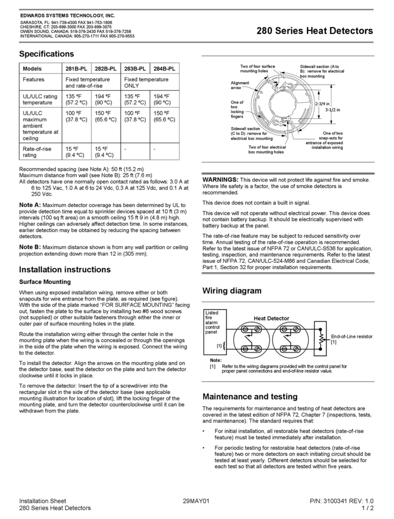
EDWARDS SYSTEMS TECHNOLOGY 280 Series Assembly instructions

EDWARDS SYSTEMS TECHNOLOGY
EDWARDS SYSTEMS TECHNOLOGY EST2 User manual

EDWARDS SYSTEMS TECHNOLOGY
EDWARDS SYSTEMS TECHNOLOGY EST3 User manual

