© 2014 UTC Fire & Security Americas Corporation, Inc. 1 / 4 P/N 270495-EN • REV 06 • ISS 10JUL14
Power Supplies
Installation Sheet
Description
This installation sheet applies to the following models:
•3-PPS/M(-230) Primary Power Supply
•3-BPS/M(-230) Booster Power Supply
•3-BBC/M(-230) Booster/Charger Supply
3-PPS/M(-230) Primary Power Supply
The 3-PPS/M(-230) Primary Power Supply provides the required
power and related supervision functions for the control panel. The
3-PPS/M(-230) comprises a heat sink assembly and a monitor module.
The monitor module plugs into the rail, and the heat sink and the heat
sink assembly mount onto the rail chassis.
The 3-PPS/M(-230) provides filtered, regulated power to the rail
chassis modules as well as 24 VDC for operating ancillary equipment.
AC power and battery connections are made to fixed terminals on the
heat sink assembly, away from the panel’s power-limited wiring.
The 3-PPS/M(-230) provides a dual rate constant current battery
charger circuit with automatic temperature compensation. To prevent
memory problems and total battery discharge, a battery monitor circuit
supervises the standby batteries and disconnects them when they
reach the low battery threshold.
The 3-PPS/M(-230) checks the AC input source and automatically
switches to battery power in the event of a brownout or loss of AC
power. In the event of a failure of one or more booster power supplies,
the 3-PPS/M(-230) determines its ability, along with the surviving
booster supplies, to supply the load. If the load exceeds the ability of
the primary and surviving booster supplies to meet the demand, the
3-PPS/M(-230) automatically switches in the standby batteries. The
3-PPS/M(-230) also switches in the standby batteries if an overload
causes the heat sink temperature to reach a high level.
The power supply monitor module provides the interface between the
3-PPS/M(-230) and the panel, making the required data and power
connections to and from the rail chassis. The monitor module requires
one rail space and is secured to the assembly using snap rivet
fasteners. The monitor module has a hinged front panel for mounting
displays or a blank protective faceplate.
3-BPS/M(-230) Booster Power Supply and 3-BBC/M(-230)
Booster/Charger Supply
The 3-BPS/M(-230) and 3-BBC/M(-230) booster power supplies are
used to provide additional power over and above that of the
3-PPS/M(-230). Each model is composed of a heat sink assembly and
a monitor module. The monitor module plugs into the rail and the heat
sink assembly mounts onto the rail chassis.
Depending on the size of the cabinet, up to three booster power
supplies can be added to make a total of 28 A available for both
internal and external applications. Each booster supply provides
filtered, regulated power to the rail chassis modules as well as 24 VDC
for operating ancillary equipment.
A 3-BPS/M(-230) supply can share a common set of standby batteries
with the 3-PPS/M(-230) or 3-BBC/M(-230). Each 3-BPS/M(-230)
supervises its own battery connection but does not have any battery
charging capability. The 3-BBC/M(-230) is capable of charging standby
batteries.
Each booster supply shares the panel's 24 VDC electrical load with the
3-PPS/M(-230). In the event of a booster power supply failure, a
trouble is annunciated, and the panel load is distributed among the
remaining operational power sources. Should the load ever exceed the
ability of the operable power sources to supply the power, as in the
event of an alarm, the system automatically switches to standby
batteries.
The booster supply monitor module provides the interface between the
booster power supply and the panel, making the required data and
power connections to and from the rail chassis. The monitor module
requires one rail space and is secured to the assembly using snap
rivet fasteners. The monitor module has a hinged front panel for
mounting displays or a blank protective faceplate.
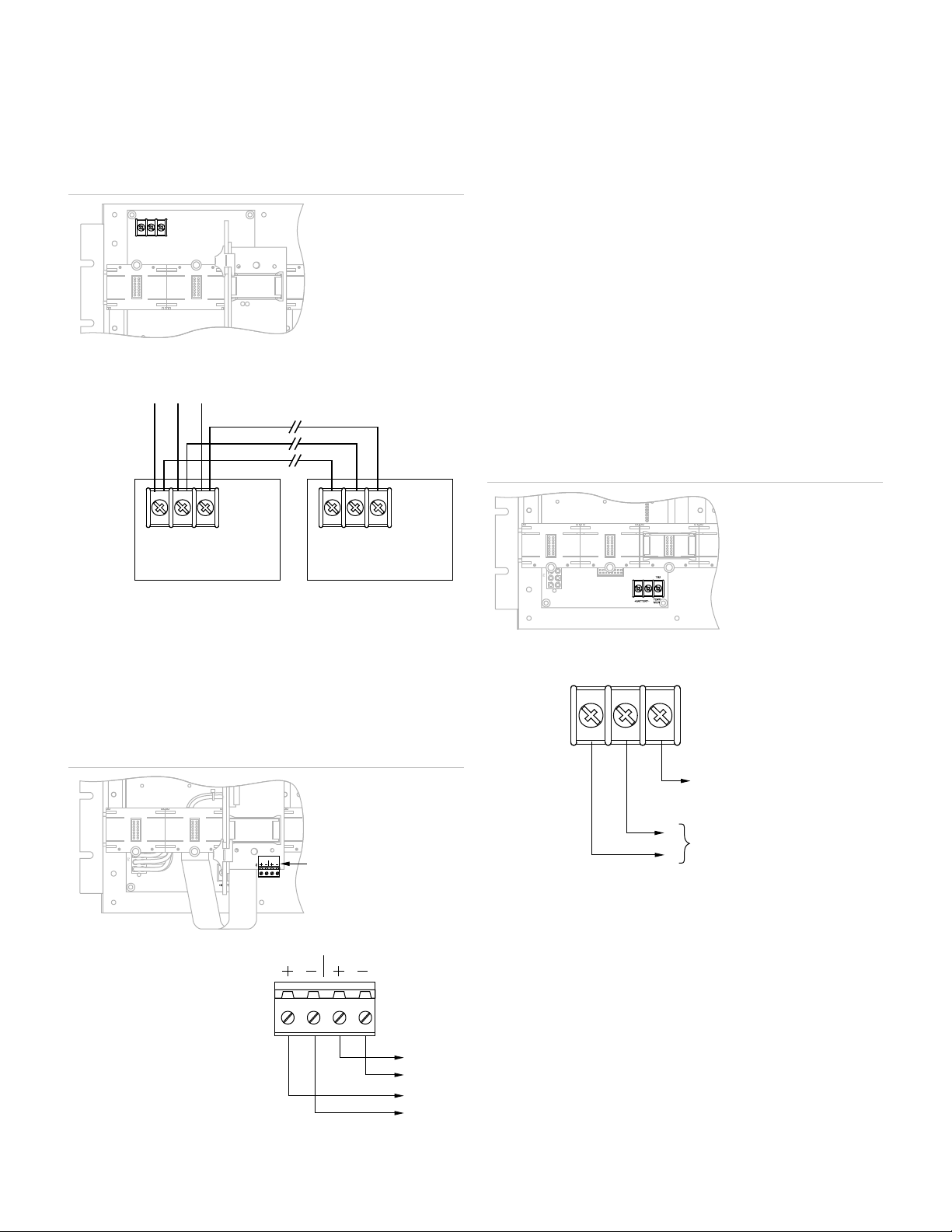
Installation
Installing a heat sink assembly
Heat sink assemblies are installed on the rail chassis behind the rail
module connectors. Refer to Figure 1.
To install a heat sink assembly:
1. Attach the heat sink assembly to the four threaded mounting studs
on the rail chassis using lock nuts provided in the hardware kit.
2. Secure the bottom edge of the heat sink assembly to the threaded
standoffs on the rail chassis using screws provided in the
hardware kit.
3. Secure the top edge of the heat sink assembly to the rail chassis
using the two threaded standoffs provided in the hardware kit.
4. Attach the AC terminal block cover to the threaded standoffs using
two #6-32 x 1/2 pan head screws.
Notes
•Always mount the heat sink assembly for the primary power supply
onto the left mounting space of the rail chassis in which the central
processor module is installed.
•Booster supplies, if installed, can be mounted on any rail chassis,
but no more than three booster supplies may be installed in the
same enclosure.
TB1
P3
TB2
P2
+BATTERY-MON
TEMP
TB1
AUXILIARY POWER
1 2
Heat sink
assembly
Monitor
module