Abatron BDI2000 User manual

bdiAccess
JTAG interface library
PowerPC 6xx/7xx/82xx/83xx/7400/7410
Installation Manual
Manual Version 1.12 for BDI2000
© 1992-2009 ABATRON AG

bdiAccessJTAG interface library, BDI2000 (PPC6xx/7xx/82xx/83xx) Installation Manual 2
© Copyright 1992-2009 by ABATRON AG V 1.12
1 Introduction ................................................................................................................................. 3
1.1 BDI2000................................................................................................................................. 3
2 Installation ................................................................................................................................... 4
2.1 Connecting the BDI2000 to Target ........................................................................................ 4
2.1.1 Changing Target Processor Type ................................................................................ 6
2.2 Connecting the BDI2000 to Power Supply ............................................................................ 7
2.3 Status LED «MODE»............................................................................................................. 8
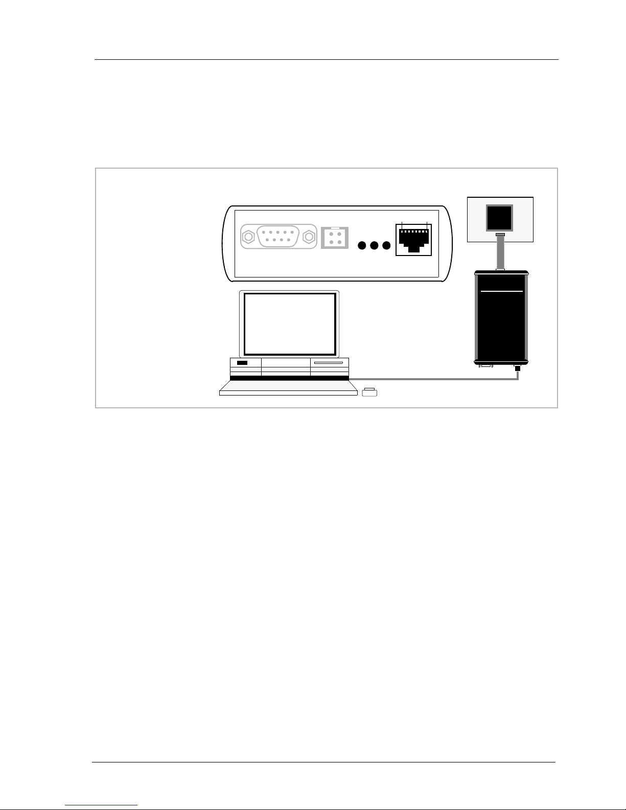
2.4 Connecting the BDI2000 to the Host ..................................................................................... 9
2.4.1 Serial line communication ............................................................................................ 9
2.4.2 Ethernet communication ............................................................................................ 10
2.5 Installation of the bdiAccess Software................................................................................. 11
2.6 BDI2000 Setup/Update........................................................................................................ 12
2.6.1 Linux/Unix Hosts ........................................................................................................ 12
2.6.2 Windows Hosts .......................................................................................................... 13
2.6.3 Recover procedure..................................................................................................... 14
3 Specifications............................................................................................................................ 15
4 Environmental notice................................................................................................................ 16
5 Declaration of Conformity (CE)................................................................................................ 16
6 Warranty..................................................................................................................................... 17
Appendices
A Troubleshooting ....................................................................................................................... 18
B Maintenance.............................................................................................................................. 19
C Trademarks ............................................................................................................................... 21

bdiAccessJTAG interface library, BDI2000 (PPC6xx/7xx/82xx/83xx) Installation Manual 3
© Copyright 1992-2009 by ABATRON AG V 1.12
1 Introduction
The bdiAccess library can be used to access the BDI2000 functions. With this library, a program run-
ning on a Windows/Linux/Unix host can take advantage of the JTAG interface of a PPC6xx/7xx/82xx/
83xx target processor and execute the following tasks:
• Read/Write target registers
• Read/Write target memory
• Reset/Startup target
• Flash programming
• Start/Stop program execution
This Installation Manual shows how to connect the BDI2000 to a PowerPC target and how to install
the bdiAccess software. The interface to the library is defined in a different document that is target
independent.
1.1 BDI2000
The BDI2000 is a processor system in a small box. It implements the interface between the JTAG
pins of the target CPU and a 10Base-T Ethernet / RS232 connector. The firmware and the program-
mable logic of the BDI2000 can be updated by the user with a simple Windows based configuration
program. The BDI2000 supports 1.8 – 5.0 Volts target systems (3.0 – 5.0 Volts target systems with
Rev. B).
PC / Unix
Host
BDI2000
Target System
JTAG Interface
Ethernet (10 BASE-T)
PPC
82xx
BDI2000
Target System
JTAG Interface
PPC
82xx
RS232

bdiAccessJTAG interface library, BDI2000 (PPC6xx/7xx/82xx/83xx) Installation Manual 4
© Copyright 1992-2009 by ABATRON AG V 1.12
2 Installation
2.1 Connecting the BDI2000 to Target
The cable to the target system is a 16 pin flat ribbon cable. In case where the target system has an
appropriate connector, the cable can be directly connected. The pin assignment is in accordance with
the PowerPC COP connector specification.
In order to ensure reliable operation of the BDI (EMC, runtimes, etc.) the target cable length must not
exceed 20 cm (8").
For BDI TARGET B connector signals see table on next page.
!
COP/JTAG Connector
BDI2000
Target System
MPC 1 15
16
2
The green LED «TRGT» marked light up when target is powered up
BDI TRGT MODE TARGET A TA R G E T B
15 1
16 2
82xx
1 - TDO
2 - QACK
3 - TDI
4 - TRST
5 - HALTED
6 - Vcc Target
7 - TCK
8 - NC (RXD)
9 - TMS
10 - NC (TXD)
11 - SRESET
12 - GROUND
13 - HRESET
14 - NC (key)
15 - CKSTP_OUT
16 - GROUND

bdiAccessJTAG interface library, BDI2000 (PPC6xx/7xx/82xx/83xx) Installation Manual 5
© Copyright 1992-2009 by ABATRON AG V 1.12
BDI TARGET B Connector Signals:
Pin Name Describtion
1TDO JTAG Test Data Out
This input to the BDI2000 connects to the target TDO pin.
2IO0 General purpose I/O
This output of the BDI2000 connects to the target QACK pin. Currently not used.
3TDI JTAG Test Data In
This output of the BDI2000 connects to the target TDI pin.
4TRST JTAG Test Reset
This output of the BDI2000 resets the JTAG TAP controller on the target.
5IN0 General purpose Input
This input to the BDI2000 connects to the target HALTED pin. Currently not used.
6 Vcc Target 1.8 – 5.0V:
This is the target reference voltage. It indicates that the target has power and it is also used
to create the logic-level reference for the input comparators. It also controls the output logic
levels to the target. It is normally fed from Vdd I/O on the target board.
3.0 – 5.0V with Rev. B :
This input to the BDI2000 is used to detect if the target is powered up. If there is a current
limiting resistor between this pin and the target Vdd, it should be 100 Ohm or less.
7TCK JTAG Test Clock
This output of the BDI2000 connects to the target TCK pin.
8 <reseved>
9TMS JTAG Test Mode Select
This output of the BDI2000 connects to the target TMS line.
10 <reseved>
11 SRESET Soft-Reset
This open collector output of the BDI2000 connects to the target SRESET pin.
12 GROUND System Ground
13 HRESET Hard-Reset
This open collector output of the BDI2000 connects to the target HRESET pin.
14 <reseved>
15 IN1 General purpose Input
This input to the BDI2000 connects to the target CKSTP_OUT pin. Currently not used.
16 GROUND System Ground

bdiAccessJTAG interface library, BDI2000 (PPC6xx/7xx/82xx/83xx) Installation Manual 6
© Copyright 1992-2009 by ABATRON AG V 1.12
2.1.1 Changing Target Processor Type
Before you can use the BDI2000 with an other target processor type (e.g. CPU32 <--> PPC), a new
setup has to be done (see Appendix A). During this process the target cable must be disconnected
from the target system. The BDI2000 needs to be supplied with 5 Volts via the POWER connector.
For more information see chapter 2.2.1 «External Power Supply».
To avoid data line conflicts, the BDI2000 must be disconnected from the target system while
programming the logic for an other target CPU.
!

bdiAccessJTAG interface library, BDI2000 (PPC6xx/7xx/82xx/83xx) Installation Manual 7
© Copyright 1992-2009 by ABATRON AG V 1.12
2.2 Connecting the BDI2000 to Power Supply
The BDI2000 needs to be supplied with 5 Volts (max. 1A) via the POWER connector. The available
power supply from Abatron (option) or the enclosed power cable can be directly connected. In order
to ensure reliable operation of the BDI2000, keep the power supply cable as short as possible.
For error-free operation, the power supply to the BDI2000 must be between 4.75V and 5.25V DC.
The maximal tolerable supply voltage is 5.25 VDC. Any higher voltage or a wrong polarity
might destroy the electronics.
Please switch on the system in the following sequence:
• 1 --> external power supply
• 2 --> target system
!
BDI TRGT MODE TARGET A TARGET B
POWER
1 - Vcc (+5V)
2 - VccTGT
3 - GROUND
4 - NOT USED
Connector
The green LED «BDI» marked light up when 5V power is connected to the BDI2000
RS232 POWER LI TX RX 10 BASE-T
1 Vcc
2
GND 3
4
Rev. B Version

bdiAccessJTAG interface library, BDI2000 (PPC6xx/7xx/82xx/83xx) Installation Manual 8
© Copyright 1992-2009 by ABATRON AG V 1.12
2.3 Status LED «MODE»
The built in LED indicates the following BDI states:
MODE LED BDI STATES
OFF The BDI is ready for use, the firmware is already loaded.
ON The power supply for the BDI2000 is < 4.75VDC.
BLINK The BDI «loader mode» is active (an invalid firmware is loaded or loading firmware is active).
BDI TRGT MODE TARGET A TARGET B

bdiAccessJTAG interface library, BDI2000 (PPC6xx/7xx/82xx/83xx) Installation Manual 9
© Copyright 1992-2009 by ABATRON AG V 1.12
2.4 Connecting the BDI2000 to the Host
2.4.1 Serial line communication
The host is connected to the BDI through the serial interface (COM1...COM4). The communication
cable between BDI and Host is a serial cable (RXD / TXD are crossed). There is the same connector
pinout for the BDI and for the Host side (Refer to Figure below).
RS232 Connector
(for PC host)
BDI2000
Target System
RS232
PC Host
1 - NC
2 - RXD data from host
3 - TXD data to host
4 - NC
5 - GROUND
6 - NC
7 - NC
8 - NC
9 - NC
RS232 POWER LI TX RX 10 BASE-T
54321
9876
PPC

bdiAccessJTAG interface library, BDI2000 (PPC6xx/7xx/82xx/83xx) Installation Manual 10
© Copyright 1992-2009 by ABATRON AG V 1.12
2.4.2 Ethernet communication
The BDI2000 has a built-in 10 BASE-T Ethernet interface (see figure below). Connect an UTP (Un-
shilded Twisted Pair) cable to the BD2000. For thin Ethernet coaxial networks you can connect a
commercially available media converter (BNC-->10 BASE-T) between your network and the
BDI2000. Contact your network administrator if you have questions about the network.
The following explains the meanings of the built-in LED lights:
LED Name Description
LI Link When this LED light is ON, data link is successful between the UTP
port of the BDI2000 and the hub to which it is connected.
TX Transmit When this LED light BLINKS, data is being transmitted through the UTP
port of the BDI2000
RX Receive When this LED light BLINKS, data is being received through the UTP
port of the BDI2000
10 BASE-T
PC / Unix
Host
Target System
Ethernet (10 BASE-T)
1 - TD+
2 - TD-
3 - RD+
4 - NC
5 - NC
6 - RD-
7 - NC
8 - NC
Connector
BDI2000
RS232 POWER LI TX RX 10 BASE-T
18 PPC

bdiAccessJTAG interface library, BDI2000 (PPC6xx/7xx/82xx/83xx) Installation Manual 11
© Copyright 1992-2009 by ABATRON AG V 1.12
2.5 Installation of the bdiAccess Software
On the enclosed CD you will find the bdiAccess library, the BDI configuration software and the firm-
ware required for the BDI. Copy the appropriate files to a directory on your hard disk.
Windows and Linux/Unix hosts:
manual.pdf This installation manual in pdf format
bdiacc.pdf The bdiAccess interface specification in pdf format
b20copfw.xxx Firmware for BDI2000 for PPC6xx/7xx/82xx/83xx targets
copjed20.xxx JEDEC file for the BDI2000 (Rev. A/B) logic device programming
copjed21.xxx JEDEC file for the BDI2000 (Rev. C) logic device programming
Only for Windows hosts:
b20copfw.exe Setup program (WIN32 application)
bdiifc32.dll The bdiAccess library (WIN32-DLL)
bdiifc32.lib The import library for the bdiAccess DLL (WIN32)
bdiifc.h The C header file showing the interface to the bdiAccess DLL
Only for Linux/Unix hosts:
bdiaccux.zip Archive with the bdiAccess sources for Linux/Unix hosts
bdisetup.zip Archive with the BDI setup utility sources for Linux/Unix hosts

bdiAccessJTAG interface library, BDI2000 (PPC6xx/7xx/82xx/83xx) Installation Manual 12
© Copyright 1992-2009 by ABATRON AG V 1.12
2.6 BDI2000 Setup/Update
First make sure that the BDI is properly connected (see Chapter 2.1 to 2.4). The BDI must be con-
nected via RS232 to the host.
To avoid data line conflicts, the BDI2000 must be disconnected from the target system while
programming the logic for an other target CPU (see Chapter 2.1.1).
2.6.1 Linux/Unix Hosts
In order to update the firmware / logic of the BDI and to set the network parameters, a setup tool is
included for Linux/Unix hosts. In the ZIP Archive bdisetup.zip are all sources to build this utility.
This command line utility can be used to update the firmware and logic of the BDI2000. It is also used
to transfer the network configuration. There are 4 tasks the utility can process:
• Reading the current loaded firmware / logic version
• Erasing the firmware and logic
• Updating the firmware and logic
• Storing the network configuration parameters into the BDI flash
Every of this task is started by executing the setup utility with different parameters. The first param-
eter always selects the task to execute:
bdisetup { -v | -e | -u | -c } [additional parameters]
-v Read version
-e Erase firmware and logic
-u Update firmware and/or logic
-c Store network configuration
There are two common additional parameters which define the serial port and the serial baudrate:
-pP Port to use, replace P with the port to use e.g. /dev/ttyS0
-bB Baudrate to use, replace B with 9, 19, 38, 57 or 115
Additional parameters for update (-u):
-aA Application type, replace A with GDB, ADA, TOR or ACC
-tT Target type, replace T with CPU32,PPC400,PPC600,PPC700,MPC800,
ARM,TRICORE,MCF,HC12 or MCORE
-dD Replace D with the directory with the firmware/logic files
Additional parameters for network configuration (-c):
-iI Replace I with the BDI IP address (format: xxx.xxx.xxx.xxx)
-mM Replace M with the subnet mask.
A subnet mask of 255.255.255.255 disables the gateway function
-gG Replace G with the default gateway IP address
All parameters have default values. See function main(). You may adjust this default values for your
convenience. See also bdisetup.c and document BDIACC.PDF for additional information
To build the setup utility use: gcc bdisetup.c bdidll.c -o bdisetup
!

bdiAccessJTAG interface library, BDI2000 (PPC6xx/7xx/82xx/83xx) Installation Manual 13
© Copyright 1992-2009 by ABATRON AG V 1.12
2.6.2 Windows Hosts
After starting the Windows setup tool, the following dialog box will be displayed.
dialog box «BDI2000 Update/Setup»
The following options allow you to update the BDI2000 firmware and store the network parameters:
Port Select the communication port where the BDI2000 is connected during
this setup session.
Speed Select the baudrate used to communicate with the BDI2000 loader during
this setup session.
Connect Click on this button to establish a connection with the BDI2000 loader.
Once connected, the BDI2000 remains in loader mode until it is restarted
or this dialog box is closed.
Current Press this button to read back the current loaded BDI2000 firmware ver-
sion. The current firmware version will be displayed.
Erase Press this button to erase the current loaded firmware.
Update This button is only active if there is a newer firmware version present in the
execution directory of the setup software. Press this button to write the
new firmware into the BDI2000 flash memory.

bdiAccessJTAG interface library, BDI2000 (PPC6xx/7xx/82xx/83xx) Installation Manual 14
© Copyright 1992-2009 by ABATRON AG V 1.12
BDI IP Address Enter the IP address for the BDI2000.
Use the following format: xxx.xxx.xxx.xxx e.g.151.120.25.101
Ask your network administrator for assigning an IP address to this
BDI2000. Every BDI2000 in your network needs a different IP address.
Subnet Mask Enter the subnet mask of the network where the BDI is connected to.
Use the following format: xxx.xxx.xxx.xxxe.g.255.255.255.0
A subnet mask of 255.255.255.255 disables the gateway feature.
Ask your network administrator for the correct subnet mask.
Default Gateway Enter the IP address of the default gateway. Ask your network administra-
tor for the correct gateway IP address. If the gateway feature is disabled,
you may enter 255.255.255.255 or any other value.
Transmit Click on this button to store the configuration in the BDI2000 flash
memory.
2.6.3 Recover procedure
In rare instances you may not be able to load the firmware in spite of a correctly connected BDI (error
of the previous firmware in the flash memory). Before carrying out the following procedure, check
the possibilities in Appendix «Troubleshooting». In case you do not have any success with the
tips there, do the following:
• Switch OFF the power supply for the BDI and open the unit as
described in Appendix «Maintenance»
• Place the jumper in the «INIT MODE» position
• Connect the power cable or target cable if the BDI is powered
from target system
• Switch ON the power supply for the BDI again and wait until the
LED «MODE» blinks fast
• Turn the power supply OFF again
• Return the jumper to the «DEFAULT» position
• Reassemble the unit as described in Appendix «Maintenance»
INIT MODE
DEFAULT

bdiAccessJTAG interface library, BDI2000 (PPC6xx/7xx/82xx/83xx) Installation Manual 15
© Copyright 1992-2009 by ABATRON AG V 1.12
3 Specifications
Operating Voltage Limiting 5 VDC ± 0.25 V
Power Supply Current typ. 500 mA
max. 1000 mA
RS232 Interface: Baud Rates 9’600,19’200, 38’400, 57’600,115’200
Data Bits 8
Parity Bits none
Stop Bits 1
Network Interface 10 BASE-T
Serial Transfer Rate between BDI and Target up to 16 Mbit/s
Supported target voltage 1.8 – 5.0 V (3.0 – 5.0 V with Rev. B)
Operating Temperature + 5 °C ... +60 °C
Storage Temperature -20 °C ... +65 °C
Relative Humidity (noncondensing) <90 %rF
Size 190 x 110 x 35 mm
Weight (without cables) 420 g
Host Cable length (RS232) 2.5 m
Specifications subject to change without notice

bdiAccessJTAG interface library, BDI2000 (PPC6xx/7xx/82xx/83xx) Installation Manual 16
© Copyright 1992-2009 by ABATRON AG V 1.12
4 Environmental notice
Disposal of the equipment must be carried out at a designated disposal site.
5 Declaration of Conformity (CE)

bdiAccessJTAG interface library, BDI2000 (PPC6xx/7xx/82xx/83xx) Installation Manual 17
© Copyright 1992-2009 by ABATRON AG V 1.12
6 Warranty
ABATRON Switzerland warrants the physical CD, cable, BDI2000 and physical documentation to be
free of defects in materials and workmanship for a period of 36 months following the date of purchase
when used under normal conditions.
In the event of notification within the warranty period of defects in material or workmanship,
ABATRON will replace/repair defective CD, cable, BDI2000 or documentation. The remedy for
breach of this warranty shall be limited to replacement and shall not encompass any other damages,
including but not limited loss of profit, special, incidental, consequential, or other similar claims.
ABATRON Switzerland specifically disclaims all other warranties- expressed or implied, including but
not limited to implied warranties of merchantability and fitness for particular purposes - with respect
to defects in the CD, cable, BDI2000 and documentation, and the program license granted herein,
including without limitation the operation of the program with respect to any particular application,
use, or purposes. In no event shall ABATRON be liable for any loss of profit or any other commercial
damage, including but not limited to special, incidental, consequential, or other damages.
Failure in handling which leads to defects are not covered under this warranty. The warranty is void
under any self-made repair operation except exchanging the fuse.

bdiAccessJTAG interface library, BDI2000 (PPC6xx/7xx/82xx/83xx) Installation Manual 18
© Copyright 1992-2009 by ABATRON AG V 1.12
Appendices
A Troubleshooting
Problem
The firmware can not be loaded.
Possible reasons
• The BDI is not correctly connected with the target system (see chapter 2).
• The power supply of the target system is switched off or not in operating range
(4.75 VDC ... 5.25 VDC) --> MODE LED is OFF or RED
• The built in fuse is damaged --> MODE LED is OFF
• The BDI is not correctly connected with the Host (see chapter 2).
• A wrong communication port (Com 1...Com 4) is selected.
Problem
No working with the target system (loading firmware is ok).
Possible reasons
• Wrong pin assignment (BDM/JTAG connector) of the target system (see chapter 2).
• Target system initialization is not correctly --> enter an appropriate target initialization list.
• An incorrect IP address was entered (BDI2000 configuration)
• BDM/JTAG signals from the target system are not correctly (short-circuit, break, ...).
• The target system is damaged.
Problem
Network processes do not function (loading the firmware was successful)
Possible reasons
• The BDI2000 is not connected or not correctly connected to the network (LAN cable or media
converter)
• An incorrect IP address was entered (BDI2000 configuration)

bdiAccessJTAG interface library, BDI2000 (PPC6xx/7xx/82xx/83xx) Installation Manual 19
© Copyright 1992-2009 by ABATRON AG V 1.12
B Maintenance
The BDI needs no special maintenance. Clean the housing with a mild detergent only. Solvents such
as gasoline may damage it.
If the BDI is connected correctly and it is still not responding, then the built in fuse might be damaged
(in cases where the device was used with wrong supply voltage or wrong polarity). To exchange the
fuse or to perform special initialization, please proceed according to the following steps:
Observe precautions for handling (Electrostatic sensitive device)
Unplug the cables before opening the cover.
Use exact fuse replacement (Microfuse MSF 1.6 AF).
!
1
2
3
1.1 Unplug the cables
BDI TRGT MODE BDI MAIN BDI OPTION
2.1 Remove the two plastic caps that cover the screws on target front side
2.2 Remove the two screws that hold the front panel
3.1 While holding the casing, remove the front panel and the red elastig sealing
(e.g. with a small knife)
front panel
elastic sealing
casing

bdiAccessJTAG interface library, BDI2000 (PPC6xx/7xx/82xx/83xx) Installation Manual 20
© Copyright 1992-2009 by ABATRON AG V 1.12
Observe precautions for handling (Electrostatic sensitive device)
Unplug the cables before opening the cover.
Use exact fuse replacement (Microfuse MSF 1.6 AF).
4
5
4.1 While holding the casing, slide carefully the print in position as shown in
5.1 Slide back carefully the print. Check that the LEDs align with the holes in the
front panel
elastic sealing
Reinstallation
back panel.
5.2 Push carefully the front panel and the red elastig sealing on the casing.
Check that the LEDs align with the holes in the front panel and that the
5.3 Mount the screws (do not overtighten it)
5.4 Mount the two plastic caps that cover the screws
5.5 Plug the cables
position of the sealing is as shown in the figure below.
casing
figure below
Pull-out carefully the fuse and replace it
Type: Microfuse MSF 1.6AF
Manufacturer: Schurter
Jumper settings
DEFAULT INIT MODE
back panel
Fuse Position
Fuse Position
Version B
Version A
!
Other manuals for BDI2000
10
Table of contents