Eelectron AD84C01KNX User manual

AD84C01KNXFI000030101_HANDBOOK_EN.DOCX
AD84C01KNX - ANALOG / DIGITAL MODULE Handbook
Eel ect r on Sp A, Vi a Mon t everd i 6 ,
I-20025 Legnano (MI), Italia
Tel: +39 03 31.5008 02 Fax:+39 03 31.564826
E-mail:info@eelectron.com Web:www.eelectron.com
C.F. e P.IVA 11666 76 0159
Tr ib u n ale d i M il an o 3 59 15 7-8760-07
CCIAA M i lan o 1 48 549
1/27
Product Hand book
AD84C01KNX
Analog / Digital Module 8 Input / 4 led Out put
Docum ent
Version: 1.1
Date:
31/01/2019

AD84C01KNXFI000030101_HANDBOOK_EN.DOCX
AD84C01KNX - ANALOG / DIGITAL MODULE Handbook
Eel ect r on Sp A, Vi a M on t everd i 6,
I-20025 Legnano (MI), Italia
Tel: +39 03 31.5008 02 Fax:+39 03 31.564826
E-mail:info@eelectron.com Web:www.eelectron.com
C.F. e P.IVA 11666760159
Tr ib u n ale d i M il an o 3 59 15 7-8760-07
CCIAA M i lan o 1 48 549
2/27
INDEX
1. Gen eral int rod uct ion ......................................................................................................................................................................... 5
2. Prod u ct overview ................................................................................................................................................................................. 5
3. Installat ion instructions .................................................................................................................................................................. 6
4. Param et ri Gen erali.............................................................................................................................................................................. 6
5. Inp ut s configurat ion .......................................................................................................................................................................... 6
6. Digital inputs.......................................................................................................................................................................................... 7
Activation on press.................................................................................................................................................................................... 7
Activation on press / release ............................................................................................................................................................... 7
Activation on short and long press................................................................................................................................................ 7
Dim m ing ........................................................................................................................................................................................................... 8
Sh u t t er an d Bl in d s ..................................................................................................................................................................................... 8
Sc en e ................................................................................................................................................................................................................... 8
Com m an d s seq u en c es............................................................................................................................................................................ 9
Com m an d seq u en ces (1 b i t )............................................................................................................................................................... 9
Input count er (pulse counter)......................................................................................................................................................... 10
Set RGB color.............................................................................................................................................................................................. 10
MUR / DND ................................................................................................................................................................................................... 10
Loo p am on g val ues ................................................................................................................................................................................ 10
7. Led ou t p ut ............................................................................................................................................................................................. 11
8. Analog inputs...................................................................................................................................................................................... 11
Tem p er at u r e sen so r description............................................................................................................................................... 11
Tem p er at u r e sen so r parameters.............................................................................................................................................. 12
9. Th erm ost at Fu n ct ion ..................................................................................................................................................................... 12
Set p o i n t Set t i n g s ..................................................................................................................................................................................... 12
SETPOINT Ob ject .................................................................................................................................................................................... 12
HVAC MODE obj. (switched heat / cool).................................................................................................................................. 12
HVAC MODE obj. (autom atic heat / cool) ............................................................................................................................... 13
SETPOINT COMFORT, STANDBY, ECONOMY......................................................................................................................... 13
COM FORT Ob ject ..................................................................................................................................................................................... 13
WINDOW CONTACT Object .............................................................................................................................................................. 13
SETPOINT ADJUSTMENT ob ject .................................................................................................................................................... 14
KNX probe tem perature obj............................................................................................................................................................ 14
ACTUAL SETPOINT ob ject .................................................................................................................................................................. 14
Tw o p o in t s on /o ff ..................................................................................................................................................................................... 14
Int egral p rop ort ion al cont rol PW M ............................................................................................................................................. 15
Integral proport ional cont r. continuous................................................................................................................................... 15
Fan co il o n /off ............................................................................................................................................................................................. 15
Manage valve independently .......................................................................................................................................................... 17
Fan coil con t rol PI.................................................................................................................................................................................... 17
Additional valve ........................................................................................................................................................................................ 17
Additional valve 6 ways....................................................................................................................................................................... 18
Force fan coi l sp eed ............................................................................................................................................................................... 18
Vent ilation m ode ..................................................................................................................................................................................... 18
Tem p er at u r e p r ob e f ai lu r e / o u t of r an g e m easu r em en t ............................................................................................. 19
Tem p erature alarm object ................................................................................................................................................................ 19

AD84C01KNXFI000030101_HANDBOOK_EN.DOCX
AD84C01KNX - ANALOG / DIGITAL MODULE Handbook
Eel ect r on Sp A, Vi a M on t everd i 6,
I-20025 Legnano (MI), Italia
Tel: +39 03 31.5008 02 Fax:+39 03 31.564826
E-mail:info@eelectron.com Web:www.eelectron.com
C.F. e P.IVA 11666760159
Tr ib u n ale d i M il an o 3 59 15 7-8760-07
CCIAA M i lan o 1 48 549
3/27
10. Th er m ost at b eh avi ou r o n b u s fail u re, r ec overy an d d ow n l oad ...................................................................... 20
Behaviour on bus voltage failure .................................................................................................................................................. 20
Behaviour on bus voltage recovery ............................................................................................................................................. 20
Behaviour on ETS Dow nload ........................................................................................................................................................... 20
11. Log ics........................................................................................................................................................................................................ 20
12. Virtual holder ...................................................................................................................................................................................... 22
How it works............................................................................................................................................................................................... 22
Com m u n i cat i on Ob j ect s..................................................................................................................................................................... 23
Param et ers Gen eral ............................................................................................................................................................................ 23
Param et ers Rem ot e in p ut s............................................................................................................................................................ 24
Rem ot e Sen sor In p ut s (Glob al Enable)..................................................................................................................................... 25
13. Wrong application download.................................................................................................................................................. 25

AD84C01KNXFI000030101_HANDBOOK_EN.DOCX
AD84C01KNX - ANALOG / DIGITAL MODULE Handbook
Eel ect r on Sp A, Vi a M on t everd i 6,
I-20025 Legnano (MI), Italia
Tel: +39 03 31.5008 02 Fax:+39 03 31.564826
E-mail:info@eelectron.com Web:www.eelectron.com
C.F. e P.IVA 11666760159
Tr ib u n ale d i M il an o 3 59 15 7-8760-07
CCIAA M i lan o 1 48 549
4/27
Any inform ation inside this m anual can be changed w ithout advice.
Th is h an d b o ok c an b e d ow n l oad freel y f rom t h e website:
www.eelectron.com
Exclusion of liab ilit y:
Despite checking that the contents of this docum ent m atch the hardw are and softw are, deviations cannot be
com pletely excluded. We therefore cannot accept any liability for this.
Any necessary corrections will be incorporated into newer versions of this m anual.
Sym b o l for rel evan t in form at ion
Sym b o l for w ar n in g
DISPOSAL : Th e cro ssed -out bin sym bol on the equipm ent or packaging m eans the product m ust not be
included w ith other general w aste at the end of its working life. The user m ust take the worn product to a sorted
waste centre,or return it to the retailer when purchasing a new one. An efficient sorted waste collection for the
environm entally friendly disposal of t he used device, or its subsequent recycling, helps avoid the potential
negative effects on the environm ent and people s h eal t h , an d en co urages t h e re-use and/or recycling of the
construction m aterials

AD84C01KNXFI000030101_HANDBOOK_EN.DOCX
AD84C01KNX - ANALOG / DIGITAL MODULE Handbook
Eel ect r on Sp A, Vi a M on t everd i 6,
I-20025 Legnano (MI), Italia
Tel: +39 03 31.5008 02 Fax:+39 03 31.564826
E-mail:info@eelectron.com Web:www.eelectron.com
C.F. e P.IVA 11666760159
Tr ib u n ale d i M il an o 3 59 15 7-8760-07
CCIAA M i lan o 1 48 549
5/27
1. Gen er al i n t r o d u c t i o n
Th i s m an u al i s intended for use by KNX® installers
and describes functions and param eters of the
AD84C01KNX m odule and how you can change
set t in gs an d co n figu rat i on s u sin g t h e ETS soft w ar e
tool.
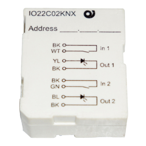
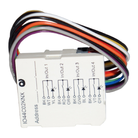
Th e AD84C01KN X d evice is a in w al l m od u le w it h 8
inputs and 4 LED outputs.
The 8 inputs are for dry contacts (free from
potential); inputs from 1 to 4 are digital, inputs 5 to
8 can be configured as digital or analogical to
interface NTC tem perature probes (code eelectron
TS01A0 1A CC or TS01B0 1A CC).
Th e o u t p u t s can d r ive l ow vo lt age LEDs; use high
efficiency LED code eelectron LD00A01ACC (blue) or
LD00A1 1A CC (w h it e).
Th e A D 84 C01 KN X m o d u l e i s d esi g n ed f o r u se i n
domestic and building installations (eg offices,
hotels, private homes, etc.).
2. Prod uct overview
Main functions digital inputs 1 ÷ 8
Digital inputs can be connected to buttons or
sw i t c h es an d c an b e u sed fo r:
1-bit commands: loads activation / deactivation
com m ands (ON / OFF / TOGGLE) with short
pressure or with long and short pressure
differentiation
1 byte com m ands (0-255 or HVAC com m ands or
% value com m ands).
Sen d in g lon g ac t io n t el eg ram s t o t h e sam e sh o rt
action address or to a d ifferent group address
Com m an d s fo r cyclic sen d in g
Seq u en ces (3 c om m an d s t h at m i x 1 b i t / 1 b yt e
objects) with different group addresses - in short
and long press m ode or in sw it ching m ode
Dim m er m anagem ent (w ith single button or
with double button)
Roller shu t t ers an d b lin d s m anagem en t (w it h
sin g le b u t t o n o r w i t h d ou b le b u t t on )
Con t ro l seq u en ces w it h 1 b it t o m an ag e
sw it ch in g on / o ff ligh t s or rows of lights
Input count ers (only input s from 1 to 4)
RGB color set t in g w it h fixed value (short
pressure) or color change (long pressure); 1 byte
datapoint or 3 byte selectable
MUR / DND (Make Up Room - / Do Not Disturb),
function with built-in logics
Loop function between values to send step by
st ep a seq u en c e o f val u es of 1 byte
Main functions analog input si 5 ÷ 8
Inputs 5 to 8 can b e configured as analogue for t he
connection of NTC tem perature probes
It is possib le t o en able 4 com plet e t herm ost ats
modules; each thermostat module manages 2
st ages w it h in t egrat ed PI con t roller for d rivin g
heating and cooling equipment, valves, 2 and 4 pipe
fan coils, etc..
NTC probes :
For NTC t em p er at u re p r ob e t h e fol low in g eelect ron
code accessories m ust be used:
TS01A01A CC (fro m -20°C to +100°C)
TS01B01A CC (fro m -50°C to +60°C)
NTC probes main functions:
Con fig u red as t em p er at u re sen sors (4 sen so rs) -
main functions:
2 different tem perature thresholds to activate
alarm s / w arnings w it h 1 bit telegram s
En able / disable alarm s / alerts via 1-bit objects
Con fig u red as t h erm ost at s (4 thermostats) - main
functions:
Different Control Algorithm s: 2-point on / off;
PW M; con t in uou s con t rol / Fan Coil con t rol
Different m odes of operation m ode setting:
Autom atic HVAC / HVAC Manual / Setpoint
Additional com m and for 2nd st ag e
management
Window contact m anagem ent
Additional external probe (optional)

AD84C01KNXFI000030101_HANDBOOK_EN.DOCX
AD84C01KNX - ANALOG / DIGITAL MODULE Handbook
Eel ect r on Sp A, Vi a M on t everd i 6,
I-20025 Legnano (MI), Italia
Tel: +39 03 31.5008 02 Fax:+39 03 31.564826
E-mail:info@eelectron.com Web:www.eelectron.com
C.F. e P.IVA 11666760159
Tr ib u n ale d i M il an o 3 59 15 7-8760-07
CCIAA M i lan o 1 48 549
6/27
Logic function and Virt ual Hold er function
Th e d evice in c lu d es so m e log ic fun ct io n s an d a
logic for the autom atic detection of the presence in
room called "Virtual Holder"
Logics main functions
2 input object and 1 out put obj for every logic
Delay, retransm ission of telegram s
NOT / AND / OR / NAND / NOR / XOR / XNOR
Bit to Byte conversion
Byte to Bit conversion
1,2,4 Bytes Threshold
Free exp ressio n s w it h 4 in p ut o b ject s and 1 out
object
3. Inst allat ion inst ruct ions
Th e d evice m ay b e u sed f or p erm an en t in d oor
installations in dry locations within w all box
mounts.
WARNING
Device m ust be installed keeping a m inim um
distance of 4 mm between electrical power line
(m ain s) an d in p u t c ables or red / black bus cable.
Th e d evice m u st n o t b e con n ect ed t o 230V
cables
Th e p r evai li n g saf et y r u les m u st b e h eed ed .
Th e d evice m u st b e m o un t ed an d com m ission ed
by an authorized installer.
Th e ap p l icab le saf et y an d accid en t p r even t ion
regulations m ust be observed.
Th e d evic e m u st n o t b e op en ed . An y fau lt y
devices should be returned to manufacturer.
For p lan n in g an d co n st ru ct ion of el ect ric
installations, the relevant guidelines, regulations
and st andards of t he respective count ry are to be
considered.
KNX bus allow s you to rem otely send com m ands
to the system actuators. Always make sure that
the execution of remote commands do not lead
to hazardous situations, and that the user always
has a warning about which commands can be
activated rem otely.
Fo r f u r t h er i n f or m at i on p l ease vi sit :
www.eelectron.com
4. Param et ri Gen erali
KNX PARAMETER
SETTINGS
Delay on Pow er-up
5 ÷ 15 seconds
Th rou g h t h is p aram et er i s p ossib le t o set t h e d el ay of
transmission of telegrams after a power on by selecting
the time by which the device is allowed to send
telegrams.
In large syst em s aft er a pow er failure or shutdow n this
delay avoids to generate excessive traffic on the bus,
causing slow perform ance or a transmission block.
If there are different devices req uiring send ing telegram s
on the bus after a reset, these delays m ust be
programmed to prevent traffic congestion during the
initialization phase.
Th e i n p u t d et ect i on an d t he values of objects are
updated at the end of the transmission delay time
At the end of ETS program m ing the device behaves like
after a pow er on.
Virtual holder
disabled / enabled
By setting this param eter, you can enable a "virtual
holder", that is, a logical function that autom atically
recognizes the presence of a person in a room . This
feature can be used in hotel or sim ilar installations and
requires connection to other devices.
En ab l e alarm ob j . i np . <x >
disabled / enabled
By setting this param eter, a 1-bit communication object
is show n which is used to signal a m alfunction related to
the temperature sensor.
5. Inp ut s configurat ion
Inputs 1 to 4 are digital, while inputs 5 to 8 can be
configured as digital or analogical to interface NTC
temperature p rob es.

AD84C01KNXFI000030101_HANDBOOK_EN.DOCX
AD84C01KNX - ANALOG / DIGITAL MODULE Handbook
Eel ect r on Sp A, Vi a M on t everd i 6,
I-20025 Legnano (MI), Italia
Tel: +39 03 31.5008 02 Fax:+39 03 31.564826
E-mail:info@eelectron.com Web:www.eelectron.com
C.F. e P.IVA 11666760159
Tr ib u n ale d i M il an o 3 59 15 7-8760-07
CCIAA M i lan o 1 48 549
7/27
6. Digit al input s
With DIGITAL INPUT con figu rat ion each in d ivid u al
input can be configured to perform one of the
following functions:
Activation on press
Activation on press / release
Activation on short and long press
Dim m ing
Sh u t t er an d b l in ds
Scen e
Com m an d seq u en ces (sh o rt an d lon g p r ess)
Com m an d seq u en ces (t o gg l e f u n ct i on )
Com m an d seq u en ces 1 b i t
Input count er (pulse count er)
Set RGB c olo r
MUR/DND function
Loo p am on g val ues
Activation on press
on press" allow s you to configure the
sen d i n g of telegram s when the button is pressed;
device can also be configured to send periodic
messageswith repetition period.
KNX PARAMETER
SETTINGS
Telegram Associat ed
1 bit / 1 byte
It is possib le to send 1 b it or 1 b yte object s
Co n f i g u r at i o n s f or 1 b it object :
On
Off
To g g l e
Co n f igu rat i on s f o r 1 b y t e o b j ect :
Value 0-255 (g en er ic sig n ed in t )
Value 0-100% (scal in g valu e in st ep s o f 5 %)
HVAC Mode (DPT_HVACMod e 20.102)
KNX PARAMETER
SETTINGS
Cy cl i c sending w hen
button pressed
Never
0.3 sec.
0.4 sec.
0.5 sec.
0.8 sec
1.0 sec.
1.2 sec.
1.5 sec.
2.0 sec.
3.0 sec.
5.0 sec.
8.0 sec.
10 sec.
As long as the button is pressed, the telegram w ith
sel ec t ed size an d val u e is sen t cyc lic al ly; t h is
parameters defines the time interval between two
sen d ings
Activation on press / release
on press / release " allow s you to
configure the sending of telegram s when the
button is pressed and when it is released.
KNX PARAMETER
SETTINGS
Co m m u n i c at i o n o b j ec t
on release
disabled / enabled
if enabled, this param eter displays an additional
com m unication object (<Button x> Release Action) that
is transm itted on the release event, this object can be
associat ed w it h a group address other than the one
that sends the value associated with the pressure.
Activation on short and long press
Th e d iff eren t d u rat i on b et w een sh ort an d l on g p r ess
is defined by the param eter "Minim um tim e long
You can set t o sen d a t elegram s w it h different
values on short and long press or decide to send
com m ands only on one of this events.

AD84C01KNXFI000030101_HANDBOOK_EN.DOCX
AD84C01KNX - ANALOG / DIGITAL MODULE Handbook
Eel ect r on Sp A, Vi a M on t everd i 6,
I-20025 Legnano (MI), Italia
Tel: +39 03 31.5008 02 Fax:+39 03 31.564826
E-mail:info@eelectron.com Web:www.eelectron.com
C.F. e P.IVA 11666760159
Tr ib u n ale d i M il an o 3 59 15 7-8760-07
CCIAA M i lan o 1 48 549
8/27
When button is pressed then counting time starts; if
t h e b u t t on is released b efore t im e exceed s TPL
time, device executes the command associated
with the event of "short press" and if, on the
con t rary, TPL t im eout exp ires an d b ut t on is st ill
pressed then the command associated with the
Th e p aram et er s an d m od e of t ran sm ission o f
telegrams can be managed through "activation on
long and short press" are the same set with the
configuration "Activation of press / release " except
for the function of cyclic sending that is not
provided here.
Dim m ing
control a light dim mer using short and long pressof
the buttons.
Each b u t t on u ses 2 com m u nicat ion ob ject s:
1 bit dim ension for ON /OFF com m and associated
to short press operation
4 bit dim ension for brightness regulation associated
to long press operation
Param et er "Min im u
darker behaviour and step of each long press
action.
Sh u t t er an d Bl in d s
le
to control Roller Shutters or Blinds using short and
long press of the buttons.
Each in p u t u ses 2 co m m u n icat i on ob j ect s:
1 b it d im en sion for STEP /STOP com m an d
associated to short press operat ion
1 bit d im ension for UP / DOWN com m and
associated to long press operation
associated to long press act ion.
Scen e
button for scene management: learn and recall
scen e com m an d s.
Th ese d if feren t b eh avi ou r (r ecall an d learn ) ar e
performed through two different actions (short and
long press) of the button.
Learn scen e on long p ress act ion is en ab led b y a
parameter; "Min im um
set t h e m i n im u m d u r at i on o f l o n g p r ess.
KNX PARAMETER
SETTINGS
Scen e N u m b er
Num ber of the scene:
0 ÷ 63
Th is p aram et er set s t h e val ue of t h e scen e you in t en d
to learn / recall (one per channel).
Rem em b er t h at ou t p ut d evices (i.e. actuators, et c.)
generally can m anage several scenes, each identified
by a value (that varies from 0 to 63); therefore is
im portant to set this param eter correctly and
matching the number set on the actuators.
St o re sc en e o n l o n g
press
disabled / enabled
If d isable, long p ress act ion is ignored and no t elegram
is sent to the bus; if enable on long press action a learn
scen e t el eg ram i s sen t t o t h e b u s.

AD84C01KNXFI000030101_HANDBOOK_EN.DOCX
AD84C01KNX - ANALOG / DIGITAL MODULE Handbook
Eel ect r on Sp A, Vi a M on t everd i 6,
I-20025 Legnano (MI), Italia
Tel: +39 03 31.5008 02 Fax:+39 03 31.564826
E-mail:info@eelectron.com Web:www.eelectron.com
C.F. e P.IVA 11666760159
Tr ib u n ale d i M il an o 3 59 15 7-8760-07
CCIAA M i lan o 1 48 549
9/27
Object enable scene
learning from bus
disabled / enabled
If t his param et er is enabled you have a com m unication
object (size = 1 bit) in order to enable / disable runtim e
When this object receives a telegram "1" then the
function associated to the long press of the button
(sen d t h e t el eg ram st orage scenario) is enab led, w h en
with the long pressisnot sent.
Com m an d s seq u en ces
Th is fu n ct i on al low s yo u t o assoc iat e t o sh o rt an d
long press, sequences of different com m ands on the
bus.
For each b u t t on this function is available for short
and long press or as toggle function.
Th e seq u en ce con sist s o f 2 o r 3 com m an d s w h ich
can each be sized as 1 bit or 1 byte.
Once defined the num ber of elem ents in the
seq u en c e (2 o r 3 ) an d t h ei r size (1 -bit / 1 byte), you
can associate different com m ands to each elem ent
of the sequence or decide to send com m ands only
on one of the two events.
Th e w ait in g t im e b et w een a c om m an d an d t h e n ext
is fixed in 1 second.
Each ob j ec t com m u n icat i on can b e con n ect ed t o a
different group address.
For exam p l e it is p ossib le t o d ef in e a seq u en ce:
obj
dimension
sh or t p ress
(op erat ion 1)
long press
(op erat ion 2)
A
1 bit
ON
( t o act u at ors)
OFF
(t o act u at ors)
B
1 byte
100%
(t o a d im m er)
0%
(t o a d im m er)
C
1 byte
COMFORT
(t o a thermostat)
ECONOMY
(t o a t h erm ost at )
Command sequences (1 bit)
Th is f u n ct ion al lo w s yo u t o sen d seq u en c es o f 1 -bit
com m ands to m ultiple objects. The sequence can
be defined on 2 or 3 objects. Each time the
sw it ch /b u t t on connected to the input is pressed,
the next step of the defined sequence is sent.
KNX PARAMETER
SETTINGS
Num ber of objetcs
2, 3
Th i s p aram et er d ef in es t h e n u m b er of 1 -bit objects
that will be visible and will send values 0 or 1 on the
bus
Num ber of steps in the
seq uence
2 ÷ 8
Indicates the number of steps of which the sequence is
made up.
Lon g p ress t i rest art
seq uence
disabled/enab led
Allow s to associate to a long pressure of the
sw i t ch /b u t t on con nect ed t o in p u t c h an n el an ac t io n of
restart of the sequence.
Restart function
Restart an d sen d first
Sen d l on g st ep an d
restart

AD84C01KNXFI000030101_HANDBOOK_EN.DOCX
AD84C01KNX - ANALOG / DIGITAL MODULE Handbook
Eel ect r on Sp A, Vi a M on t everd i 6,
I-20025 Legnano (MI), Italia
Tel: +39 03 31.5008 02 Fax:+39 03 31.564826
E-mail:info@eelectron.com Web:www.eelectron.com
C.F. e P.IVA 11666760159
Tr ib u n ale d i M il an o 3 59 15 7-8760-07
CCIAA M i lan o 1 48 549
10/27
Rest ar t and sen d f irst
Th e l on g p r ess d et erm in es t h e sen d in g o f st ep 1
Sen d l o n g st ep an d r est ar t
Th e l on g p ress d et erm in es t h e sen d in g of t h e n ext st ep
and brings the sequence to the initial step .
Sen d only changed
objects
disabled/enabled
Th is p aram et er d ef in es w h et h er, in t h e t ran sit ion fro m
one step to the next, all values associated with single-
bit objects or only those that change are to be sent.
Value step <x>
On and off com binations
on 2 or 3 1-bit objects
Determ ines the com bination associated with a
seq u en c e u si n g 2 o r 3 1 -bit objects.
Input count er (pulse counter)
Using the Input Counter function it is possible to
count the pulses of a contact connected to the
input. It is possible to define the size of the counter
(1,2 or 4 Byt es), t h e in it ial valu e an d t h e fin al value.
It is possible t o associate t he send ing of a value w ith
1 bit or 1 byte each tim e the counter reaches the
final value (overflow). the counter can be reset by an
writing on a dedicated 1-bit object.
Using t he "Condition of increase count er"
parameter, you choose whether to count only the
rising, falling or both edges.
Th e p aram et er "So ft w are filt er freq u en cy " al l ow s t o
manage a software filter that allows to count 2
pulses too close each other as a single impulse; this
is necessary w hen the contact connected to the
input has a debounce for a certain tim e.
Set RGB col or
Th is fu n ct io n al low s yo u t o associat e a sh ort p ress of
the button to a command on the bus in order to set
a RGB color. The "RGB object type" p aram eter
defines whether the command is sent with a single
3-byte object or 3x1-byte objects. It is also possible
to enable a feature associated with a long press that
allow s t o change t he color w hich is sent w ith a
sh ort press. During long press the color transition is
performed and at the t im e of release the selected
color is stored; this m eans that from now every tim e
a short press is done the new color is sent on the
bus. When the device is powered off and on the last
sel ec t ed co lo r i s k ep t in m em o ry. Th e "En ab l e
sen d in g c olor d u rin g t r an sit ion " op t ion allo w s you
to send all color transitions during long press so
that each color can be displayed on another device.
MUR / DND
Th i s f u n ct i on al lo w s yo u t o c on f ig u re a input to
sen d 1-bit commands with DND (do not disturb),
MUR (m ake up room ) or reset both signals -
according to t he sequence described below .
(co lu m n
defines which values are sent on the 2 x 1 bit
objects
cm d
Action
DND
MUR
Note
MUR
enab le
0
1
MUR
disable
-
0
MUR
toggle
MUR enable/disable alternate
DND
enab le
1
0
DND
disable
0
-
DND
toggle
DND enable/disable alternate
Loop
0
1
Loop am on g t h ese 3 set s
1
0
0
0
It is possible t o associate a color to each of t he 3
st at es (DND act ive, M UR act ive, M UR & DND n ot
on
the bus using a 3Byte Object DPT 232.600 RGB
value 3x(0..255)
Loop am on g values
With this function you can configure a button to
sen d a 1-byte value in sequence. The sequence is
com posed of a num ber of values between 3 and 9.

AD84C01KNXFI000030101_HANDBOOK_EN.DOCX
AD84C01KNX - ANALOG / DIGITAL MODULE Handbook
Eel ect r on Sp A, Vi a M on t everd i 6,
I-20025 Legnano (MI), Italia
Tel: +39 03 31.5008 02 Fax:+39 03 31.564826
E-mail:info@eelectron.com Web:www.eelectron.com
C.F. e P.IVA 11666760159
Tr ib u n ale d i M il an o 3 59 15 7-8760-07
CCIAA M i lan o 1 48 549
11/27
Each t im e a p ressure (or release accordin g t o t h e
"act ive ed ge" p arameter) is done a value is sent
following the order set in ETS: from the first (A) to
the last ( I).
Tw o ob ject are avail ab le:
<Input x> Loop Val u e Out p u t
1 byte 0..255| CW
Th is ob jec t is st o sen d t h e val ues o f t h e seq u en ce
< Input x> Loop Value Feedback:
1 byte 0..255| CRT
this object is to receive a value from the bus; if it
corresponds to a value set in the sequence it bring the
sam e t o t h e co rresp on d in g st ep .
7. Led output
Each output can be connected to a LED (see LED
eelect ron code LD00A01ACC / LD00A11ACC) and
configured as:
Always OFF
Led is OFF
Always ON
Led is ON
Bus controlled
Led i s l it o n o r o ff u p o n t h e
telegram receive from bus ; initial
st at e an d led b eh aviou r (f ixed o r
blink) can be configured
8. Analog inputs
For in p u t s 5 , 6 , 7 and 8, i f c o n f i g u r e d a s an a l o g
inputs for tem perature probe, the NTC probes code
eelect ron m ust be used:
TS01A0 1A CC (d a -20°C a +100°C)
TS01B0 1A CC (d a -50°C a +60°C)
twisted
cable)
At each input it is possib le t o asso ciat e t h e
Tem p er at u r e Sen sor function or the Th er m o st at
function
TS01A 01ACC
Dim ensions in m illim etres
NTC resistance tolerance: ± 3%
Measure range -20°C ÷ +100°C
Cab le: 2 w ire single insulation
Cab l e co lo u r: Black
NTC colour: Black
Warning:
keep at least 6 mm from all live parts
TS01B01ACC
D1 = 9 m m D2 = 4 m m L2 = 49 m m L1 = 1250 m m
NTC resistance tolerance: ± 2%
Measure range -50°C ÷ +60°C
Cab le: 2 w ire double insulation
Cab l e co lo u r: White
NTC colour: White
Warning:
keep at least 3 m m from all live parts
Tem p er at ure sen sor description
Using the "tem perature probe" m odule it is possible
(b y con n ect in g t h e NTC p robe) t o m easure t h e
temperature and send ON / OFF commands.
Th e o b ject s availab le are as follow s:

AD84C01KNXFI000030101_HANDBOOK_EN.DOCX
AD84C01KNX - ANALOG / DIGITAL MODULE Handbook
Eel ect r on Sp A, Vi a M on t everd i 6,
I-20025 Legnano (MI), Italia
Tel: +39 03 31.5008 02 Fax:+39 03 31.564826
E-mail:info@eelectron.com Web:www.eelectron.com
C.F. e P.IVA 11666760159
Tr ib u n ale d i M il an o 3 59 15 7-8760-07
CCIAA M i lan o 1 48 549
12/27
<Tem p e r a t u r e x > A c t u al Te m p .
2 byt es | CRT
Sen d t em p er at u re m easu rem en t i n °C o n var iat io n an d / or
cyclically.
<Tem p er at u r e x > K N X p r o b e Te m p .
2 byt es | CW
Th e m easu rem en t o f an o t h er p rob e i s r eceived via KN X
<Pr o b e x > Se t p o i n t Upper
2 byt es | CW
Receives t h e u p p er set p oin t via KNX b u s
< Pr o b e x > Te l eg r am U p p e r
1 bit | CRT
Sen d On , Of f o r n ot h i n g w h en g o in g u p or d o w n t h e set
upper threshold
< Pr o b e x > Se t p o i n t Lo w e r
2 byt es | CW
Receives t h e lo w er set p oin t via KNX b u s
< Pr o be x>Telegram Lower
1 bit | CRT
Sen d On
< Pr o b e x > En a b l e In p u t
1 bit | CW
En ab les or d isab les t h e send in g of on / off t eleg ram s
Tem p er at ure sen sor parameters
KNX PARAMETER
SETTINGS
Activation telegram
Teleg ram 0
Teleg ram 1
Definisce quale v
telegrammi on/off di soglia.
St at e af t er d ow n l oad
disabled/enabled
Defines whether the sending of on / off telegram s is
enab led or disabled after dow nload ing.
Hysteresis
0.5°C 1.0°C
2.0°C 5.0°C
Defines the hysteresis value to be applied on the high and
low thresholds
Upper set point value
-20°C ÷ +100°C TS01A01ACC
-50°C ÷ +60°C TS01B01ACC
Low er set p o in t value
-20°C ÷ +100°C TS01A01ACC
-50°C ÷ +60°C TS01B01ACC
Telegram w hen valu e is
above setpoint
off / on / nothing
Telegram w hen valu e is
below set p oin t
off / on / nothing
Cy cl i c sen d i n g t i m e o f
telegrams
No cyclic send 30 m in
1 hour 2 hours
9. Th er m ost at Fu n ct i on
Th e t em p er at u re function can be configured as a
thermostat to control the temperature of a room or
area by driving heat ing or cooling equipm ent / air
conditioning fan coils / valves or through
com m ands on / off to heating /cooling elem ents
su ch as rad iat ors, h eat p u m p s, sp lit , et c. ..
Set p o in t val u es (i n clu d i n g SETPOINT MODE)
from the bus are accepted in a range from
10°C to 50°C
Set p o in t Set tings
Th e con t rol set p oin t can b e ch an ged b y b u s in t w o
different ways, via one of these objects:
HVAC Mode
SETPOINT Mod e
Th e r ig h t p o licy t o ad o p t d ep en d f ro m t h e d evic e
that acts as a master, a tim e therm ostat, a control
panel or a SW supervisor. Here the list of object for
changing the active m ode or setpoint value by bus.
SETPOINT Ob j ect
When "Thermostat control mode" parameter is
select ed w it h t h e valu e SETPOINT MODE, ob ject
HVAC Mode is n o lon g er visib le.
Each t im e t h e t h erm ost at receives a valu e on ob ject
SETPOINT MODE ( 2 b yt e size), it is u sed as set p oin t
for tem perature control.
HVAC MODE obj. (sw it ched heat / cool)
Using the HVAC MODE object (size 1 byte), it is
possible to set the t herm ost at in one of the
following m odes: OFF; ECONOMY; STANDBY;
COM FORT; each m o d e is associat ed w it h a set p oin t
set b y an ETS p aram et er .

AD84C01KNXFI000030101_HANDBOOK_EN.DOCX
AD84C01KNX - ANALOG / DIGITAL MODULE Handbook
Eel ect r on Sp A, Vi a M on t everd i 6,
I-20025 Legnano (MI), Italia
Tel: +39 03 31.5008 02 Fax:+39 03 31.564826
E-mail:info@eelectron.com Web:www.eelectron.com
C.F. e P.IVA 11666760159
Tr ib u n ale d i M il an o 3 59 15 7-8760-07
CCIAA M i lan o 1 48 549
13/27
OFF m ode is associat ed w ith the antifreeze set point
in heating m ode and at the high tem perature
protection set point in cooling mode.
HVAC MODE obj. (autom atic heat / cool)
Th er m ost at
control m ode
the switching from heating to cooling mode and
vice versa is aut om at ic. With t his set ting it is
necessary to set an insensitive zone as in param eter
Dead zone
Whenever tem perature becomes greater than :
Set p o in t com f ort h eat i n g + (Dead Ban d / 2)
active
control is cooling; when tem perature becom es less
than:
Set p o in t co m f or t co ol in g - (Dead Band / 2)
active cont rol is heating.
SETPOINT COMFORT,STA NDBY,ECONOMY
Th ese 2 b yt e o b ject s are u sed t o set t h e set p o int
values for COMFORT, STAND-BY, ECONOMY m ode.
Whenever change, the setpoint are in saved in
memory.
After dow nload these setpoint are reset to values
according t o ETS param et er; on pow er up t hese
object are set according to last values before power
down.
Use these com m unication object s to
change current setpoint for every HVAC
Mode according to the current active control
(heating or cooling)
KNX PARAMETER
SETTINGS
Action to execute for
set p oint
modify relative
modify absolute
If you set this p aram et er to " modify relative ", t h e
thermostat will take into account the new value set but
will still consider the setpoint set in ETS as a reference to
determine the allowed variation range (± 1, ± 2, ± 3, .. );
choosing instead the value "absolute change" also this
range will be recalculated.
COM FORT Ob j ect
COM FORT ob ject (1 b it size) is visib le on ly w h en
"Therm ost at control m ode" parameter is selected
with the value HVACMODE.
When a telegram "1" is received thermostat goes in
COM FORT m o d e (it ap p lies f or b ot h h eat in g an d
cooling)
On receipt of a telegram "0", t herm ostat returns t o
the mode set by HVAC MODE object.
COM FORT m od e can be set also with tim ing: after a
time set by a parameter thermostat returns in the
previous mode.
KNX PARAMETER
SETTINGS
Com fort Ob ject
Tim e lim it ed
Tim e u nl im it ed
Com fort Overw rit e Tim e
1.. 255 (m inutes)
WINDOW CONTACT Object
Th is ob ject , i f enabled , has higher priority than
HVAC MODE, SETPOINT MODE, COMFORT ob ject s.
Heat protection (Off)
Econ om y Cooling
St an d b y Co ol in g
Co m f ort Co ol in g
DEAD BAND
Co m f ort H eat in g
St an d b y Heating
Econ om y H eat in g
Antifreeze (Off)
SETPO IN T
HVAC
MODE
COMF STBY ECO OFF
COOLIN G
HEATING

AD84C01KNXFI000030101_HANDBOOK_EN.DOCX
AD84C01KNX - ANALOG / DIGITAL MODULE Handbook
Eel ect r on Sp A, Vi a M on t everd i 6,
I-20025 Legnano (MI), Italia
Tel: +39 03 31.5008 02 Fax:+39 03 31.564826
E-mail:info@eelectron.com Web:www.eelectron.com
C.F. e P.IVA 11666760159
Tr ib u n ale d i M il an o 3 59 15 7-8760-07
CCIAA M i lan o 1 48 549
14/27
When a telegram is received ("0" or "1") on the
com m unication object WINDOW CONTACT
thermostat enters a power saving mode:
BUILDING PROTECTION (if run ning in HVAC MODE)
or Set p o in t antifreeze /high temperature protection
(if run n ing in SETPOINT MODE)
If the t elegram received ind icates t hat t he w indow
is opened, therm ostat change its m ode or setpoint
after 1 m inut e from t he recep tion of t he telegram .
When it receive a telegram corresponding to state
alw ays w it h a d elay of 1 m inut e . The value of
SETPOINT ADJUSTMENT (if en ab led ) is alw ays
restored.
SETPOINT A DJUSTMENT ob j ect
The ob ject SETPOINT ADJUSTMENT allow s you t o
temporarily change the setpoint value used by the
thermostat applying an offset to the current value.
If the t herm ostat is operating in "HVAC MODE" t he
offset value is applied from the tim e of receipt of a
valid t eleg ram on ob ject SETPOINT ADJUSTMENT
until this value does not change, even in case of
change of the active m ode (Com fort and Standby);
when device enters Econ om y m od e this value can
delta setpointon HVAC economy). Entering Building
Prot ect ion mode the value of ob ject SETPOINT
ADJUSTMENT is forced to 0.
Sim ilarly, if t h e t h erm ost at is op erat in g in SETPOINT
MODE the offset value is applied also when the
set p o in t valu e received o n t h is ob j ect ch an g es.
KNX probe tem perature obj.
It is possible to enab le the reading of a second
ext ernal probe w hich send s t he m easurem ent d ata
to the thermostat via the communication object
ADDITIONAL TEMPERATURE of size 2 b yt es.
Su r v ei l l an c e t i m e f o r
KNX probe
10..255 (m in)
Whenever the thermostat receive a valid data from
KNX probe it consider this value in the calculation of
the measured temperature and reset the internal time
(m on it orin g t im e).
If KNX p robe is enabled the monitoring
time is used to check if the additional
temperature sensor periodically sends valid data to
the thermostat. This mechanism avoids to consider
as valid som e data which can be old hours or days,
for exam ple if the additional sensor should fail or
the thermostat could not receive data for long time.
It is st r on g ly reco m m en d ed to set a value
for surveillance tim e of the additional sensor
more than twice of the period set for the cyclical
sen d i n g of t h e ad d i t io n al sen so r.
ACTUAL SETPOINT object
The ACTUAL SETPOINT ob ject sen d t h e set p oint in
use and is sent every time:
Th e val u e o f HVA C m o d e object changes
The valu e BASE SETPOINT ch an ges
Th e valu e of SETPOINT ADJUSTMENT ob j ect
changes
After download
One m inute after pow er on
Tw o p o in t s on/of f
control heating or cooling elem ents that can be
controlled by switching on and off of the same
elem ent s, radiators, under floor heating w ith on-off
valves, boilers, et c. ..
When the thermostat switches to "winter m ode"
(h eat m od e) sen d s a o ff com m an d on ob ject
ON/OFF COOLING and operates the cont rol only
through the object ON/OFF HEATING (the object
ON/OFF COOLING is t herefore not updated anym ore
until it returns in "cooling mode").

AD84C01KNXFI000030101_HANDBOOK_EN.DOCX
AD84C01KNX - ANALOG / DIGITAL MODULE Handbook
Eel ect r on Sp A, Vi a M on t everd i 6,
I-20025 Legnano (MI), Italia
Tel: +39 03 31.5008 02 Fax:+39 03 31.564826
E-mail:info@eelectron.com Web:www.eelectron.com
C.F. e P.IVA 11666760159
Tr ib u n ale d i M il an o 3 59 15 7-8760-07
CCIAA M i lan o 1 48 549
15/27
Th erefor e in t h e t ran sit ion from " w int er" t o
HEATING com m ands and activates the control
through the object ON/OFF COOLING
on/off control in heating m ode:
on/off control in cooling m ode:
Int egral prop ort ional control PW M
Integral proportional cont rol w it h PW M is an
algorithm that reduces the effects of hysteresis
around the set point value by adjusting t he controls
on the values ranging from 0% to 100% where 0%
Once a cycle tim e is defined the therm ost at sets the
actuator t o ON for a fraction of the cycle tim e and
OFF for the rem aining part. Driving t he actuator
with the control value of 80% means that it isactive
(i.e., ON) for 80% of cycle t im e an d OFF for t h e
rem aining 20%
KNX PARAMETER
SETTINGS
Cycl e t i m e (TCp )
10, 20, 30, 60 m in
It defines the time interval.
Prop ort ion al b and (Bp)
1, 2, 3, 4, 5 °C
Th e p rop o rt io nal b an d BP is a ran ge of t em p erat u res
-
mode, within this interval thermostat controls the
tem perature using the proportional algorithm; outside It
drives actuator always in ON or OFF.
When temperature is inside this range device wait the
end of the cycle tim e before calculat ing the duty cycle
of the next cycle.
When tem perature is outsid e of this range : b elow
-
cooling m ode it starts a new cycle as soon as
tem perature enters the Bp
Int egrat ion t im e (Ti)
5 .. 250 m in
Defines the integration tim e
Int egral prop ort ional contr. co n t i n u o u s
control w it h PW M
parameters. This mode uses a 1 byte object (%
value) to send the com m and on t he bus .
Fan coil on /of f
Fan co il is a d evi ce t h at c ontrols the flow of cooling
/ heating liquid driving a valve (2-pipe fan coil) or
two valves (4-pipe fan coil).
Liq u id exch an ges h eat /co ol w it h t h e en viro n m en t
through a ventilation system controlled by a fan.
Th e fan is d riven b y an en g in e t h at t yp ically has 3
windingsthat can be enabled at 3 distinct speeds.
TARGET SETPOINT
TARGET SETPOIN T + DIFFEREN TIAL
TH E M EA SURED TEM PERA TURE DECREA SES
BELOW THE VALUE OF SETPOINT
TH ERM OSTA T SEN DS A ON COM M AND
TH E M EASURED TEM PERA TURE RISE A BO VE
THE VALUE OF SETPOIN T + DIFFERENTIAL:
TH ERM OSTA T SEN DS A O FF COM M A N D
REGULATION DIFFERENTIAL
TARGET SETPOIN T - DIFFERENTIAL
TARGET SETPOIN T
TH E TEM PERATU RE M EA SURE IS DO WN UN DER
THE SETPOINT VALUE - DIFFERENTIAL:
TH E TH ERM OSTA T SEN DS A COM M A ND O FF
TH E M EA SURED TEM PERA TURE RISE A BOVE
THE VALUE OF SETPOINT:
TH ERM OSTA T SEN DS A ON COM M A ND
REGULATION DIFFERENTIAL
DIFFERENTIAL

AD84C01KNXFI000030101_HANDBOOK_EN.DOCX
AD84C01KNX - ANALOG / DIGITAL MODULE Handbook
Eel ect r on Sp A, Vi a M on t everd i 6,
I-20025 Legnano (MI), Italia
Tel: +39 03 31.5008 02 Fax:+39 03 31.564826
E-mail:info@eelectron.com Web:www.eelectron.com
C.F. e P.IVA 11666760159
Tr ib u n ale d i M il an o 3 59 15 7-8760-07
CCIAA M i lan o 1 48 549
16/27
Con t rol logic for a 3 sp eed fan coil in heating:
When tem perature increasing
When tem perature decreasing
Where:
Tsp : Tar g et set p o i n t t em p er at u r e
TdrV1SP : r e g ulation differential in heating for V1-SP
TdrV1V2 : r e g u l a t i o n d i f f e r en t i a l i n h e at i n g f o r V 1-V2
TdrV2V3 : r e g u l a t i o n d i f f e r e n t i a l i n h e at i n g f o r V2 -V3
Con t rol logic for a 3 sp eed fan coil in cooling:
When tem perature decreasing
When tem perature increasing
Where:
Tsp : Tar g et set p o i n t t em p er at u r e
TdrV1SP : r e g u l at i o n differential in cooling for V1-SP
TdrV1V2 : r e g u l a t i o n d i f f e r en t i a l i n cooling for V1-V2
TdrV2V3 : r e g u l a t i o n d i f f e r e n t i a l i n cooling for V2-V3
VALVE ON
VALVE OFF
V2 ACTIVE
V1 ACTIVE
V1 ACTIVE
VENTILATION OFF
V3 ACTIVE
REGULATION DIFFERENTIAL: V1-SP
TEMP. SP Tsp
REGULATION DIFFERENTIAL: V1-V2
REGULATION DIFFERENTIAL: V2-V3
TEMP. SP TdrV1V2 Td rV2V3
TEMP. SP + Td rV1SP
TEMP. SP - Td r V1V2
VALVE ON
VALVE OFF
V2 ACTIVE
V3 ACTIVE
V1 ACTIVE
VENTILATION OFF
V1 ACTIVE
TEMP. SP + Td r V1V2 + TdrV2V3
TEMP. SP + Td r V1V2
TEMP. SP Tsp
TEMP. SP - Td r V1SP
REGULATION DIFFERENTIAL: V1-SP
REGULATION DIFFERENTIAL: V1-V2
REGULATION DIFFERENTIAL: V2-V3
VALVE ON
VALVE OFF
V2 ACTIVE
V3 ACTIVE
V1 ACTIVE
VENTILATION OFF
TEMP. SP Tsp
VENTILATION OFF
REGULATION DIFFERENTIAL: V1-SP
REGULATION DIFFERENTIAL: V1-V2
REGULATION DIFFERENTIAL: V2-V3
TEMP. SP + Td r V1V2 + TdrV2V3
TEMP. SP + Td r V1V2
TEMP. SP - Td r V1SP
VALVE ON
VALVE OFF
V2 ACTIVE
V1 ACTIVE
TEMP. SP TdrV1V2 Td rV2V3
VENTILA TION OFF
TEMP. SP + Td rV1SP
V3 ACTIVE
TEMP. SP - Td r V1V2
TEMP. SP Tsp
VENTILATION OFF
REGULATION DIFFERENTIAL: V1-SP
REGULATION DIFFERENTIAL: V1-V2
REGULATION DIFFERENTIAL: V2-V3

AD84C01KNXFI000030101_HANDBOOK_EN.DOCX
AD84C01KNX - ANALOG / DIGITAL MODULE Handbook
Eel ect r on Sp A, Vi a M on t everd i 6,
I-20025 Legnano (MI), Italia
Tel: +39 03 31.5008 02 Fax:+39 03 31.564826
E-mail:info@eelectron.com Web:www.eelectron.com
C.F. e P.IVA 11666760159
Tr ib u n ale d i M il an o 3 59 15 7-8760-07
CCIAA M i lan o 1 48 549
17/27
Manage valve independently
In Fan coil on / off m ode it is possible to have the
opening or closing of the valve independent from
sw it ch in g on or off t h e sp eed s by setting the
parameter "manage valve independently". This
makesvalve adjustment differentials visib l e and can
be set different from those set for speeds. The valve
can therefore be kept open even when the fans are
st op p ed .
Th e sh ad ed ar ea rep r esen t s t h e t em p erat u re r an ge
defined by the "heating control differential ON"
parameter in case of increasing tem perature.
When the temperature decreases, the "heating
control differential ON" param eter defines the valve
hysteresis.
Fan coil con t r ol PI
Log ic an d p aram et er s ar e t h e sam e u sed i n On /off
w it h PW M con t rol m od e; t h e d ifference is that now
the proportional value is sent to the bus via a 1 byte
object form at as a % value from 0% to 100%.
Th is m od e i s u sef ul t o con t rol fan coils (sel ect in g 2
or 4 pipes) or generic proportional actuators as
valve drivers only linking the 1 byte com m unication
object and avoiding to link the valve objects.
CONTINUOUS CONTROL ob ject
Th is 1 Byt e o b jec t sen d % c on t rol val u e t o act uat or.
Additional valve
In fan coil m ode it is p ossible, in 4 p ip es
syst em s t o en ab l e an ad d it io nal val ve ob ject.
Th is ob j ect is u sed w h en t h e t h erm ost at h as t o
manage 2 different system ,one in heating and one
in cooling .
Su p p ose t o h ave a syst em w h en f loo r h eat in g is
required in heating m ode and a 3 speed fan coil
syst em is req u ir ed in co olin g m o d e.
To m an ag e this system it is necessary to :
OFF cont rol>Enable
=c o o l i n g
coil ON OFF cont rol > Syst em
= 4 p i p e s
according to your system request
VALVE ON
V2 ACTIVE
V1 ACTIVE
V1 ACTIVE
VENTILATION OFF
OFF
V3 ACTIVE
TEMP. SP Tsp
VALVE OFF
V2 ACTIVE
VENTILATION OFF
V1 ACTIVE
VENTILATION OFF
V3 ACTIVE
TEMP. SP Tsp
VALVE ON

AD84C01KNXFI000030101_HANDBOOK_EN.DOCX
AD84C01KNX - ANALOG / DIGITAL MODULE Handbook
Eel ect r on Sp A, Vi a M on t everd i 6,
I-20025 Legnano (MI), Italia
Tel: +39 03 31.5008 02 Fax:+39 03 31.564826
E-mail:info@eelectron.com Web:www.eelectron.com
C.F. e P.IVA 11666760159
Tr ib u n ale d i M il an o 3 59 15 7-8760-07
CCIAA M i lan o 1 48 549
18/27
valve valve
cool heat
Additional valve 6 w ays
Th e ad d it io n al valve al so m an ag es com m an d s f or 6 -
way valves in which the control value from 0% to
100% defines both the percentage of valve opening
and the passage of hot or cold fluid.
KNX PARAMETER
SETTINGS
Percent age 100% cool
0% ÷ 30%
Value to be sent to bring the cold valve t o 100% op en
position [point A on the diagram]
Percent age 0% cool
23% ÷ 53%
Value to b e sent t o b ring the cold valve in closed
position (0% open) [point B of the diagram ]
Percent age 0% h eat
47% ÷ 77%
Value to b e sent t o b ring t he hot valve to the closed
position (0% open) [point C of the diagram]
Percent age 100% h eat
70% ÷ 100%
Value to b e sent to b ring th e hot valve to 100% open
position [point D on the diagram ]
Value to send for valve
fully closed
36% ÷ 66%
Value to be sent t o b ring b ot h t he cold and hot valves t o
the fully closed position. [area of the diagram between B
and C]
For t h e ad d it ion al valve, in 6 -way mode, it is
possible to d efine different control different ials
around the set point value as show n below :
Th is m ak es it p o ssib le t o ad j ust t h e o p en i n g an d
closing of the additional valve independently of the
sp eed con t rol (for exam p le, on ce t h e set p oin t h as
been exceeded, a maintenance action can be taken
keeping the valve open again without activating the
sp eed s)
KNX PARAMETER
SETTINGS
Regu lat ion d if f er en t i al
valve 0%
0°C ÷ 5 °C
Defines the width of the F-G bands for cooling and H-I
for heating
Regul at ion differential
valve 100%
0°C ÷ 5 °C
Defines the w idth of the E-F bands for cooling and I-L
for heating
Force f an coil sp eed
In fan coil operation (in 1-bit or 1-byte mode), you
can force the use of just one speed and bypass the
aut om atic speed selection. This mode is useful, for
exam ple, in sm all room s such as hotel room s, for
exam ple or in any case w here the fan speed m ay
bring noise. To activate forcing, you m ust act on the
1-bit object that sel ect s AUTO / MAN and then on
the object that activates the desired speed (3x1 1-
bit object or 1 object at 1-byte in% mode)
Ventilation m ode
When using fan coil, you can also activate "fan" or
"vent ilat ion " m od e. In t h is m od e, t h e fan coil w ill
100%
0%
100%
A
B
C
D
Value t o send
Set p o in t h eat i n g
E
Set p o i n t c o o l in g
F
G
H
I
L
Cool valve op en (100%)
Cool valve close (0% )
Heat valve close (0%)
Heat valve open (100%)

AD84C01KNXFI000030101_HANDBOOK_EN.DOCX
AD84C01KNX - ANALOG / DIGITAL MODULE Handbook
Eel ect r on Sp A, Vi a M on t everd i 6,
I-20025 Legnano (MI), Italia
Tel: +39 03 31.5008 02 Fax:+39 03 31.564826
E-mail:info@eelectron.com Web:www.eelectron.com
C.F. e P.IVA 11666760159
Tr ib u n ale d i M il an o 3 59 15 7-8760-07
CCIAA M i lan o 1 48 549
19/27
never turn off the fan even when, after reaching the
desired setpoint, the heat / cool valve closes. To
sel ect t h e fan sp eed used in ventilation m ode the
mode the ventilation stops when setpoint is
reached. It is also possible to m ake the "vent ilation"
mode alwaysactive without having to turn it on / off
via a com m unicat ion object.
2nd Stage Object
Th e 2n d St ag e ob ject is an ad d it ion al co n t ro l ob ject
for the regulation of a second heating or cooling
equipm ent; a 1-bit or 1-byte control can be set for
this object; if the control is a byte it is possible to set
PI con t rol (Prop ort ion al Int egral). Wit h t h e
"Ban d w id t h " p aram et er you set h ow m uch t h e
current setpoint is sh ift ed to manage the switching
on and off of the equipm ent controlled by the 2nd
st ag e ob ject . Fo r exam ple, if the setpoint is 20 ° C
and "Band w idt h" is set = 1 then the set point for the
part controlled by the 2nd stage object will be 20-1
= 1 9 ° C; v i c e v er sa i f "B a n d w i d t h " i s = -1 then the
2nd stage setpoint will be 20 - (- 1) = 20 + 1 = 21 ° C.
If the equipment controlled by 2nd Stage is
a 1,2 or 3-sp eed fan coil it is su gg est ed t o set t h e
2nd stage as 1 Byte and to send the control value %
in the logic called "proportional sp eed /fan co il
conversion" t o h ave 1 b it ou t pu t objects for the 3
sp eed s.
Tem perature probe failure / out of range
measurement
If the tem perature probe is disconnect ed or
in short circuit the control action is
interrupted and the controlled actuators are
sw it ch ed off.
Th e val u e o f t em p erat u r e sen t o n t h e b u s in
case of probe disconnection or short circuit or
for out of range m easured value is 0 °C
(accor d in g t o KNX DPT_Val ue_Tem p 9.001)
Tem p er at ure alar m ob ject
Alarm objects are available for each therm ostat and
for each tem perature probe; in case of probe failure
or out of range m easurem ent, a t elegram w it h value
"1" is sen t t o t h e b u s on a 1-bit communication
object; as soo n as t h e t em p erat u re sen sor is
operating again, the value "0" is transm itted.
To correct l y m an ag e t h e in t ern al o r rear sen so r or
KNX sen so r via bus, refer to the follow ing
configuration m odes:
CONFIGURA TION MODE 1
Only prob e connected to input
if the tem perature probe is disconnected or short-
circuited, the m onitoring action is interrupted and the
controlled actuators are deactivated.
probe / short circuit disconnection / out of range
measurement:
Obj "Tem p erat u re" is not sen d
Obj "Alarm " sen d "1"
CONFIGURA TION MODE 3
Only KNX tem perature via bus
Th e KN X p ro b e i s read c on si d er in g t h e last val u e
received on the Obj "KNX probe tem perature".
If the KNX probe value is out of range or t he
monitoring timeexpires:
Obj "Alarm " send "1" until KNX tem perature is
received again.
CONFIGURA TION MODE 3
Mix of probe connected to input and KNX
temperature via bus
Th e KN X p ro b e is read b y con sid erin g t h e l ast value
received on the OBJ "KNX tem perature probe".
Th e valu e of t h e t em p erat u re sen t on t h e b u s is t h e
weighted average between the values of the front
probe and KNX.
If the value of the KNX p robe is out of range or the
monitoring time expires without having received any
message, the thermostat starts by considering only
the other probe until it receives a new valid value
from the KNX probe; in this case the bus value is again
considered.

AD84C01KNXFI000030101_HANDBOOK_EN.DOCX
AD84C01KNX - ANALOG / DIGITAL MODULE Handbook
Eel ect r on Sp A, Vi a M on t everd i 6,
I-20025 Legnano (MI), Italia
Tel: +39 03 31.5008 02 Fax:+39 03 31.564826
E-mail:info@eelectron.com Web:www.eelectron.com
C.F. e P.IVA 11666760159
Tr ib u n ale d i M il an o 3 59 15 7-8760-07
CCIAA M i lan o 1 48 549
20/27
10. Th er m ost at behaviour on bus
failure, recovery and download
Behaviour on bus voltage failure
On failure of bus voltage no actions are executed by
the device; behaviour of controlled actuators m ust
be set using their own parameters.
Behaviour on bus voltage recovery
On bus voltage recovery all the com m unication
objects are set to 0 except for objects for w hich a
parameter is d ef in ed f or t h e in it ial val u e; t hermostat
keeps these values in m em ory and restore them
after recovery:
Heat / Cool m ode
HVAC Mode
Base Setpoint
Set p oin t A d just m en t
Force val u e in m an u al m o d e
Vent ilation
Con t ro l val u es (i.e. co m m an d s t o act uat or s) are
calculated using act ual setpoint and tem perature.
After power on device recalculates the
com m ands to actuators and switch them
on, if necessary, otherwise does not carry out any
action; you are recomm ended to set the behaviour
of actuator in order to switch the heating / cooling
equipm ent off aft er bus pow er on.
Behaviour on ETS Dow n load
s p ossib le t o set in it ial valu e of:
Heat / Cool m ode
HVAC Mode
Vent ilation
For ot h er com m unications objects t he behaviour is
identical to bus voltage recovery.
11. Logics
Th e l o g ic f u n c t i o n s ar e o r g an i ze d i n t o g r o u p s o f 3
objects: 2 inputs and 1 output, except the one
logic expression that will be described later.
The scheme of logics is as follow s:
Input s
Input datatypes can be bit, byte, float et c accord ing
to the selected logic.
IN1 is alw ays present. IN2 m aybe unused (or hidden
directly by ETS).
Delay
Th e l og ic ou t p u t can b e d el ayed acco rd in g t o t h e
ETS p aram et er, if a new value is received , t he out put
is overwritten and the delay reset.
Cy cl i c
Th e d el ayed ou t p u t can b e r et ran sm it t ed n t i m es
according to ETS param eters
Log ic f u n ct i on
Log ic funct ion t yp e is d efin ed b y an ETS p aram et er ;
here the list of functions:
FUNCTION NA ME
DESCRIPTION
Disabled
Th e l og ic b lock i s d isab led , n o
param eter / object is visible.
bit no transfer
Only delay and ret ransm ission.
IN1 is a bit .
IN2 is disabled.
OUT is a bit.
byte no transfer
Only delay and ret ransm ission.
IN1 is a byte.
IN2 is disabled.
OUT is a byt e.
bit NOT
OUT = NOT IN1
IN1 is a bit .
IN2 is disabled.
OUT is a bit .
LOGIC
FUN CTION
DELAY
CYCLIC
IN 1
IN 2
OUT
2
Table of contents
Other Eelectron Control Unit manuals
Popular Control Unit manuals by other brands
Lawler
Lawler NEPTUNE EMX 075 Installation & maintenance manual
Link
Link CAN-Lambda user manual
EST
EST SIGA-CRR Installation sheet
Keysight Technologies
Keysight Technologies M9101A Maintenance Guide
Yale
Yale Z-Wave Plus YRMZW2-US installation guide
Telit Wireless Solutions
Telit Wireless Solutions GE864 DUAL V2 Hardware user's guide
