Eelectron AD84A02KNX User manual

Il modulo Interfaccia Analogico / Digitale AD84A02KNX è carat-
terizzato da 4 ingressi digitali per contatti puliti, 4 ingressi con-
gurabili come digitali per contatti puliti o analogici per lettua di
sonde di temperatura e 4 uscite per led.
Gli ingressi digitali possono interfacciare sensori, pulsanti tradi-
zionali, ecc; i 4 canali di uscita a bassa tensione possono pilotare
LED per la visualizzazione di stati su pulsantiere o in pannelli
sinottici.
Gli ingressi 5 ÷ 8 congurati come analogici permettono di abili-
tare no a 2 sonde di temperatura (con soglia On/Off) e 2 termo-
stati per il controllo di apparecchiature di riscaldamento / condi-
zionamento, valvole, ventilconvettori a 2 / 4 tubi, etc..
Il dispositivo è dotato di opportuna interfaccia di comunicazione
con il bus tipo TP1 (coppia intrecciata) a standard europeo KNX
conforme alle normative di settore CEI EN 50090.
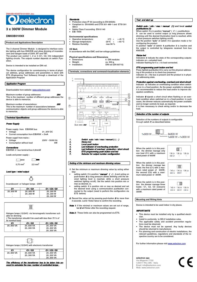
AD84A02KNX module includes 4 digital inputs to interface free
potential contacts; 4 analog / digital inputs for free potential con-
tacts or temperature sensors and 4 led outputs.
Digital inputs can interface sensors, traditional buttons, etc; 4 led
output channels at low voltage can drive LED for synoptics panels
or switches.
Inputs 5 ÷ 8, set as analog inputs, can enable up to 2 temperature
probes (with On/Off threshold) and 2 thermostats to control hea-
ting and cooling equipments, valves, 2 and 4 pipes fan coils; etc..
The device is equipped with appropriate communication interface
with the bus type TP1 (twisted pair) KNX European standard, ac-
cording CEI EN 50090.
Scaricabile dal sito: www.eelectron.com
Numero massimo indirizzi di gruppo: 50
Corrisponde al numero massimo di indirizzi di gruppo diversi che
il dispositivo è in grado di memorizzare.
Numero massimo associazioni: 63
Corrisponde al numero massimo di associazioni tra oggetti di
comunicazione e indirizzi di gruppo che il dispositivo può me-
morizzare.
Attenzione: esiste un limite al numero di associazioni che si
possono creare, sullo stesso dispositivo, tra oggetti di comuni-
cazione in trasmissione (per esempio gli ingressi) e in ricezione
(per esempio le uscite).
Qualora si voglia associare un indirizzo di gruppo usato su un
oggetto di comunicazione in trasmissione (un ingresso), ad un
oggetto di comunicazione in ricezione (una uscita) che ha già
un indirizzo di gruppo precedentemente associato si ricorda che
è possibile aggiungere un massimo di 13 indirizzi di gruppo di
questo tipo sull’intero dispositivo.
Downloadable from website: www.eelectron.com
Maximum number of group addresses: 50
This is the maximum number of different group addresses the de-
vice is able to memorize.
Maximum number of associations: 63
This is the maximum number of associations between commu-
nication objects and group addresses the device is able to me-
morize.
Caution: there is a limit to the number of associations that can be
created, on the same device, between transmission communica-
tions objects (i.e. output feedback) and receiving communication
objects (i.e. outputs).
If you want, on the same device, add a group address linked to
a transmission communication object (feedback) to a receiving
communication object (output) which already has a different group
address associated, please note that you can add a maximum of
13 group addresses of this kind for the whole device.
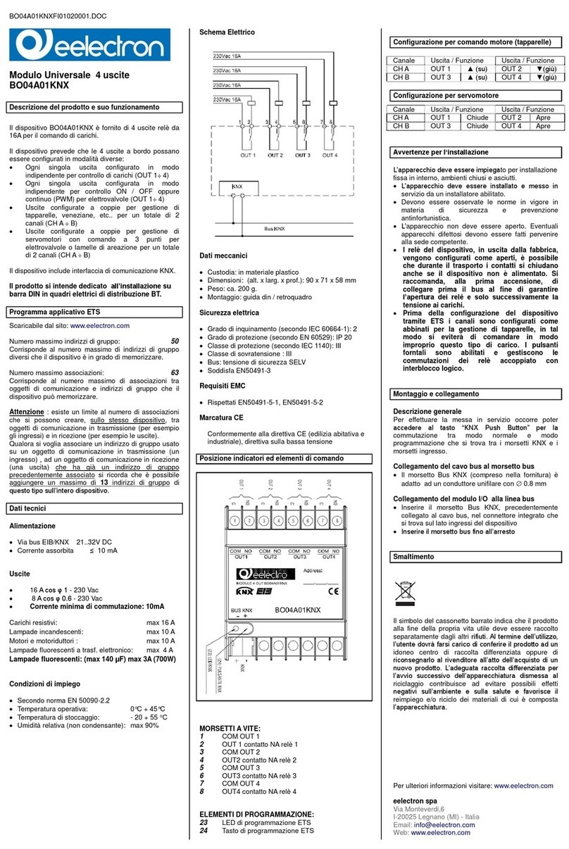
Alimentazione
Attraverso il cavo EIB/KNX
• Tensione 21..30V DC
• Corrente assorbita ≤ 10 mA
IngressiDigitali1-2-3-4
• Per contatti liberi da potenziale (contatti puliti)
• Max lunghezza cavi: ≤ 30 m (cavo intrecciato)
• Tensione di scansione: 3,3 V DC (generata internamente)
• Cablaggio con cavi AWG24 lunghezza 180 mm.
IngressiDigitali5-6-7-8
• Per contatti liberi da potenziale (contatti puliti)
• Max lunghezza cavi: ≤ 10 m (cavo intrecciato)
• Tensione di scansione: 3,3 V DC (generata internamente)
• Connessione tramite morsetto a vite 6 poli.
IngressoAnalogico5-6-7-8
• Collegabili a sonde NTC eelectron codice:
• TS01A01ACC (Intervallo misura -20°C / +100°C)
• TS01B01ACC (Intervallo misura -50°C / +60°C)
• Max lunghezza cavi: ≤ 20 m (cavo intrecciato)
• Connessione tramite morsetto a vite 6 poli.
Uscite Digitali per Led 9 - 10 - 11 - 12
• 4 outputs digitali per pilotaggio led – Max 0,3 mA
• Per led eelectron cod. LD00A01ACC o LD00A11ACC
• Cablaggio con cavi AWG24 lunghezza 180 mm
Elementi di comando
• Pulsante e led EIB/KNX
Dati meccanici
• Custodia: in materiale plastico/nylon
• Classe di protezione: II secondo la EN 61140
• Dimensioni: (alt. x larg. x prof.): 43 x 36 x 24 mm
• Peso: ca. 35 g.
Sicurezza elettrica
• Grado di inquinamento (secondo IEC 60664-1): 2
• Grado di protezione (secondo EN 60529): IP 20
• Classe di protezione (secondo IEC 1140): III
• Classe di sovratensione (secondo IEC 664-1): III
• Bus: tensione di sicurezza SELV DC 21..31 V DC
Power Supply
Via bus EIB/KNX cable
• Voltage 21..32V DC
• Current consumption EIB/KNX ≤ 10 mA
DigitalInput1-2-3-4
• For free potential contacts (dry contacts)
• Max. length of Connecting Cable: ≤ 30 m (twisted cable)
• Voltage Scanning: 3,3 V DC (internally Generated)
• AWG24 cables with 180 mm length
DigitalInput5-6-7-8
• For free potential contacts (dry contacts)
• Max. length of Connecting Cable: ≤ 10 m (twisted cable)
• Voltage Scanning: 3,3 V DC (internally Generated)
• 6 poles terminal with screws.
AnalogInput5–6–7-8
• For NTC temperature probe eelectron code:
• TS01A01ACC (range from -20°C to +100°C)
• TS01B01ACC (range from -50°C to +60°C)
• Max. length of Connecting Cable: ≤ 20 m (twisted cable)
• 6 poles terminal with screws.
Digital Led Output 9 – 10 – 11 -12
• 4 outputs for drive led – Max 0,3 mA
• For LED eelectron code LD00A01ACC or LD00A11ACC
• AWG24 cables with 180 mm length
Control Elements
• EIB/KNX Red LED and button
Mechanical Data
• Case: plastic/nylon
• Protection class: II in accordance with EN 61140
• Dimensions: (width x height. X depth.): 43 x 36 x 24 mm
• Weight: approx. 35 g
Electrical Safety
• Degree of pollution (IEC 60664-1): 2
• Degree of protection (EN 60529): IP 20
• Protection class (according to IEC 1140): III
• Overvoltage class (according to IEC 664-1): III
• Bus: tensione di sicurezza SELV DC 21..31 V DC
Modulo8Ingressi/4UsciteLED
AD84A02KNX
Inwall8Input/4LedOutputModule
AD84A02KNX
Descrizione del prodotto e suo funzionamento Product and Applications description
Programma applicativo ETS
Dati tecnici
ETS Application Program
Technical data
ENIT Rev. 2.0
TS01A01ACC
Attenzione: Mantenere 6 mm di distanza da cavi in tensione!
Warning: keep at least 6 mm from all live parts
Sonde di temperatura
Temperature probes
Tolleranza della resistenza NTC
NTC resistance tolerance ± 3%
Intervallo di misura
Measure range -20°C ÷ +100°C
Cavo
Cable
2 li singolo isolamento
2 wire single insulation
Colore dei cavi
Cable colour
Nero
Black
Colore NTC
NTC colour
Nero
Black
500 ± 20
6 ± 1.5 15 max.
Twin wire AWS26
PVC insulation
Epoxy resin
Ø D2
Twin wire AWS26 double
PVC insulation
Epoxy resin closed in ABS
plastic cap
TS01B01ACC
Attenzione: Mantenere 3 mm di distanza da cavi in tensione!
Warning: keep at least 3 mm from all live parts
D1 = 9mm D2 = 4 mm L1 = 1250mm L2 = 49 mm
Tolleranza della resistenza NTC
NTC resistance tolerance ± 2%
Intervallo di misura
Measure range -50°C ÷ +60°C
Cavo
Cable
2 li doppio isolamento
2 wire double insulation
Colore dei cavi
Cable colour
Bianco
White
Colore NTC
NTC colour
Bianco
White

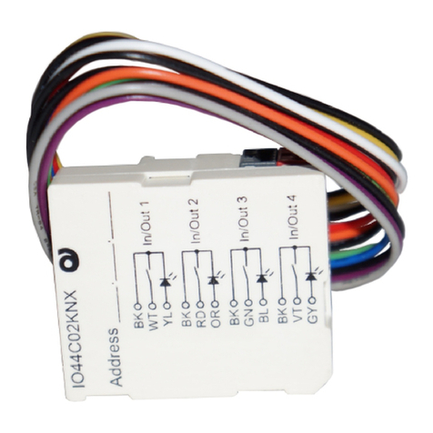
CONNETTORECABLATO(perlaconnessionedegliingressi):
1. NERO Comune IN/OUT
2. BIANCO IN 1
3. GIALLO OUT 1
4. NERO Comune IN/OUT 2
5. ROSSO IN 2
6. ARANCIO OUT 2
7. NERO Comune IN/OUT 3
8. VERDE IN 3
9. BLU OUT 3
10. NERO Comune IN/OUT 4
11. VIOLA IN 4
12. GRIGIO OUT 4
13. - IN / Sonda temperatura 5
14. - IN / Sonda temperatura 6
15. - Comune 5-6
16. - IN / Sonda temperatura 7
17. - IN / Sonda temperatura 8
18. - Comune 7-8
19. - Tasto di programmazione ETS
20. - LED di programmazione ETS
21. Terminale di connessione bus (a innesto):
- polo negativo NERO
+ polo positivo ROSSO
WIREDCONNECOTRS:
1. BLACK Common IN/OUT 1
2. WHITE IN 1
3. YELLOW OUT 1
4. BLACK Common IN/OUT 2
5. RED IN 2
6. ORANGE OUT 2
7. BLACK Common IN/OUT 3
8. GREEN IN 3
9. BLUE OUT 3
10. BLACK Common IN/OUT 4
11. VIOLET IN 4
12. GREY OUT 4
13. - IN / Temperature sensor 5
14. - IN / Temperature sensor 6
15. - Common 5-6
16. - IN / Temperature sensor 7
17. - IN / Temperature sensor 8
18. - Common 7-8
19. - ETS Programming switch
20. - ETS Programming LED
21. - EIB/KNX Connector
- BLACK Bus Negative
+ RED Bus Positive
General Description
The device conguration (KNX physical address assimnment) is
done by pressing the programming push button. Please take care
during installation to leave connection wires long enough in order
to remove the device easily from the wall box for commissioning.
Connecting bus cables
• Connect each single KNX/EIB bus core inside the terminal
block observing bus polarity .
• Slip the bus connection block into the guide slot placed on
the back side of this device and press the block down to the
stop
IMPORTANTE WARNING
• Il dispositivo deve essere installato mantenendo una
distanzaminimadi 4mmtralelinee intensionenon
SELV (230V )eicavi collegati agliingressioal bus
EIB/KNX.
• Il dispositivo non deve essere collegato a cavi in tensione
e mai ad una linea a 230 V.
• L’apparecchio deve essere installato e messo in servizio
da un installatore abilitato.
• Devono essere osservate le norme in vigore in materia di
si-curezza e prevenzione antinfortunistica.
• L’apparecchio non deve essere aperto. Eventuali appa-
recchi difettosi devono essere fatti pervenire alla sede
competente.
L’apparecchio deve essere impiegato per installazione in am-
bienti chiusi e asciutti.
The device may be used for permanent indoor installations in
dry locations within wall box mounts.
Descrizione generale
Per effettuare la messa in servizio occorre poter accedere al ta-
sto “EIB/KNX” per la commutazione tra modo normale e modo
programmazione che si trova tra i morsetti EIB e i morsetti in-
gresso.
Collegamento del cavo bus al morsetto bus
• Il morsetto Bus EIB (compreso nella fornitura) è adatto ad
un conduttore unilare con Ø 0.8 mm
Collegamento del modulo I/O alla linea bus
• Inserire il morsetto Bus EIB/KNX, precedentemente
collegato al cavo bus, nel connettore maschio
dell’accoppiatore bus integrato che si trova sul lato
ingressi del dispositivo
• Inserire il morsetto bus no all’arresto
• Device must be installed keeping a minimum distance
of4mmbetween electricalpowerline (mains)andin-
put cables or red / black bus cable .
• The device must not be connected to 230V cables.
• The prevailing safety rules must be heeded.
• The device must be mounted and commissioned by an
authorised installer.
• The applicable safety and accident prevention regulations
must be observed.
• The device must not be opened. Any faulty devices should
be returned to manufacturer.
• For planning and construction of electric installations, the
relevant guidelines, regulations and standards of the re-
spective country are to be considered.
Posizione indicatori ed elementi di comando
Avvertenze per l’installazione
Montaggio e collegamento
Indicators and Control Elements
Mounting and wiring hints
Installation Instructions
ENIT
eelectron spa
Via Monteverdi 6
I-20025 Legnano (MI) - Italia
Tel: +39 0331 500802 Fax: +39 0331 564826
Email: [email protected] Web: www.eelectron.com
SMALTIMENTO
The crossed-out bin symbol on the equipment or packaging means the product
must not be included with other general waste at the end of its working life.
The user must take the worn product to a sorted waste centre, or return it to the
retailer when purchasing a new one. An efcient sorted waste collection for the
environmentally friendly disposal of the used device, or its subsequent recycling,
helps avoid the potential negative effects on the environment and people’s
health, and encourages the re-use and/or recycling of the construction materials.
DISPOSAL
• Soddisfa EN 50090 e IEC 664-1: 1992
Requisiti EMC
• Rispettati EN 50081-1, EN 50082-2 e EN 50090-2.2
Condizioni di impiego
• Secondo norma EN 50090-2.2
• Temperatura ambiente durante il funzionamento: 0°C + 45°C
• Temperatura di stoccaggio: - 20 °C + 55 °C
• Umidità relativa: max 90 %
Marcatura CE
Conformemente alla direttiva CE (edilizia abitativa e industria-
le), direttiva sulla bassa tensione.
43 24
NERO / BLACK
BIANCO / WHITE
GIALLO/ YELLOW
ROSSO / RED
ARANCIO/ ORANGE
NERO/ BLACK
VERDE / GREEN
BLU/ BLUE
VIOLA / VIOLET
GRIGIO/ GREY
NERO/ BLACK
NERO / BLACK
1
2
3
4
5
6
7
8
9
10
19
20
13
14
15
16
17
18
21
11
12
BUS KNX
KNX
COM
COM
COM
IN/TS 5 13
1
2
3
4
5
6
7
8
9
10
11
12
14
15
16
17
18
IN/TS 8
IN/TS 7
IN/TS 6
IN
OUT
COM
IN
OUT
COM
IN
OUT
COM
IN
OUT
• Meets EN 50090 and IEC 664-1: 1992
EMC Requirements
• Complied with EN 50081-1, EN 50082-2 and EN 50090-2.2
Terms of use
• According to EN 50090-2.2
• Ambient temperature during operation: 0 °C + 45 °C
• Storage temperature: - 20 °C + 55 °C
• Relative humidity: max 90%
CE Mark
According to EMC guideline and low voltage directive
Il simbolo del cassonetto barrato indica che il prodotto alla ne della propria vita
utile deve essere raccolto separatamente dagli altri riuti. AI termine dell’utilizzo,
l’utente dovrà farsi carico di conferire il prodotto ad un idoneo centro di raccolta
differenziata oppure di riconsegnarlo al rivenditore all’atto dell’acquisto di
un nuovo prodotto. L’adeguata raccolta differenziata per l’avvio successivo
dell’apparecchiatura dimessa al riciclaggio contribuisce ad evitare possibili
effetti negativi sull’ambiente e sulla salute e favorisce il reimpiego e/o riciclo dei
materiali di cui e composta l’apparecchiatura.
Other Eelectron Control Unit manuals
Popular Control Unit manuals by other brands

Viessmann
Viessmann vitotronic 200-h Installation and service instructions
PEP Modular Computers
PEP Modular Computers V1553B user manual
Allen-Bradley
Allen-Bradley 1747-DTAM-E user manual
LEGRAND
LEGRAND 4 121 73 quick start guide
MICROENER
MICROENER MX14-5 Operation manual
Eaton
Eaton SmartWire-DT SWD Series manual
THORLABS
THORLABS ECL1525M-PM Operation manual
AUDAC
AUDAC NMP40 user manual

HORNER
HORNER VIM400 Product Specifications and Installation Data
FireAngel
FireAngel ZW-MODULE Installation guides

AB Quality
AB Quality 1756-ENBT ControlLogix installation instructions
Azbil
Azbil ACTIVAL Intelligent Component Series Specifications & instructions
