manuals.online logo
Brands
  1. Home
  2. •
  3. Brands
  4. •
  5. WABCO
  6. •
  7. Control Unit
  8. •
  9. WABCO MICO ACV-SMO Operating instructions

WABCO MICO ACV-SMO Operating instructions

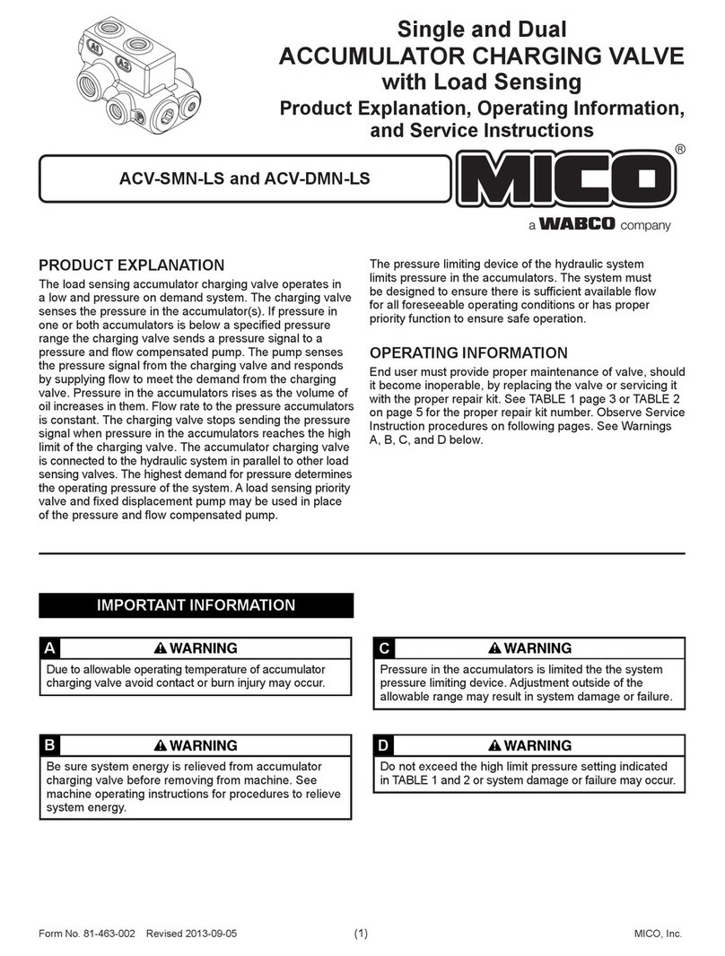
SINGLE ACCUMULATOR
CHARGING VALVE
Product Explanation,
Operating Information,
and Service Instructions
PRODUCT EXPLANATION
The accumulator charging valve is designed for installation
in an open center hydraulic system between the pump and
the downstream secondary hydraulic devices.
The accumulator charging valve supplies oil on demand to
the accumulator from the open center circuit. Accumulator
charging is accomplished at a preset rate (GPM) and is
relatively constant within the preset pressure limits.
The ow to the downstream secondary hydraulic devices
will be reduced fractionally for a short time when the
accumulator is charging. This does not noticeably affect
operation of these components. Full system pressure is
available to the downstream secondary hydraulic devices
at all times provided oil delivery and pressure from the
pump is not impeded.
This accumulator charging valve does not limit pressure
in the accumulator that is from system load downstream
of the ow through port. Over pressure protection is to be
located between the pump and accumulator charging valve.
OPERATING INFORMATION
End user must provide proper maintenance of valve,
should it become inoperable, by replacing the valve or
servicing it with the proper repair kit. See TABLE 1 on
page 3 for the proper repair kit number. Observe Service
Instruction procedures on following pages. See Warnings
A, B, and C below.
IMPORTANT INFORMATION
Due to allowable operating temperature of accumulator
charging valve avoid contact or burn injury may occur.
A
Be sure system energy is relieved from accumulator
charging valve before removing from machine. See
machine operating instructions for procedures to relieve
system energy.
B
Do not exceed the high limit pressure setting indicated in
TABLE 1 or system damage or failure may occur.
C
ACV-SMO
This document is intended to provide general information about MICO Products. MICO, Inc. has attempted to present accurate information about MICO Products
in its catalogs, brochures, and other printed materials. MICO, Inc. is not responsible for errors, inaccuracies, or inconsistencies that may exist in any catalog,
brochure, or other printed materials or any damages arising from or related to reliance on information in them. Materials and specications for MICO Products set
forth in catalogs, brochures, and other printed materials are subject to change without notice or obligation. Refer to www.mico.com for the most recent versions of
our literature. If you have any questions concerning MICO Products, please contact MICO, Inc. All MICO Products and service are sold and provided subject to the
MICO Warranty at www.mico.com in effect on the date of sale or supply.
MICO is a trademark and registered trademark of MICO, Inc. MICO is registered in the U.S. Patent and Trademark Ofce as well as in Australia, Canada, Indonesia, Japan, Peoples Republic of China, South Korea, and the European Community.
MICO, Inc.
1911 Lee Boulevard / North Mankato, MN U.S.A. 56003-2507
Tel: +1 507 625 6426 Fax: +1 507 625 3212
Form No. 81-463-008 Revised 2010-11-08 www.mico.com
MICO, Inc. (2) Form No. 81-463-008 Revised 2010-11-08
SERVICE INSTRUCTIONS
Disassembly
(Refer to Figure 1)
1. Remove plug (1) from housing (7). Remove o-ring (2) from
plug (1). NOTE: Plug (1) is under spring tension.
2. Remove spring (3) and rod (4) from housing (7).
3. Remove plug (8) from housing (7). Remove o-ring (2) from
plug (8).
4. Remove spool (6) from housing (7) through plug (1) end ONLY.
Remove quad ring (5) from spool (6).
5. Earlier design: Loosen nut (9) on screw assembly (11) and
remove screw assembly (11) from housing (7). Remove o-ring
(10) from screw assembly (11). Remove spring (12), steel ball
(13), seat (14), and o-ring (15) from housing (7).
Later design: Some later designs use a directional spring
(12). Directional spring (12) is attached to screw assembly
(11) by means of the small diameter end of spring (12)
being snapped into a groove on the nose end of screw
assembly (11). See Figure 1c. Remove nut (9) and remove
screw assembly (11) from housing (7). Remove o-ring (10)
from screw assembly (11) from nut (9) side of screw assembly.
Remove shim (31), spring (12), steel ball (13), seat (14), o-ring
(15), and washer (32) from housing (7).
6. Thread a 3/8-16UNC cap screw into washer (16) and remove
washer (16) from housing (7).
7. Remove plug (29) from housing (7). Remove o-ring (15) from
plug (29).
8. BEFORE moving screw (28), ACCURATELY MEASURE ITS
DEPTH from the end of housing (7) and record for reassembly
purposes. Remove screw (28) from housing (7).
9. Remove spring (27), retainer (26), and ball (25). Be sure to
keep ball (25) separate from ball (20) for reassembling.
10. Remove pin (30) from screw (28) using a drive pin punch.
NOTE: Be careful not to damage threads.
11. Remove plug (17) from housing (7). Remove o-ring (15) from
plug (17). NOTE: Be careful not to damage threads.
12. Remove spring (18), stop (19), and ball (20) from housing (7).
13. Place housing (7) on bench with plug (17) end down. Spool (21)
may or may not fall out at this point.
14. Using a 6.3-7.9 mm (0.25-0.31 in) diameter wood or plastic
dowel, carefully remove insert (22) and spool (21) from housing
(7). Insert (22) must come out plug (17) end of housing (7). Be
careful not to scratch or mar valve seats on insert (22).
15. Remove spool (21) from insert (22). Remove o-rings (23 & 24)
from insert (22).
Assembly
(Refer to Figure 1)
WASH ALL PARTS WITH CLEAN SOLVENT AND DRY. LUBRICATE
ALL RUBBER PARTS WITH CLEAN SYSTEM FLUID PRIOR TO
ASSEMBLY. BE SURE ENTIRE ASSEMBLY PROCEDURE IS
DONE USING CONTAMINATION FREE METHODS.
1. Install new o-ring (2) on plug (8). Install plug (8) into housing (7)
and torque 122.0-135.6 N∙m (90-100 lb∙ft).
2. Install new quad ring (5) on spool (6). Be sure quad ring (5)
does not twist in groove.
3. Lubricate spool (6) with clean system uid and insert into
housing (7) as shown in Figure 1.
4. Install spring (3) and rod (4) into housing (7).
5. Install new o-ring (2) on plug (1). Install plug (1) into housing (7)
and torque 122.0-135.6 N∙m (90-100 lb∙ft).
6. Install new o-rings (23 & 24) on insert (22) and install insert (22)
into housing (7). Note direction of assembly. Seat insert (22)
using a 12.7 mm (0.50 in) diameter wood or plastic dowel.
7. Install spool (21) into insert (22) in housing (7). Note direction
of spool (21), long shoulder end is up toward end plug (17),
see Figure 1a.
8. Install ball (20) on insert (22) in housing (7). Install stop (19)
over ball (20) and spring (18) over stop (19).
9. Install new o-ring (15) on plug (17) and carefully install into
housing (7), centering spring (18). Torque plug (17) 47.5-54.2 N∙m
(35-40 lb∙ft).
10. Turn housing (7) so plug (8) is vertically upward. Install ball (25)
in housing (7). Be sure ball (25) is centered in bottom of hole.
Install retainer (26) and spring (27) into housing (7).
11. Insert new pin (30) in screw (28). Be sure pin (30) is aligned
properly and is evenly driven into screw (28). NOTE: Be careful
not to damage threads.
12. Thread screw (28) in housing (7) to the depth recorded during
disassembly.
13. Install new o-ring (15) on plug (29). Install plug (29) in housing
(7) and torque 47.5-54.2 N∙m (35-40 lb∙ft).
14. Install washer (16) in housing (7). Note direction of washer (16),
see Figure 1b.
15. Earlier Design: Install new o-ring (10) on screw assembly (11).
Install o-ring (15), seat (14), steel ball (13), spring (12), and
screw assembly (11) into housing (7). Torque screw assembly
24.4-29.8 N∙m (18-22 lb∙ft). Then install nut (9) on screw
assembly (11) and torque nut 43.4-51.5 N∙m (32-38 lb∙ft).
Later Design: Some later designs use a directional spring
(12). Directional spring (12) is attached to screw assembly
(11) by means of the small diameter end of spring (12)
being snapped into a groove on the nose end of screw
assembly (11). If necessary, reattach the small diameter of
spring (12) into the groove on the nose end of screw
assembly (11) using a slight twisting motion. See Figure 1b.
Install new o-ring (10) on screw assembly (11) from nut (9) side
of screw assembly. Install washer (32), new o-ring (15), seat (14),
steel ball (13), and spring (12) in housing (7). Fully lubricate
shim (31) with clean system uid and install in housing (7) on
end of seat (14). Install screw assembly (11) in housing (7).
Torque screw assembly (11) 24.4-29.8 N∙m (18-22 lb∙ft). Then
install nut (9) on screw assembly (11) and torque nut 43.4-51.5 N∙m
(32-38 lb∙ft).
VALVE ADJUSTMENT
(Refer to Table 1)
1. See machine servicing instructions to properly reinstall the
accumulator charging valve. Tee an accurate pressure gauge
on an accumulator line.
2. Start pump and allow approximately one minute for charging to
start (pressure in gauge will read accumulator precharge plus).
If valve does not begin to charge, stop the pump and remove end
plug (29) and turn screw (28) approximately 1/4 turn clockwise
Reinstall end plug (29). Check the high limit specications
(see TABLE 1). Repeat adjustment of screw (28) as needed
until the high limit setting is met. Pressure limits can be checked
correctly only if after each adjustment of screw (28) the
accumulator pressure is reduced below the low limit setting
and the system recharges the accumulator pressure to its
high limit. NOTE: Be sure to reinstall plug (29) before
starting pump.
3. Torque end plug (29) 47.5-54.2 N∙m (35-40 lb∙ft).
Be sure system energy is relieved from accumulator charge
valve before removing from machine. See machine service
manual for procedures to relieve system energy.
NOTE
Locate the model number on the accumulator charging valve and
compare it to the model number in TABLE 1. Be sure you have the
proper service instructions.
NOTE
Observe torque specications as indicated in assembly procedures
or system damage or failure may occur.
Do not exceed the high limit pressure setting indicated in
TABLE 1 or system damage or failure may occur.
Form No. 81-463-008 Revised 2010-11-08 (3) MICO, Inc.
TABLE 1 (Specications)
Model
Number
Repair Kit
Number
Nominal
High Limit (cut out)
Nominal
Low Limit (cut in)
bar (PSI) bar (PSI)
06-463-046
06-463-062
06-400-147
06-400-147
189.6 ± 3.5 (2750 ± 50)
186.2 ± 3.5 (2700 ± 50)
144.8 ± 3.5 (2100 ± 50)
155.1 ± 1.7 (2250 ± 25)
NOTE: If your product number is not listed, please contact MICO, Inc. for information.
 Items included in Repair Kit
FIGURE 1
Figure 1a
Figure 1c
Figure 1b
MICO, Inc. (4) Form No. 81-463-008 Revised 2010-11-08
SERVICE CHECKS FOR HYDRAULIC SYSTEMS
ACCUMULATOR CHARGING CYCLE
REPEATS FREQUENTLY WHEN
ACCUMULATOR IS NOT NORMALLY
BEING DISCHARGED IN SERVICE
1. Leaking accumulator lines or ttings
1. Check lines and ttings for leaks
and correct
2. Incorrect setting of accumulator
gas charge
2. Check accumulator gas charge
3. Line to accumulator plugged
3. Replace line
4. Inoperative charging valve
4. Replace charging valve
ACCUMULATOR STARTS TO CHARGE
BUT DOES NOT REACH HIGH LIMIT
1. No oil or low oil level in tank
1. Check oil level
2. Pump worn or inoperative and not
delivering full ow or pressure
2. Check pump
3. Inoperative system relief valve (valve
leaking or has low setting so full ow
and pressure are not available)
3. Check relief valve
4. Inoperative charging valve
4. Replace charging valve
ACCUMULATOR CHARGING TIME
TOO LONG
1. No oil or low oil level in tank
1. Check oil level
2. Relief valve setting too low
2. Check valve setting
3. Pump worn or inoperative and not
delivering full ow or pressure
3. Check pump
4. Inoperative charging valve
4. Replace charging valve
ACCUMULATOR FAILS TO
START CHARGING
1. No oil or low oil level in tank
1. Check oil level
2. Worn or defective pump
2. Check pump pressure and ow
3. Inoperative relief valve
3. Check relief valve setting
4. Air in accumulator line
4. Bleed accumulator line
5. Inoperative charging valve
5. Replace charging valve
VERY RAPID CYCLING OF
CHARGING VALVE
1. Incorrect setting of accumulator
gas charge
1. Check accumulator gas charge
2. Inoperative charging valve
2. Replace charging valve
LACK OF ADEQUATE FLOW
THROUGH VALVE
1. Inoperative pump
1. Check pump pressure and delivery
2. Inoperative relief valve
2. Check relief valve setting
3. Blocked lines
3. Replace lines
4. Inoperative charging valve
4. Replace charging valve
SERVICE DIAGNOSIS
ACCUMULATOR CHARGING CYCLE
REPEATS FREQUENTLY WHEN
ACCUMULATOR IS NOT NORMALLY
BEING DISCHARGED IN SERVICE
1. Steel ball (13) leaking.
2. O-ring (15) next to seat (14)
leaking.
3. O-ring (23) leaking.
4. Ball (20) leaking.
5. Inoperative seat on insert (21).
ACCUMULATOR STARTS TO CHARGE
BUT DOES NOT REACH HIGH LIMIT
1. O-ring (24) leaking.
2. Quad ring (5) on spool (6) has been
damaged or worn.
ACCUMULATOR CHARGING TIME
TOO LONG
1. Steel ball (13) stuck, partially closed
2. Seat (14) partially plugged
ACCUMULATOR FAILS TO
START CHARGING
1. Broken spring (27).
2. Broken spring (3).
3. O-ring (2) damaged.
4. Spool (6) stuck.
VERY RAPID CYCLING OF
CHARGING VALVE
1. Insert (22) worn.

Other WABCO Control Unit manuals

WABCO MICO ACV-DMN-LS Operating instructions

WABCO

WABCO MICO ACV-DMN-LS Operating instructions

WABCO 461 317 User manual

WABCO

WABCO 461 317 User manual

WABCO 461 307 User manual

WABCO

WABCO 461 307 User manual

WABCO ABDX Operating instructions

WABCO

WABCO ABDX Operating instructions

WABCO TP0223 Service manual

WABCO

WABCO TP0223 Service manual

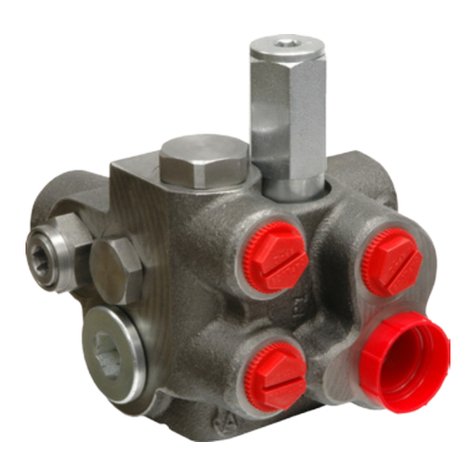
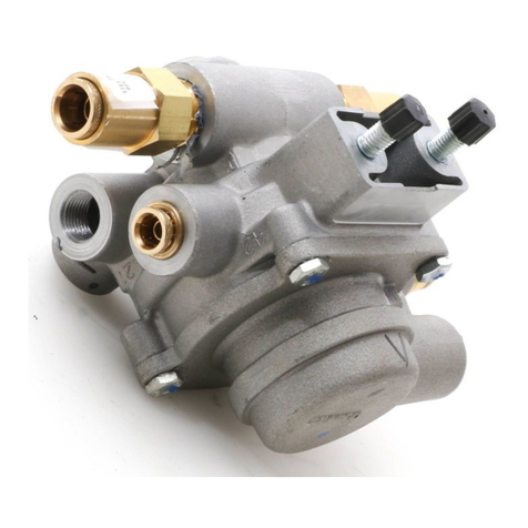
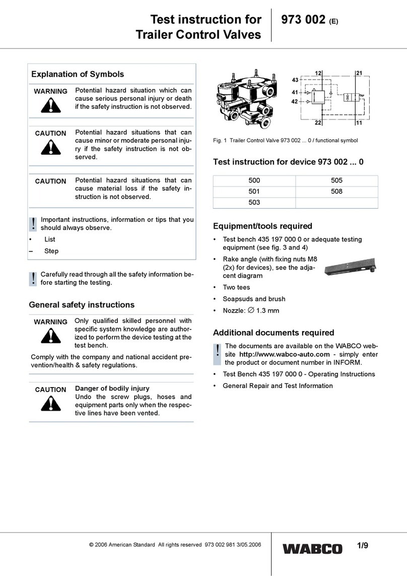
WABCO 973 002 User manual

WABCO

WABCO 973 002 User manual

WABCO MICO ACV-DMO-RV Operating instructions

WABCO

WABCO MICO ACV-DMO-RV Operating instructions

WABCO MICO 20-100-597 Operating instructions

WABCO

WABCO MICO 20-100-597 Operating instructions

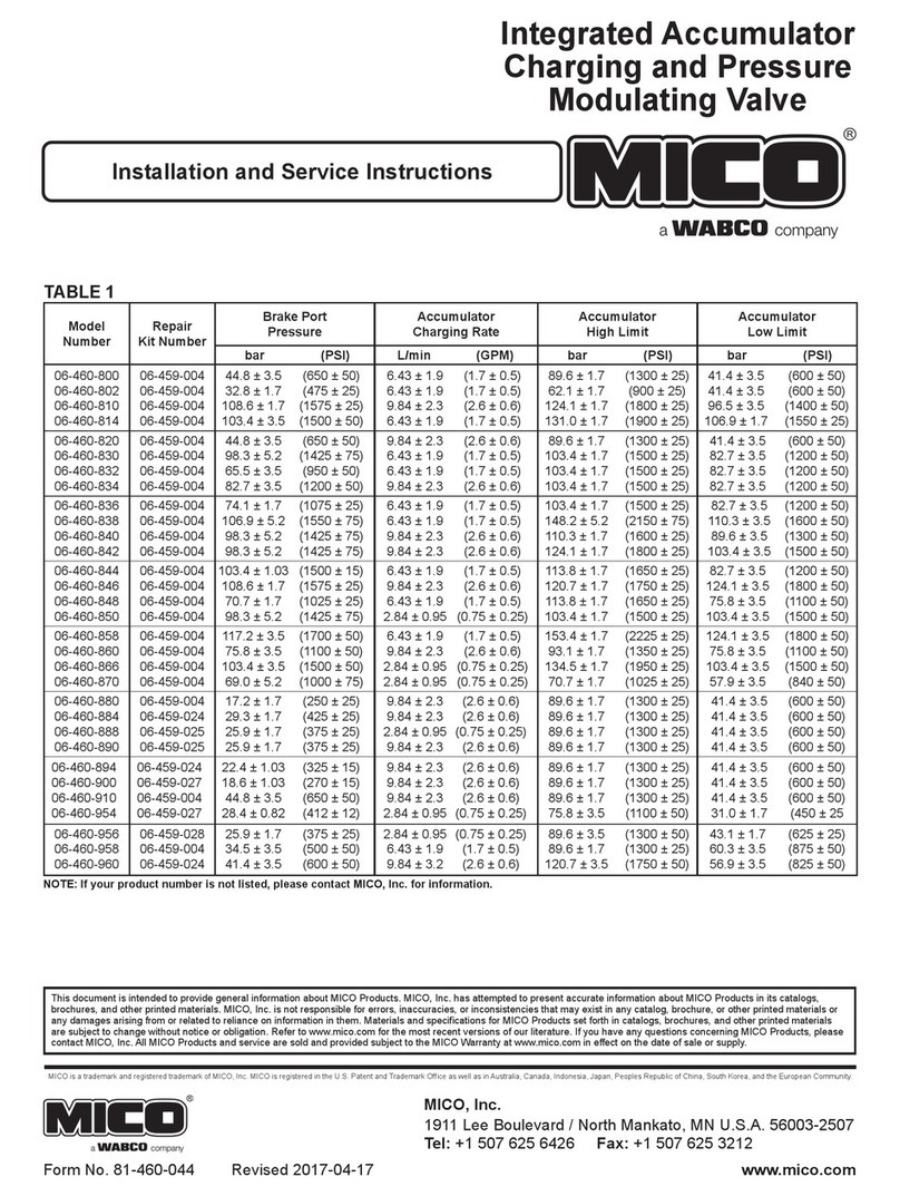
WABCO MICO 06-460-800 Quick guide

WABCO

WABCO MICO 06-460-800 Quick guide

WABCO MICO ACV-SMO Operating instructions

WABCO

WABCO MICO ACV-SMO Operating instructions

WABCO IR-2 Service manual

WABCO

WABCO IR-2 Service manual

Popular Control Unit manuals by other brands

Texas Instruments ADS5296 user guide

Texas Instruments

Texas Instruments ADS5296 user guide

A.R.I. D-070-P Installation operation & maintenance

A.R.I.

A.R.I. D-070-P Installation operation & maintenance

Advantech IPMI-2000 Startup manual

Advantech

Advantech IPMI-2000 Startup manual

PRASTEL M1000E quick start guide

PRASTEL

PRASTEL M1000E quick start guide

REXROTH IndraControl L25 operating instructions

REXROTH

REXROTH IndraControl L25 operating instructions

Tempo Fitness 521E instruction manual

Tempo Fitness

Tempo Fitness 521E instruction manual

GEA VP8002 Operation Manual/Installation Instructions/Parts List

GEA

GEA VP8002 Operation Manual/Installation Instructions/Parts List

Satel ETHM-1 Plus manual

Satel

Satel ETHM-1 Plus manual

Siemens SINAMICS DCM List manual

Siemens

Siemens SINAMICS DCM List manual

lancer STANDARD LEVER Operation manual

lancer

lancer STANDARD LEVER Operation manual

Wigersma & Sikkema UNIGAS 300 Installation, operating and maintenance manual

Wigersma & Sikkema

Wigersma & Sikkema UNIGAS 300 Installation, operating and maintenance manual

Raytheon Anschütz Standard 22 GYRO COMPASS Operator's and service manual

Raytheon Anschütz

Raytheon Anschütz Standard 22 GYRO COMPASS Operator's and service manual

ICP DAS USA ET-7H16M Series user manual

ICP DAS USA

ICP DAS USA ET-7H16M Series user manual

Channel Actulux SVM 24V-5A quick start guide

Channel

Channel Actulux SVM 24V-5A quick start guide

Burkert 6126 operating instructions

Burkert

Burkert 6126 operating instructions

GAMMA SYSTEM GP02R quick start guide

GAMMA SYSTEM

GAMMA SYSTEM GP02R quick start guide

Texas Instruments TPS2398EBM user guide

Texas Instruments

Texas Instruments TPS2398EBM user guide

Beninca CP.B24ESA manual

Beninca

Beninca CP.B24ESA manual

manuals.online logo
manuals.online logoBrands
  • About & Mission
  • Contact us
  • Privacy Policy
  • Terms and Conditions

Copyright 2025 Manuals.Online. All Rights Reserved.