P.A. VRP200 User manual

Last Update: 30/01/17
1
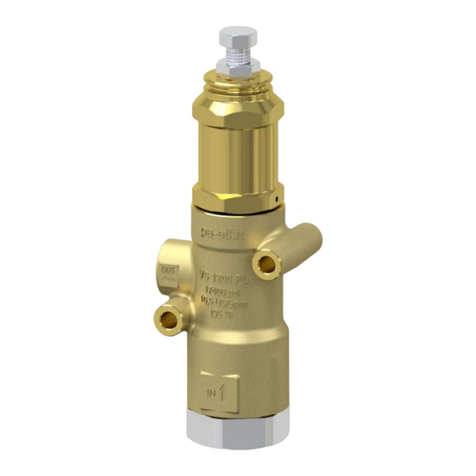
VRP200 –Safety and pressure regulating valve
Technical manual: E 205
Compensated pressure regulating valve with double connection for inlet port.
Regulates the bypass of the fluid with a minimum variation of the pressure.
Suitable to be utilized as a safety valve.
DN 10
60.0220.00 VRP200 G3/8 F
60.0220.60 VRP200 G3/8 F
60.0220.05 VRP200 3/8NPT F
60.0220.65 VRP200 3/8NPT F
- Sturdy construction in Sst and brass.
- Piston return operated by strong springs for steady working
and setting without faltering.
- Multiple connections for quick installation.
- Pressure set up differentiated by choosing between two
springs.
AS A SAFETY VALVE
- Reliable intervention discharging all the flow.
- Prompt and effective damping action against pressure spikes.
AS A PRESSURE REGULATING VALVE
- High balancing to guarantee slight variations of the rated
pressure when the flow varies in bypass.
- Usable with a multiple number of lances.
TECHNICAL SPECIFICATIONS
Max.flow rate 30 l/min (1) - Max. temperature 90°C (2)
Part number
Rated
pressure
bar - MPa
Permissible
pressure
bar - MPa
Minimum
adjustable
pressure
bar - MPa
(3) Pressure increase
as a VS –as a VRP
bar - MPa - bar - MPa
Inlet
Bypass
Weight
g
60.0220.00
100 - 10
120 - 12
10 - 1
28 –2.8 -17 –1.7
G3/8 F
G3/8 F
570
60.0220.60
220 - 22
250 - 25
22 –2.2
33 –3.3 -18 –1.8
G3/8 F
G3/8 F
605
60.0220.05
100 - 10
120 - 12
10 - 1
28 –2.8 -17 –1.7
3/8NPT F
3/8NPT F
570
60.0220.65
220 - 22
250 - 25
22 –2.2
33 - 3.3 -18 –1.8
3/8NPT F
3/8NPT F
605
(1) Max flow rate: 15 l/min if fed by the lower fitting.
(2) The valve has been designed for a continuous use at a water temperature of 60°C. It can resist for short periods at a maximum
temperature of 90°C.
(3 Pressure increase = is the increase of pressure needed into the valve for discharging the max. flow when utilized at rated pressure
Instruction manual, maintenance, installation, spare parts.
For a correct utilization, follow the directions of this manual
Re-print them on the use and maintenance booklet of the machine.
n. 12.9205.00

Last Update: 30/01/17
2
DIMENSIONAL DRAWING.
INSTRUCTIONS
SELECTION
This product is to be utilized with clean fresh water, even slightly additivated with normal detergents. For use involving different or
corrosive liquids, contact the PA Technical department. Choose the valve in line with the data of nominal running (system rated
pressure, max flow and max temperature). In any case, the pressure of the machine should not exceed the permissible pressure rate
imprimed on the valve.The feed through the lower fitting is possible with a reduced flow rate (see point 1). When in use as pressure
regulator, adopt a nozzle that allows a bypass of at least 5% of the total flow, bearing in mind that a worn out nozzle causes pressure
loss. The valve, assembled in line with these indications, avoids pressure spikes whilst the machine is in operation.
INSTALLATION
This accessory, on a system that produces hot water, must be fitted in front of the heat generator.
As a SAFETY VALVE: in the case when frequently combined with unloader valves and low pressure in the pump, it has to be fitted in
the section that remains pressurized when the gun is shut off.
As a PRESSURE REGULATOR: maintains the pressure in the system steady during flow changes. Always install with the correct
specifications when combined with a safety valve. In case of discharge in the tank or directly into the pump, it is necessary to provide
devices capable to prevent damaging turbolence to the liquid flow.
OPERATIONS
The discharge should be returned to a baffled tank. If, on the contrary, the pump is fed directly from the water mains, it is advisable to
install a pressure reducing valve, before the pump, to avoid dangerous pressure spikes which could badly damage manifolds and
suction valves. In case of extended conditions of bypass directed to the suction side of the pump, it is recommended to install a thermal
valve (VT3 or VT6) to avoid dangerous water temperature build-up.
PRESSURE ADJUSTMENT/SETTING
As a SAFETY VALVE: the adjustment has to be made in such a way that the pressure setting is not superior to the system working
pressure and its accessories; this prevents the arisal of numerous pressure increases in hot water systems and static pressure (gun
shut off).
As a PRESSURE REGULATOR: adjust the valve when the system is pressurized and the gun open. The operation will be easy and
smooth if the proper nozzle is chosen. When rotating the adjustment knob, it has to correspond to a consequent pressure increase;
should the pressure stop increasing before reaching the desired value, do not insist, but check the correct nozzle size in relation to
flow and pressure. On reaching the desired pressure, tighten the nut (pos 15) with a drop of paint in order to emphasize any tampering
or slackness.
ATTENTION: The nut (pos 15 nr 1pc) must never be removed otherwise a mechanical safety feature that limits the max pressure
will lack , avoiding serious damage to persons and machine.

Last Update: 30/01/17
3
PROBLEMS AND SOLUTIONS
PROBLEMS
PROBABLE CAUSES
SOLUTIONS
Valve cycles
- Air inside the system
- Worn out seals
- Clogged circuit
- Flush out
- Replace
- Clean or widen passages
The valve does not reach
pressure
- Unproper nozzle size
- Seat/shutter/ball worn out
- Damaged nozzle
- Impurities
- Modify
- Replace
- Replace
- Clean
Pressure drop
- Worn out nozzle
- Pump gaskets worn out
- Valve seat worn out
- Air inside the system
- Replace
- Replace
- Replace
- Flush out
Pressure spikes
- There is not a min.5% of total flow in bypass
- Clogged nozzle
- Re-adjust
- Clean
- Repeat adjustment and replace nozzle
Water leakage from bypass
Valve pounding
- O-ring seat damaged
- Damaged seat
- Impurities or worn out valve pumps
- Replace
- Replace
- Clean
REGULATIONS : see norm manual
The accessory hereby described bears the CE marking in accordance with the Norms and Directives
applied on the Declaration of conformity.
For a correct utilization, follow the directions described in this manual and re-print them on the Use and maintenace manual of the
machine.
Make sure that you are given the Original Conformity Declaration for the accessory chosen. The present manual is valid for all
unloader valves named VRP 200.
MAINTENANCE
Maintenance has to be carried out by Specialized Technicians.
STANDARD: every 400 working hours (circa 10,000 cycles), check and lubricate the seals with water
resistant grease.
SPECIAL: every 800 working hours( circa 20,000 cycles), control the wear of the seals and internal parts and
if necessary, replace with original PA parts taking care during installation and to lubricate with water resistant
grease.
ATTENTION: reassemble the valve in the correct manner paying special attention how to set the valve as
described in the paragraph PRESSURE ADJUSTMENT/SETTING.
The manufacturer is not to be considered responsible for damage as a result from incorrect fitting and
maintenance
Technical data, descriptions and illustrations are indicative and liable to modification without notic

Last updated 14/09/2017
60.0220.00 VRP200 safety valv. 3/8F Bsp-120bar
60.0220.05 VRP200 safety valv. 3/8F Npt-120bar 60.0220.60 VRP200 safety valv. 3/8F Bsp-250bar
60.0220.65 VRP200 safety valv. 3/8F Npt-250bar
Pos. P/N Description Q.ty K1K2K3K4 Pos. P/N Description Q.ty K1K2K3K4
1 60.0024.31 Suction coupl., 3/8F Bsp brass 1 10
1 60.0030.31 Suction coupl., 3/8F Npt brass (1) 1 10
2 10.3068.00 O-ring, 1,78x17,17 mm 2 • 10
3 60.0015.51 Spring, 1,4x10x16 mm Sst. 1 10
4 14.7461.00 Ball, 13/32" Sst. 1 • 10
5 60.0259.20 Seat, 8mm + O-ring, 1,78mm 1 • 10
6 60.0251.35 Housing -VRP200, 3/8F Bsp brass 1 3
6 60.0252.35 Housing -VRP200, 3/8F Npt brass (1) 1 1
7 10.4021.00 Back-up ring, opn. 11,5x15,9x1,2 mm 2 • 10
8 10.3175.00 O-ring, 2,62x10,77 mm 1 • 10
9 60.0061.23 Valve piston, Sst. 1 5
10 10.3170.00 O-ring, 2,62x7,6 mm 1 • 10
11 10.4020.00 Back-up ring, 8x12,6x1,2 mm 1 • 10
12 60.0064.31 Piston holder, brass 1 5
13 15.1021.00 Roll pin, 3x14 mm Sst. 1 10
14 60.0012.61 Spring, 5x25x50 mm white (2) 1 5
14 60.0033.61 Spring, 5,7x26x53 mm blue (3) 1 5
15 11.4576.31 Hex. nut, M8, brass 1 10
16 60.0011.31 Spring holder ring, brass 1 5
17 11.4574.00 Hex. nut, M8 2 10
18 60.0028.31 Plug,brass 3/8 Bsp,hex.19 1 25
18 60.0025.31 Grub screw, brass 3/8M Npt (1) 1 10
19 14.4042.00 Washer, 16,7x22x1,5 mm alu. 1 25
Kit P/N Description
K1 60.0257.24 Spares kit -VRP200, 8x5pcs. 1
(1) 60.0220.65 (2) 60.0220.00 (3) 60.0220.60
Other P.A. Control Unit manuals
Popular Control Unit manuals by other brands

LOXONE
LOXONE Touch Pure Air Series quick start guide

Argo-Hytos
Argo-Hytos PRM7 Series instructions

Genebre
Genebre 2415 Installation, operation and maintenance manual

Omron
Omron CJ1W-TS562 instruction sheet

Cistermiser
Cistermiser Direct Flush Discreet installation guide

ASCO Valves
ASCO Valves 8004 Series Installation & maintenance instructions

Mitsubishi
Mitsubishi Wi-Fi Control installation guide

ABB
ABB LEANtouch 6x36/30M-500 Series product manual

Otto Bock
Otto Bock 4r136 Instructions for use

Agilent Technologies
Agilent Technologies 4890 installation guide

SMC Networks
SMC Networks XGT312-50336 Series Operation manual

Roger
Roger H70/200AC Instruction and warnings for the installer