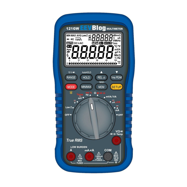
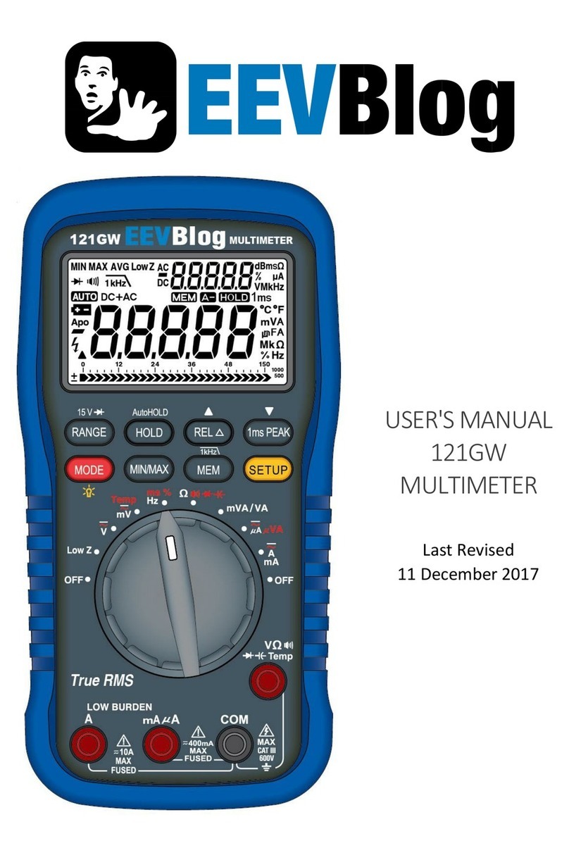
EEVBlog 121GW User manual

121GW Multimeter
User’s Manual
Last Revised 26 October 2018

2
121GW Multimeter User’s Manual 26 Oct 2018
Table of Contents
Contact..................................................................................................7
Glossary of Terms .................................................................................8
Change Log ...........................................................................................9
General................................................................................................10
FCC/IC Information............................................................................................10
Information to the User.....................................................................................10
Introduction.........................................................................................11
Multimeter Features............................................................................12
Summary .............................................................................................................12
Logging Capabilities ..........................................................................................12
Mechanical ..........................................................................................................12
Software...............................................................................................................12
Batteries...............................................................................................................12
Specications......................................................................................13
General .................................................................................................................13
DC & AC Voltage.................................................................................................14
Current..................................................................................................................15
Resistance & Capacitance................................................................................15
Diode.....................................................................................................................15
Frequency & Duty Cycle ....................................................................................16
VA ..........................................................................................................................16
Temperature & Continuity.................................................................................16
Bluetooth..............................................................................................................17
Standards............................................................................................18
Compliance Symbols.........................................................................................18
IEC Standards .....................................................................................................18
ANSI Standards ..................................................................................................18
Safety (EN) ..........................................................................................19
Sécurité (FR) .......................................................................................21

3
121GW Multimeter User’s Manual 26 Oct 2018
Symbols ..............................................................................................23
Meter Overview ...................................................................................24
Front......................................................................................................................24
Back ......................................................................................................................25
Display screen.....................................................................................................26
Rotary switch ......................................................................................................26
Keypad..................................................................................................................27
Input terminals....................................................................................................28
Positions & Modes ..............................................................................29
OFF
LowZ
mVA/VA
Hz
ms
%
VmV
Temp
mA
A
VA
A
Ω
................................................................................................................29
OFF
LowZ
mVA/VA
Hz
ms
%
VmV
Temp
mA
A
VA
A
Ω
.........................................................................................................................29
OFF
LowZ
mVA/VA
Hz
ms
%
VmV
Temp
mA
A
VA
A
Ω
.................................................................................................................29
OFF
LowZ
mVA/VA
Hz
ms
%
VmV
Temp
mA
A
VA
A
Ω
..................................................................................................................30
OFF
LowZ
mVA/VA
Hz
ms
%
VmV
Temp
mA
A
VA
A
Ω
..................................................................................................................30
OFF
LowZ
mVA/VA
Hz
ms
%
VmV
Temp
mA
A
VA
A
Ω
.........................................................................................................30
OFF
LowZ
mVA/VA
Hz
ms
%
VmV
Temp
mA
A
VA
A
Ω
..............................................................................................................31
OFF
LowZ
mVA/VA
Hz
ms
%
VmV
Temp
mA
A
VA
A
Ω
.....................................................................................................................31
Taking Measurements.........................................................................32
Voltage .................................................................................................................32
DC voltage.......................................................................................................32
AC voltage.......................................................................................................33
dBm measurement .......................................................................................34
DC + AC volts..................................................................................................35
DC mV & AC mV.............................................................................................36
Low Z DC voltage...........................................................................................37
Current..................................................................................................................38
DC amps / DC milliamps..............................................................................38
AC amps / AC milliamps..............................................................................39
...............................................................................................40
Burden Voltage...............................................................................................41
Low BurdenTM Feature.........................................................................................41
A practical example of measuring current ...............................................43
Power (VA)...........................................................................................................44
Connections overview ..................................................................................44
DC & AC mVA/VA...........................................................................................45
...........................................................................................46

4
121GW Multimeter User’s Manual 26 Oct 2018
Temperature........................................................................................................47
Resistance...........................................................................................................48
Continuity & Cable Break ..................................................................................49
Diodes...................................................................................................................51
Capacitance ........................................................................................................52
Zeroing out the meter ...................................................................................52
Frequency ............................................................................................................53
Period....................................................................................................................54
Duty Cycle............................................................................................................55
Other Measurement Functions............................................................56
Manually changing a range..............................................................................56
Measurement Holds..........................................................................................56
Manual Hold ...................................................................................................56
Automatic Hold ..............................................................................................56
REL (Relative Measurement) ...........................................................................56
MIN / MAX / AVG ...............................................................................................57
Backlight .............................................................................................58
Data Logging .......................................................................................59
Bluetooth.............................................................................................60
Setup Menu .........................................................................................61
Maintenance .......................................................................................64
Debugging............................................................................................................64
Cleaning & Storage.............................................................................................64
Fuse Replacement...............................................................................65
Calibration...........................................................................................66
Firmware Update.................................................................................70
Warranty..............................................................................................71

5
121GW Multimeter User’s Manual 26 Oct 2018
List of Figures
Figure 1 Front panel.............................................................................................. 24
Figure 2 Back view ................................................................................................ 25
Figure 3 Display screen........................................................................................ 26
Figure 4 Rotary switch ......................................................................................... 26
Figure 5 Measuring on the DC V range............................................................. 32
Figure 6 Measuring on the AC V range ............................................................. 33
Figure 7 dBm measurement display ................................................................. 34
Figure 8 dBm measurement calculation .......................................................... 34
Figure 9 Measuring on the DC + AC V range ................................................... 35
Figure 10 Measuring on the DC mV range ......................................................... 36
Figure 11 Measuring on the Low Z range........................................................... 37
Figure 12 Measuring on the DC A/mA range..................................................... 38
Figure 13 Measuring on the AC A/mA range ..................................................... 39
Figure 14 ......................................... 40
Figure 15
on the A / mA mode.............................................................................. 42
Figure 16
...................................................................................... 42
Figure 17 Practical example of how to connect leads
when measuring current...................................................................... 43
Figure 18 The correct electrical connections for making
measurements on power (VA) modes .............................................. 44
Figure 19 Meter terminals to use when measuring on
the DC & AC mVA/VA mode ................................................................ 45
Figure 20 Meter terminals to use when measuring on
the DC µVA & AC µVA modes.............................................................. 46
Figure 21 Measuring in the temperature mode................................................. 47
Figure 22 Measuring on the resistance range ................................................... 48
Figure 23 Measuring on the continuity range .................................................... 49
Figure 24 Measuring on the capacitance range................................................ 52
Figure 25 Measuring on the frequency range.................................................... 53

6
121GW Multimeter User’s Manual 26 Oct 2018

7
121GW Multimeter User’s Manual 26 Oct 2018
Contact
If you have a warranty claim you can contact us at:
sales@eevblog.com
This multimeter and its accessories can be purchased from the online store at:
www.eevblog.com
Community support for this meter is provided on the EEVBlog Forum at:
www.eevblog.com/forum
If you have an urgent request, or cannot get the help you need online, you can call us on:
+61(2) 8626 8743.

8
121GW Multimeter User’s Manual 26 Oct 2018
Glossary of Terms
IEC
International Electrotechnical Commission
An organisation that publishes various international standards relating to electrical, electronics and
related technology.
ANSI
American National Standards Institute
various domains.
ETL
ETL Testing Laboratories
OP
Overload Protection
The voltage that a function of the Multimeter than withstand.
Accuracy
The closeness of a measured value to a known standard.
Low BurdenTM
Provides low burden voltage when measuring current compared with typical multimeters,
minimising impact on your in-circuit current measurements.

9
121GW Multimeter User’s Manual 26 Oct 2018
Change Log
The following table documents the changes made to this guide.
Release Date Changes / Description
15th December 2018 • Re-write of various sections
• New style and graphics
15th January 2018
• Added Serial Number section
• Added Hold requirement to save setup items
• Fixed various grammar errors
• Added Bluetooth symbol to frontpage
11th December 2017 Original Release

10
121GW Multimeter User’s Manual 26 Oct 2018
General
FCC/IC Information
This device complies with Part 15 of the FCC Rules and CAN ICES-3(A).
Operation is subject to the following two conditions
1. this device may not cause harmful interference, and
2. this device must accept any interference received, including interference that may cause
undesired operations.
Information to the User
This equipment has been tested and found to comply with the limits for a Class B digital device,
pursuant to part 15 of the FCC Rules. These limits are designed to provide reasonable protection
against harmful interference in a residential installation.
This equipment generates, uses and can radiate radio frequency energy and, if not installed
and used in accordance with the instructions, may cause harmful interference to radio
communications. However, there is no guarantee that interference will not occur in an installation.
If this equipment does cause harmful interference to radio or television reception, which can
be determined by turning the equipment off and on, the user is encouraged to try to correct the
interference by one or more of the following measures:
•Reorient or relocate the receiving antenna.
•Increase the separation between the equipment and receiver.
•Connect the equipment into an outlet on a circuit different from that to which the receiver is
connected.
•Consult the dealer or an experienced radio/TV technician for help.
WARNING
Any changes or modications not expressly approved by the manufacturer could void the user’s
authority to operate the equipment.

11
121GW Multimeter User’s Manual 26 Oct 2018
Introduction
Congratulations on purchasing the EEVBlog 121GW Multimeter. It’s one of the most feature
packed small form factor meters on the market, designed to provide maximum functionality in
as little bench space as possible. It has many unique features not found on other multimeters,
like low burden voltage measurement and display, simultaneous voltage and current (VA power)
measurement, 15V diode test voltage, Bluetooth built-in, and Micro SD card data logging.
You’ve made a wise choice buying this instead of some questionable quality cheapie, it should
return the favour with many years of safe and accurate service.
That ETL logo you see stamped on the back of the meter ensures that the meter design has been
independently tested to the latest IEC/UL/EN61010-1 3rd Edition safety standard by Intertek.
With a genuine 600V CAT III rating, proper 1000V HRC fuses and MOV+PTC protection, you can
And remember, don’t turn it on, take it apart! This meter is hackable - go for it.
Have fun.
Dave Jones
www.eevblog.com

12
121GW Multimeter User’s Manual 26 Oct 2018
Multimeter Features
Summary
•True RMS sensing up to crest factor 10 (AD8436 chipset)
•600 V CAT III ETL listed rating
•1000 V HRC fuses
•High voltage (15 V) diode test mode
•Dual 50,000 count display
•Relative mode
•1ms peak capture
•MIN, MAX or AVG on all functions
•Unique Low BurdenTM operation and measurement feature in current mode
•OPEN and CLOSED continuity testing (for wire breaks)
•Temperature, capacitance, frequency and duty cycle
•Simultaneous voltage/current measurement and VA calculation
•Low Z input mode (eliminates ghost voltages)
•Automatic touch-hold data measurement
•Audible and visual incorrect input jack warning
•Closed case calibration of individual ranges
Logging Capabilities
•Bluetooth LE (Low Energy) communication
•Data logging onto a Micro SD card (CSV format)
Mechanical
•Compact size
•Backlit display
Software
•Android and Windows 10 support (iPhone, Mac, Windows Phone1)
•Updatable Firmware (via Micro SD Card)
Batteries
•RTC Battery - 1 x CR1220
•Main Batteries - 4 x AA for long life of >500 hours
1Under Development

13
121GW Multimeter User’s Manual 26 Oct 2018
± (% of reading digits) + (number of digits) unless otherwise indicated.
General
Item Specication
Display
Update rate
Operating temperature
Relative humidity
Altitude
Storage temperature
Temperature coecient
T
RMS sensing
Ingress protection
Pollution degree
Safety
Drop protection
Transient protection
EMC
Bluetooth
Chipset
Overload Protection
mA & μA
A & 500 mA
V & Auto V
mV, ohm & others
Low battery voltage

14
121GW Multimeter User’s Manual 26 Oct 2018
Item Specication
Battery type
Current consumption
Battery life
Dimension
Weight
Accessories
Optional purchase accessories Magnetic hanger
DC & AC Voltage
Measurement Range Resolution Accuracy Test Condition
DC V
-
-
-
AC V
True RMS
AC V + DC V
True RMS
The voltage measurement module has overload protection for up to 600 V.
additional error above that again.

15
121GW Multimeter User’s Manual 26 Oct 2018
Current
Measurement Range Resolution Accuracy Test
Condition
Burden
Voltage3
DC A
4 -
-
-5
AC A
5
The current measurement module is protected by a 440 mA/1000 V HRC fuse and an
11 A/1000 V HRC fuse.
3The measured burden voltage is displayed on the secondary display.
4
measurement.
5
Resistance & Capacitance
Measurement Range Resolution Accuracy
R Ω
6
C μF
7
This channel has overload protection for up to 600 V.
6Using Relative Mode.
7Accuracies depend on capacitor type.
Diode
Measurement Range Resolution Accuracy
Diode V (Vf)
-
7 mA short circuit -
This channel has overload protection for up to 600 V. A nominal 2.2 K resistor (includes PTC) is in
series with the voltage source and is what limits the test current.

16
121GW Multimeter User’s Manual 26 Oct 2018
Frequency & Duty Cycle
Measurement Range Resolution Accuracy
F8Hz
Duty Cycle9%
This channel has overload protection for up to 600 V.
This range has an apparent 99,999 counts.
8Sensitivity > 2.5 V RMS
9
VA
the voltage and current ranges being used respectively. Congruent with the VA resolution provided
for that range.
Temperature & Continuity
Measurement Range Resolution Accuracy
Temp °C
Continuity
User selectable
-
This channel has overload protection for up to 600 V.
External temperature measurement uses a K-Type thermocouple.
Internal temperature measurement is inside a sealed case, so will have some thermal lag.
The continuity tester can be set for beep on CLOSED or beep on OPEN (for wire breaks) with a user
adjustable threshold level.

17
121GW Multimeter User’s Manual 26 Oct 2018
Bluetooth
•
•This device complies with Part 15 of the FCC Rules.
•This device complies with Industry Canada licence-exempt RSS standard(s).
•ARIB STD-T66.
•Contains Transmitter Module FCC ID: QOQBLE112
•Contains Transmitter Module IC: 5123A-BGTBLE112
The Bluetooth module is in conformity with the essential requirements and other relevant
requirements of the CE RED(2014/53/EU).
The product is in conformity with the following standards and/or normative documents.
Essential Requirement Applicable Standards / Specications
Safety Requirements EN 60950- 1:2006+A11:2009+A1:2010+A12:2011+A2:2013
EMC Requirements EN 301 489-1 V2.1.1
EN 301 489-17 V3.1.1
Radio Spectrum EN 300 328 V2.1.1
•BLE112-A: KCC-CRM-BGT-BLE112-A
•BLE112-E: KCC-CRM-BGT-BLE112-E
•BLE112-N: KCC-CRM-BGT-BLE112-N

18
121GW Multimeter User’s Manual 26 Oct 2018
Standards
This Multimeter complies to the following standards.
Compliance Symbols
The device is marked with the following symbols, these have the following meanings:
Symbol Denition
IEC Standards
The product is Extra-Low voltage system, as per IEC 60038. The product VAC does not supply 50
or 120 VDC.
IEC 60529 standards.
Tested for IEC 60950-1 and IEC/EN61010-1: 2010 3rd Edition.
ANSI Standards
Safety requirements tested as per ANSI 61010-1 and testing for hand-held equipment as per ANSI
61010-2.
CAT III rating as per ANSI 61010-1.

19
121GW Multimeter User’s Manual 26 Oct 2018
Safety (EN)
This manual contains information and warnings that must be followed when operating the device.
Following these instructions will protect you from damaging the device or risking your well-being.
The device can only protect you up to a point and it should not be used in situations that do not
comply with the devices ratings and the recommendations in this section.
The following symbols are used on the device and through this manual to indicate whether
something is a warning or a precaution.
Symbol Denition
WARNING
A condition or action that could result in serious injury or death to the user.
1. Using the device outdoors risks electric shock or re. The device is not designed to operate
in rain or moisture.
2. The product is rated IP41 and should be treated accordingly. This means that the product
should not be exposed to liquids or dust.
3. Inspect leads and ensure that no defects or damage exists on the leads, connectors or
probes. Defective parts must not be used and need to be replaced before use.
4. Only use UL Listed Probe Assemblies with ratings that are greater or equal to the meter
rating.
5. CAT III & CAT IV test probe tips must be 4 mm (as per IEC 61010-031).
6. All accessories must possess a greater than or equal to CAT rating to that of the multimeter.

20
121GW Multimeter User’s Manual 26 Oct 2018
CAUTION
A condition or action that could result in damage or malfunctions in the instrument.
1. Before changing functions, remove test leads from any measurement point.
2. Before any measurement, ensure test leads are connected to appropriate connector on the
device and in an appropriate manner to the test points.
Other manuals for 121GW
2
Table of contents
Other EEVBlog Multimeter manuals
