manuals.online logo
Brands
  1. Home
  2. •
  3. Brands
  4. •
  5. Tektronix
  6. •
  7. Multimeter
  8. •
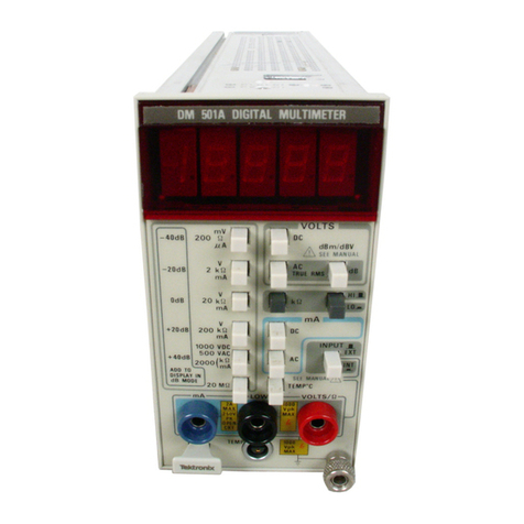
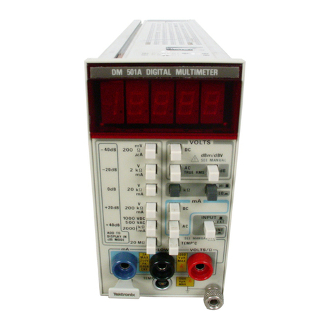
  9. Tektronix DM501A User manual

Tektronix DM501A User manual

Tektronix
COMMITTED
TO
EXCELLENCE
PLEASE
CHECK
FOR
CHANGE
INFORMATION
AT
THE
REAR
OF
THIS
MANUAL.
DM
501A
DIGITAL
MULTIMETER
Francais
Deutsch
AA
7
INSTRUCTION
MANUAL
Tektronix,
Inc.
P.O.
Box
500
7101
GE
Beaverton,
Oregon
97077
Serial
Number
LA
E.
070-2749-00
First
Printing
JUN
1979
Product
Group
75
Revised
APR
1986
Copyright
©1974,
1980
Tektronix,
Inc,
All
rights
reserved.
Contents
of
this
publication
may
not
be
reproduced
in
any
form
without
the
written
permission
of
Tektronix,
Inc.
Products
of
Tektronix,
Inc.
andits
subsidiaries
are
covered
by
U.S.
and
foreign
patents
and/or
pending
patents.
TEKTRONIX,
TEK,
SCOPE-MOBILE,
and
istered
trademarks
of
Tektronix,
inc.
i
are
reg-
Printed
in
U.S.A.
Specification
and
price
change
privileges
are
reserved.
Copyright
©
1974,
1980
TEKTRONIX
INC.
Tous
droits
réservés.
Le
contenu
de
ce
manuel
ne
peut
étre
reproduit
sous
quelque
for-
me
que
ce
soit
sans
l'accord
de
Tektronix
Inc.
Tous
les
produits
TEKTRONIX
sont
brevetés
US
et
Etranger
et
les
logotypes
TEKTRONIX,
TEK
SCOPE
MOBILE,
sont
déposés.
|
Imprimé
aux
USA.
TEKTRONI
X
se
réserve
le
droit
de
modifier
:
caractéristiques
et
prix
dans
le
cadre
de
développements
techno-
logiques,
Copyright
©
1974,
1980
durch
Tektronix,
Inc.
Alle
Rechte
vorbe-
halten.
Der
Inhalt
dieser
Publikation
darf
ohne
Genehmigung
von
Tektronix,
Inc.
nicht
weitergegeben
werden.
Produkte
von
Tektronix,
Inc.
und
seinen
Tochtergesellschaften
sind
durch
US-
und
Auslandspatente
und/oder
schwebende
Patente
abgedeckt.
TEKTRONIX,
TEK,
SCOPE-MOBILE
und
dif
sind
geschützte
Warenzeichen
von
Tektronix,
inc.
Gedruckt
in
U.S.A.
Spezifikations-
und
Preisánderungen
bleiben
vorbehalten.
©
1974,
1980
年
版権
所
有
テ
クト
ロニ
クス
社
。
不
許
複製
TEKTRONIX,
TEK.,
SCOPE-MOBILE,
は
テク
トロ
ニク
ス
社
の
登録
商
様
て
す
。
米国
に
て
印刷
、
仕
様
及び
価格
は
予告
な
く
〈
く
変更
する
場
合
が
あり
ます
.
INSTRUMENT
SERIAL
NUMBERS
Each
instrument
has
a
serial
number
on
a
panel
insert,
tag,
or
stamped
on
the
chassis.
The
first
number
or
letter
designates
the
country
of
manufacture.
The
last
five
digits
of
the
serial
number
are
assigned
sequentially
and
are
unique
to
each
instrument.
Those
manufactured
in
the
United
States
have
six
unique
digits.
The
country
of
manufacture
is
identified
as
follows:
8000000
100000
200000
300000
700000
Tektronix,
Inc.,
Beaverton,
Oregon,
USA
Tektronix
Guernsey,
Ltd.,
Channel
Islands
Tektronix
United
Kingdom,
Ltd.,
London
Sony/Tektronix,
Japan
Tektronix
Holland,
NV,
Heerenveen,
The
Netheriands
DM
5014
OPERATORS
SAFETY
SUMMARY
The
general
safety
information
in
this
part
ofthe
summary
is
for
both
operating
and
servicing
personnel,
Specific
warnings
and
cautions
will
be
found
throughout
the
manual
where
they
apply,
but
may
not
appear
in
this
summary.
TERMS
in
This
Manual
CAUTION
statements
identify
conditions
or
practices
that
could
result
in
damage
to
the
equipment
or
other
property.
WARNING
statements
identify
conditions
or
practices
that
could
result
in
personal
injury
or
loss
of
life.
As
Marked
on
Equipment
CAUTION
indicates
a
personal
injury
hazard
not
immediately
accessible
as
one
reads
the
marking,
or
a
hazard
to
property
including
the
equipment
itself.
DANGER
indicates
a
personal
injury
hazard
immediately
accessible
as
onereads
the
marking.
SYMBOLS
In
This
Manual
This
symbol
indicates
where
applicable
cautionary
or
other
information
is
to
be
found.
As
Marked
on
Equipment
#
DANGER
—
High
voltage.
&
Protective
ground
(earth)
terminal.
IN
ATTENTION
—
refer
to
manual.
Power
Source
This
product
is
intended
to
operate
from
a
power
source
that
will
not
apply
more
than
250
volts
rms
between
the
supply
conductors
or
between
either
supply
conductor
and
ground.
A
protective
ground
connection
by
way
of
the
grounding
conductor
in
the
power
cord
is
essential
for
safe
operation.
REV
A
AUG
1980
à
v
DM
SOTA
Grounding
the
Product
This
product
is
grounded
through
the
grounding
conductor
of
the
power
cord.
To
avoid
electrical
shock,
plug
the
power
cord
into
a
properly
wired
receptacle
before
connecting
tothe
product
input
or
output
terminals.
A
protective
ground
connection
by
way
of
the
grounding
conductor
in
the
power
cord
is
essential
for
safe
operation.
Danger
Arising
From
Loss
of
Ground
Upon
loss
of
the
protective-ground
connection,
ali
accessible
conductive
parts
(including
knobs
and
controis
that
may
appear
to
be
insulating)
can
render
an
electric
shock.
Use
the
Proper
Power
Cord
Use
only
the
power
cord
and
connector
specified
for
your
product.
Use
only
a
power
cord
that
is
in
good
condition.
Refer
cord
and
connector
changes
to
qualified
service
personnel.
Use
the
Proper
Fuse
To
avoid
fire
hazard,
use
only
the
fuse
specified
in
the
parts
list
for
your
product,
and
which
is
identical
in
type,
voltage
rating,
and
current
rating.
Refer
fuse
replacement
to
qualified
service
personnel.
Do
Not
Operate
in
Explosive
Atmospheres
To
avoid
explosion,
do
not
operate
this
product
in
an
atmosphere
of
explosive
gases
unless
it
has
been
specifically
certified
for
such
operation.
Do
Not
Operate
Without
Covers
To
avoid
personal
injury,
do
not
operatethis
product
without
covers
or
panels
installed.
Do
not
apply
power
to
the
plug-in
via
a
plug-in
extender.
yi
|
REV
A
AUG
1980
DM
501A
SERVICING
SAFETY
SUMMARY
FOR
QUALIFIED
SERVICE
PERSONNEL
ONLY
Refer
also
to
the
preceding
Operators
Safety
Summary.
Do
Not
Service
Alone
Do
not
perform
internal
service
or
adjustment
of
this
product
unless
another
person
capable
of
rendering
first
aid
and
resuscitation
is
present.
Use
Care
When
Servicing
With
Power
On
Dangerous
voltages
exist
at
several
points
in
this
product.
To
avoid
personal
injury,
do
not
touch
exposed
connections
and
components
while
power
is
on.
Disconnect
power
before
removing
protective
panels,
soldering,
or
replacing
components.
Power
Source
This
productis
intendedto
operate
from
a
power
source
that
will
not
apply
more
than
250
volts
rms
between
the
supply
conductors
or
between
either
supply
conductor
and
ground.
A
protective
ground
connectíon
by
way
of
the
grounding
conductor
in
the
power
cord
is
essential
for
safe
operation.
REV
A
AUG
1980
vii
DM
501A
RECAPITULATIF
DES
CONSIGNES
DE
SECURITE
Le
texte
ci-dessous,
divisé
en
deux
parties,
résume
les
consignes
de
sécurité
qui
doivent
étre
observées
à
toutes
les
phases
de
l'utilisation,
de
la
maintenance
et
des
réparations
de
l'appareil.
Consignes
de
sécurité
destinées
aux
utilisateurs.
Les
consignes
générales
de
sécurité
s'adressent
à
la
fois
aux
utilisateurs
et
au
personnel
de
maintenance.
Avertissements
et
précautions
à
respecter
sont
annotés
au
long
de
ce
manuel,
à
chaque
fois
que
l'utilisation
du
DM
501A
l'exige.
TERMES
Dans
ce
manuel
Les
nota
dénommés
«Attention»
indiquent
les
circonstances
ou
les
manipulations
pouvant
provoquer
des
détériorations
de
l'appareil
ou
de
tout
autre
équipement
associé.
Les
nota
dénommés
«Avertissement»
indiquent
les
circonstances
ou
les
manipulations
pouvant
entrainer
blessures
corporelles,
éventuellement
mortelles.
Gravés
sur
l'appareil
CAUTION
lattention).
Ce
mot
identifie
les
zones
de
risque
de
blessure,
non
immédiatement
perceptibles
ou
un
risque
éventuel
de
détérioration
de
l'appareil.
DANGER.
Ce
mot
indique
les
zones
de
risque
immédiat
pouvant
entrainer
blessures
ou
mort.
SYMBOLES
Dans
ce
manuel
IN
Ce
symbole
de
sécurité
signifie
:
se
reporter
au
manuel.
Gravés
sur
l'appareil
$
DANGER
—
Haute
tension
Protection
á
la
masse
A
ATTENTION
—
se
reporter
au
manuel
viii
REV
A
AUG
1980
DM
501A
Mise
à
la
masse
du
produit
La
mise
à
la
masse
du
DM
5014
s'effectue
à
l'aide
d'un
conducteur
de
masse
du
cordon
d'alimentation.
Pour
éviter
tout
choc
électrique,
insérer
la
prise
du
cordon
d'alimentation
dans
une
prise
de
distribution
correspon-
dante
avant
de
connecter
l'entrée
ou
les
terminaisons
de
sortie
de
l'appareil.
Pour
utiliser
l'appareil
en
toute
esie
pis
connexion
à
la
borne
de
masse
au
moyen
du
conducteur
de
masse
au
cordon
d'alimentation
est
indispensable.
Utiliser
le
cordon
d'alimentation
approprié
N'utiliser
que
lc
cordon
d'alimentation
et
la
prise
recommandés
pour
votre
appareil.
N'utiliser
qu'un
cor-
don
d'alimentation
en
bon
état.
Pour
effectuer
les
changements
de
cordons
d'alimentation
et
de
prises,
faire
appel
à
un
personnel
qualifié.
Utiliser
le
fusible
approprié
Pour
éviter
tout
risque
d'accident
(incendie...)
n'utiliser
que
le
fusible
recommandé
pour
votre
appareil.
Les
remplacements
de
fusible
doivent
toujours
étre
en
harmonie
avec
le
type,
la
vitesse
de
tension
et
la
vites-
se
de
courant.
Seul,
un
personnel
compétent
peut
procéder
à
un
changement
de
fusible.
Ne
pas
utiliser
l'appareil
en
atmosphére
explosives
Pour
éviter
toute
explosion,
ne
pas
utiliser
cet
appareil
dans
une
atmosphére
de
gaz
explosifs
à
moins
qu'une
telle
utilisation
n'ait
été
spécifiquement
reconnue
possible.
Ne
pas
Gter
les
capots
ou
panneaux
Pour
éviter
tout
incident
corporel
grave,
ne
pas
óter
les
panneaux
ou
capots
de
protection
de
l'appareil.
Celui-ci
ne
doit
pas
fonctionner
tant
que
les
panneaux
et
capots
n'ont
pas
correctement
été
mis
en
place.
Ne
pas
faire
fonctionner
l'appareil
sans
les
capots
et
panneaux
(pour
les
tiroirs
de
la
série
TM
500
uniquement)
Pour
éviter
tout
incident
corporel
grace,
ne
pas
utiliser
l'appareil
alors
que
les
capots
ou
panneaux
ne
sont
pas
remis
en
place.
N'appliquer
aucune
tension
au
tiroir
par
l'intermédiaire
d'un
cordon
d'extension.
CONSIGNES
DE
SECURITE
UNIQUEMENT
DESTINEES
AU
PERSONNEL
DE
MAINTENANCE
I!
est
indispensable
de
se
référer
également
aux
consignes
de
sécurité
à
l'attention
des
utilisateurs.
Ne
jamais
étre
seul
pour
procéder
à
l'entretien
de
l'appareil.
Agir
avec
précaution
si
l'on
effectue
une
réparation
alors
que
l'appareil
est
sous
tension
Des
tensions
dangereuses
existent
en
divers
points
de
l'appareil.
Pour
éviter
tout
risque
de
blessure
corpo-
relle,
ne
touchez
ni
aux
connexions
exposées
ni
aux
composants
alors
que
l'appareil
est
sous
tension.
Couper
l'alimentation
avant
d'enlever
les
panneaux
de
protection,
d'effectuer
des
soudures
ou
de
remplacer
des
composants.
Source
d'alimentation
Ce
produit
est
concu
pour
fonctionner
à
partir
d'une
source
d'alimentation
qui
n'appliquera
pas
plus
de
250
V
efficaces
entre
les
conducteurs
d'alimentation
ou
entre
chaque
conducteur
d'alimentation
et
la
terre.
Pour
utiliser
l'appareil
en
toute
sécurité,
une
connexion
à
la
masse
au
moyen
d'un
conducteur
de
masse
dans
le
cordon
d'alimentation
est
indispensable.
|
REV
A
AUG
1980
ix
DM
5014
SICHERHEITSANGABEN
Der
folgende
Text
enthált
in
zwei
Teilen
Angaben
über
Sicherheitsvorkehrungen,
die
jederzeit
bei
Betrieb,
Service
und
Reparatur
des
Gerátes
beachtet
werden
müssen.
SICHERHEITSANGABEN
FÜR
DEN
ANWENDER
Die
allgemeinen
Sicherheitsinformationen
in
diesem
Teil
der
Angaben
dienen
dem
Anwender-
und
Servicepersonal.
Spezielle
Warnungen
und
Hinweise
sind
überall
im
Handbuch
zu
finden,
müssen
jedoch
in
diesen
Angaben
nicht
erscheinen.
BEGRIFFE
in
diesem
Handbuch:
VORSICHTSHINWEISE
erláutern
Bedingungen,
die
zur
Zerstórung
des
Gerátes
oder
anderer
Gegen-
stánde
führen
kónnten.
WARNUNGSHINWEISE
erláutern
Bedingungen,
die
zu
Personenscháden
führen
kónnen
oder
lebens-
gefährlich
sind.
Markierungen
auf
dem
Gerát:
CAUTION
-
VORSICHT
weist
darauf
hin,
daB
durch
zufálliges
Berühren
an
einer
nicht
unmit-
telbar
zugánglichen
Stelle
Personenschaden
entstehen
kann,
oder
Schaden
am
Gerát
selbst.
DANGER
-
GEFAHR
weist
darauf
hin,
daß
durch
zufälliges
Berühren
an
einer
zugänglichen
Stelle
Personenschaden
éntstehen
kann.
SYMBOLE
In
diesem
Handbuch:
A
Dieses
Symbol
zeigt
an,
wo
Vorsicht
walten
zu
lassen
ist,
oder
wo
Informationen
zu
finden
sind.
Markierungen
auf
dem
Gerát:
4
GEFAHR
-
Hochspannung.
Schutzerdungskontakt
>
A
ACHTUNG
-
beziehen
Sie
sich
auf
das
Handbuch
Masseanschluß
des
Gerätes
Dieses
Gerät
wird
über
den
Schutzleiter
der
Versorgungseinheit
mit
Erdpotential
verbunden.
Zur
Vermeidung
von
elektrischen
Schlägen
ist
vor
der
Beschaltung
der
Ein-
und
Ausgänge
der
Netz-
stecker
in
eine
korrekt
verdrahtete
Steckdose
einzustecken.
Verwenden
Sie
den
Schutzleiter
nicht
als
einzige
Verbindung
zwischen
zwei
oder
mehreren
Geráten.
Zur
Vermeidung
von
elektrischen
Schlà-
gen
sind
die
Geráte
untereinander
mit
separaten
Leitungen
zu
verbinden.
x
REV
A
AUG
1980
DM
501A
Verwendung
eines
richtigen
Netzkabels
_
"
Verwenden
Sie
nur
Netzkabel,
die
für
die
Versorgungseinheit
geeignet
sind
und
die
sich
in
gutem
Zustand
befinden.
Für
detaillierte
informationen
über
Kabel
und
Stecker
beziehen
Sie
sich
auf
Abbildungen
innerhalb
des
Handbuches.
Ein
Austausch
von
Kabeln
und
Steckern
ist
nur
von
geschultem
Personal
vorzunehmen.
Verwendung
einer
richtigen
Sicherung
Zur
Vermeidung
von
Brandscháden
sind
nur
Sicherungen
zu
verwenden,
die
in
den
Teilelisten
dieses
Gerátes
aufgeführt
sind
und
die
in
Spannungs-
und
Stromwert
entsprechend
sind.
Ersatz
von
Sicherungen
ist
nur
von
geschultem
Personal
vorzunehmen.
Arbeiten
Sie
nicht
in
explosiver
Umgebung
Zur
Vermeidung
von
Explosionen
ist
die
Inbetriebnahme
dieses
Gerátes
in
explosiver
Umgebung
zu
unterlassen,
wenn
das
Gerát
nicht
dafür
geeignet
ist.
Entfernen
Sie
keine
Geháuseabdeckungen
Zur
Vermeidung
von
Personenscháden
sind
keine
Geháuseteile
zu
entfernen.
Auch
ist
das
Gerát
ohne
Geháuse
nicht
in
Betrieb
zu
nehmen.
Arbeiten
Sie
nicht
ohne
Geháuseabdeckung
Zur
Vermeidung
von
Personenscháden
ist
das
Gerát
nicht
ohne
Geháuse
in
Betrieb
zu
nehmen.
Der
Einschub
solite
nicht
über
einen
Verlángerungsadapter
betrieben
werden.
SICHERHEITSANGABEN
FÜR
DEN
SERVICE
NUR
FÜR
GESCHULTES
PERSONAL
Beziehen
Sie
sich
auch
auf
die
vorangehenden
Sicherheitsangaben
für
den
Anwender.
Führen
Sie
keine
Servicetátigkeiten
alleine
durch
Nehmen
Sie
an
dem
Gerät
keine
Service-
oder
Einstellarbeiten
vor,
wenn
nicht
eine
andere
Person
ver-
fügbar
ist,
um
im
Bedartstall
Erste
Hilfe
oder
Wiederbelebungsversuche
zu
leisten.
Lassen
Sie
besondere
Vorsicht
walten,
wenn
Sie
an
einem
unter
Spannung
stehenden
Gerát
arbeiten
An
verschiedenen
Stellen
im
Gerät
liegen
hohe
und
damit
gefährliche
Spannungen.
Zur
Vermeidung
von
Personenschaden
sind
soiche
Stellen
und
Bauteile
nicht
zu
berühren,
während
Betriebsspannung
anliegt.
Vor
dem
Entfernen
von
Gehäuseteilen,
Löten
oder
Ersetzen
von
Bauteilen
ist
immer
die
Betriebsspan-
nung
zu
entfernen.
Netzspannungsversorgung
Die
Betriebsspannung
für
dieses
Gerät
darf
250
Van
nicht
überschreiten
und
ist
an
die
Versorgungsiei-
tungen
bzw.
an
eine
Versorgungsleitung
und
Masse
anzulegen.
Innerhalb
des
NetzanschluBkabels
muß
ein
Schutzleiter
vorhanden
sein,
der
mit
Gerátemasse
verbunden
ist.
REV
A
AUG
1980
xi
DM
5014
ご
使用
の
前
に
DM
501A
型
を
安全
に
お
合い
いた
だ
だく
だめ
に
、
Pe
HR,
修理
上
の
注意
事項
が
、
大
きく
2
環
目
に
分
れ
て
述べ
られ
て
い
ます
。
操作
上
の
注意
操作
上
の
注意
は
、
オ
ペレ
ー
タ
の
方
に
も
サー
ビス
・
エ
ンジ
ニア
の
方
に
も
共通
し
て
いま
す
。
こ
の
マニ
ュ
ア
テル
の
人
各所
に
特
中
の
注意
壮
き
が
あり
ます
が
、
こ
れ
に
よく
従っ
て
下さ
い
。
7
mi
vafra
Xu
(WARNING)
の
項
は
人
体
に
摂
傷
を
及ぼ
し
た
り
危
葵
を
与え
る
麗
れ
の
ある
場合
の
注意
で
す
。
注意
(CAUTION)
の
項
は
本
機器
また
は
他
の
接続
機器
に
Hif
Mix
riiv
b
5IbOOiG
CS.
機器
上
の
用
庄
CAUTION
X
JUS
AL
TAS
SBOE
A
USO
AS
B
ET
EAEYISndb9EzdoccikXArsve.
DANGER
と
起き
され
で
いる
部
分
は
、
人
人
体
に
危険
を
友
ぼ
し
ます
の
で
まま
を
触れ
な
いで
まさ
い
。
Til
os
マニ
ュ
ア
ル
中
の
記号
/\
ERRE
TOR.
機器
上
の
記号
e»
MH
ach
IN
ATTENTION-—-e
=
a
Tr
aM
xii
TRE.
WOO
DM
501A
X
(BA
Van
DIREI
Ro
TAREA
ます
。
WMS
a
ZERIT
SCA,
A7
7
TEN
(LEER
2
DE.
人
人
出力
コネ
クタ
を
接続
する
曽
に
行っ
て
ト
Sv.
2
古
ま
な
は
それ
以上
の
機器
の
間
だ
け
で
接地
線
を
接続
する
だ
け
で
な
く
、
電
気
釣
シ
ョ
ッ
ク
を
避け
る
た
め
接
地
瑞
了
す
に
接地
し
て
下さ
い
。
@
AUG
1980
電源
コード
dl
る
電源
コー
ド
及
び
コ
ネ
ク
タ
を
使用
し
て
下さ
。
電源
コー
ド
は
据
傷
の
な
いも
の
を
お
使い
下さ
きい
。
電源
コー
ド
と
コネ
クタ
に
関す
る
詳細
は
、TM5OO
志
源
本
体
の
アニュアル
を
ご
参議
下さい
。
コー
ド
と
コネ
クタ
の
変換
の
際
は
当社
エン
ジニ
ア
に
お
た
ず
ね
ドド
きい
。
ヒュ
ー
ズ
|
en.
リス
ト
に
記載
きれ
て
で
てい
cee
E
E
Jo
t
à
—
ZX
2%
ORE
Yo
M
ヒュ
ー
ズ
交換
の
際
は
、
当
社
エ
ンジ
ニア
に
お
たずね
下さ
い
。
爆発
防止
危険
防
目
の
た
め
、
提
発
性
の
ダス
が
膨
因
に
ある
よう
な
所
で
は
作動
きせ
な
いで
下さ
い
。
カバ
ー、
フ
バネ
キル
人
体
へ
の
指
偽
を
避け
る
ため
、
機器
の
カバ
ー
や
パネ
ル
は
也
り
は
ず
き
さ
な
いで
下さ
きい
。
カ
バー
や
バネ
ル
を
は
ず
し
だ
まま
、
機器
を
作動
きせ
な
いで
下
き
い
。
カバ
ー
の
扱い
に
つい
て
人 体
へ
の
損傷
を 遅
け
る
た
め
、
機
器
の
カバ
ー
や
パネ
ル
を
取
り
は
ず
し
た
まま
作動
き
せな
いで
まさ
い
。
ま
た
ブラ
グイ
ン
・
LIRFTILEATIH
ERLITT
PEL
@
AUG
1980
DM
501A
サー
ビス
上
の
注意
サー
ビス
・
エ
ンジ
ニア
の
方
へ
“PAE
LOIRET
RBA
KE.
1
人
で
サー
ビス
を
行わ
な
いで
下さ
きい
。
a
は
修理
は
、
Jj
c
Nur
TEN
Li
で
きる
人
が
いる
He
Tir
T
Fais
電源
を
入れ
た
た
場合
の
注意
機器
内
iin
ELO
S6
HY
£d.
Aft
Bat
+
8
ren,
MD
A
o
TIO
DAME,
HNL
Ti da
bus
LT
AO
PKR
バネ
ル
の
取り
は
ず
し
、
ハ
ン
x6.
A
co
sc
TR
を
行う
Hiji
は
、
電
源
を
必ず
切っ
て
トト
きい
。
電源
DM
501A
型
は
生
泊
フー
ド
の
線
間
ある
lia
kos
57»
KIN
A250
Vrms
Li
osi
oou
CT
Lx
Te
‘be
全
の
た
め
に
湯泊
ロー
ド
の
アー
ス
線
で
きち
ん
と
寺地
し
~
tos
xiii
DM
5014
Perro
DM
501A
Digital
Multimeter.
xiv
|
@
AUG
1980
Section
1—DM
501A
SPECIFICATION
introduction
The
DM
501A
Digital
Multimeter
measures
dc
voltage
and
current,
ac
voltage
and
current,
dBm,
dBV,
resistance,
and
temperature.
The
ac
functions
are
ac
coupled
only,
true
rms
responding.
All
the
functions
and
ranges
are
front
panel
push
button
selected,
including
the
rear
interface
connector
input.
Readout
in
dBm
or
dBV
is
selected
by
an
internal
jumper.
The
unit
is
shipped
with
the
internal
jumper
in
the
dBm
position.
The
readout
is
a
0.4"
high,
4
1/2
digit
display
using
seven
segment
LED.
The
decimai
point
is
automatically
positioned
depending
on
the
selected
operating
range
of
the
instrument.
Polarity
indication
is
automatic.
Accessories
Standard
accessories
include
this
instruction
manual,
a
set
of
test
leads
and
the
TEKTRONIX
P6601
temperature
probe
with
its
instruction
manual.
The
P6601
temperature
probe
and
temperature
measurement
capabilities
are
deleted
for
Option
2
in-
struments.
Performance
Conditions
The
electrical
characteristics
are
valid
only
if
the
DM
501A
has
been
calibrated
at
an
ambient
temperature
between
+21°C
and
+25°C
andis
operating
at
an
ambient
temperature
between
0°C
and
+50°C,
uniess
otherwise
noted.
Items
listed
in
the
Performance
Requirements
column
of
the
Electrical
Characteristics
are
verified
by
completing
the
Performance
Check
in
the
Calibration
section
of
this
manual.
These
items
are
either
explanatory
notes
or
performance
characteristics
for
which
no
limits
are
specified.
Table
1-1
ELECTRICAL
CHARACTERISTICS
(Front
Panel)
Characteristics
Performance
Requirements
Supplemental
information
DC
VOLTMETER
Accuracy
for
200
mV,
2
V,
20
V
200
V
and
1000
V
ranges
+18°C
to
+28°C
200
mV
range
|
scale)
2
V
to
200
V
ranges
scale)
1000
V
range
scale)
0°C
to
+18°C,
+28°C
to
450?
C
200
mV
to
200
V
range
|
+(0.1%
of
reading
+
0.025%
of
full
|
scale)
+(0.05%
of
reading
+
0.015%
of
full
X
(0.0596
of
reading
+
0.01%
of
full
(0.05%
of
reading
+
0.02%
of
full
1000
V
range
|
+(0.1%
of
reading
+
0.05%
of
full
|
|
scale)
|
@
1-1
Specification—DM
501A
Characteristics
Common
Mode
Rejection
Ratio
Normal
Mode
Rejection
Ratio
Maximum
Resolution
Step
Response
Time
Input
Resistance
Maximum
input
Voltage
VOLTS/A
to
LOW
VOLTS/O
to
ground
LOW
to
ground
input
Connectors
Table
1-1
(cont)
Performance
Requirements
DC
VOLTMETER
(cont)
100
dB
at
dc.
80
dB
at
50
and
60
Hz.
'
60
dB
at
50
or
60
Hz
+0.2
Fiz.
|
AC
VOLTMETER
(TRUE
RMS)
Accuracy
for
200
mV,
2V,
20V
200
V
and
500
V
ranges
+18°C
to
+28°C
|
200
mV
to
200
V
ranges
40
Hz
to
10
KHz
20
Hz
to
40
Hz
and
10
kHz
to
20
kHz
500
V
range
40
Hz
to
10
kHz
20
Hz
to
40
Hz
and
10
kHz
to
20
kHz
0°C
to
18?
C,
+28°C
to
+50°C
200
mV
to
200
V
ranges
40
Hz
to
10
kHz
20
Hz
to
40
Hz
and
10
kHz
to
20
kHz
500
V
range
40
Hz
to
10
kHz
20
Hz
to
40
Hz
and
10
kHz
to
20
kHz
1-2
+(0.6%
of
reading
+
0.05%
of
full
scale)
+{1.0%
of
reading
+
0.05%
of
full
scale)
|
+(0.6%
of
reading
+
0.2%
of
full
scale)
+(1.0%
of
reading
+
0.2%
of
full
scale}
+(0,8%
of
reading
+
0.075%
of
full
scale)
+(1.3%
of
reading
+
0.075%
of
full
scale)
+(0.8%
of
reading
+
0.3%
of
full
scale)
+(1.3%
of
reading
+
0.3%
of
full
scale)
Supplemental
information
With
a
1
kO
unbalance.
10
pV.
<1
second.
10
MQ
20.5%.
1000
V
peak.
1000
V
peak.
1000
V
peak.
Front
panel
(EXT)
or
rear
interface
(INT)
Input
signal
must
be
between
5%
and
100%
of
fuli
scale.
The
500
V
range
requires
a
dynamic
input
signal
between
500
V
and
100
V
rms.
Table
1-1
(cont)
Characteristics
Performance
Requirements
AC
VOLTMETER
(TRUE
RMS)
(cont)
Common
Mode
Rejection
Ratio
>
60
dB
at
50
and
60
Hz.
Maximum
Resolution
Response
Time
input
Impedance
Input
Connectors
Maximum
Input
Voltage
VOLTS/Q
to
LOW
VOLTS/Q
to
ground
LOW
to
ground
Crest
Factor
H
1
DECIBELS
(dB)—
TRUE
RMS
Accuracy
for
—40
dB,
~20
dB,
0
dB,
+20
dB
and
+40
dB
ranges
+18°C
to
+28
C
+20
dB
to
-15
dB
+0.5
dB
20
Hz
to
20
kHz
—15
dB
to
一
20
dB
10.5
dB
20
Hz
to
2
kHz
+1.5
dB
2
kHz
to
10
kHz
0*C
to
18?
C,
+28°C
to
+50°C
+20
dB
to
—15
dB
+1.1
dB
20
Hz
to
20
kHz
—15
dB
to
-20
dB
+1,1
dB
20
Hz
to
2
kHz
+2.1
dB
2
kHz
to
10
kHz
Maximum
Resolution
Response
Time
Input
Impedance
Maximum
input
Voltage
VOLTS/Q
to
LOW
VOLTS/A
to
ground
LOW
to
ground
"Equivalent
to
54
dBV
or
56.2
dBm.
REV
B
MAY
1980
Specification—DM
501A
Supplemental
Information
With
a
1kQ
unbalance.
10
wv.
«2
seconds.
10
MQ
10.5%
paralleled
by
160
pF.
Front
panel
(EXT)
or
rear
interface
(INT).
500
V
rms
or
500
Vdc
not
to
exceed
1000
V
peak.
1000
V
peak.
1000
V
peak.
4
at
fulí
scale.
Typicalty
<
+2.5
dB
10
kHz
to
20
kHz.
Typically
<
£3.1
dB
10
kHz
to
20
kHz.
0.1
dB.
«2
seconds.
10
MO
paralleled
by
160
pF.
500
v
rms
or
600
Vdc
not
to
exceed
1000
V
peak."
1000
V
peak.
1000
V
peak.
1-3
Specification—
DM
501A
Table
1-1
(cont)
Characteristics
Performance
Requirements
Suppiemental
information
Crest
Factor
|
4
at
fuli
scale.
Ref
Voitage
|
|
dBV
|
|
t
V:
dBm
0.7746-V
{1
mW
dissipated
into
|
600
9).
Selected
by
internal
jumper.
|
Front
panel
(EXT)
or
rear
interface
input
Connectors
OHMMETER
Accuracy
for
200
Q,
2
kQ,
20
kQ,
pot
TRUE
200
kQ,
2000
kQ
and
20
MQ
ranges.
+18°C
to
+28°C
i
200
Q
to
200
kN
LOQ
+{0.15%
of
reading
+
0.015%
of
full
2
k(
to
2000
kQ
HIN
|
Scale)
2000
kN
LO
|
+{0.3%
of
reading
+
0.015%
of
full
scale)
20
MQ
HN
+(0.5%
of
reading
+
0.015%
of
full
scale)
0°C
to
+18°C,
+28°C
to
+50°C
200
Q
to
200
kQ
LO
Q
+(0.3%
of
reading
+
0.025%
of
full
2
kM
to
2000
kM
HIN
scale)
2000
kQ
LO
Q
1(1.2%
of
reading
+
0.025%
of
fuil
20
MQ
HI
Q
scale)
Maximum
input
Volts
Any
Range
250
V
peak.
Measuring
Current
and
Full
Source
V
Max
at
Scate
Volts
Range
Current
Full
Scale
]
a
il
HI
OQ
200
Q
1.0
mA
0.2
V
2
KQ
1.0
mA
2.0
V
20
kO
0.1
mA
20V
200
kQ
10.0
uA
20V
2000
kN
1.0
uA
20V
20
MQ
0.1
uA
20V
LO
?
200
Q
1.0
2
kQ
0.1
20
kQ
10.0
200
kQ
1.0
2000
KG
0.1
20
MO
0.1
1-4
REV
A
AUG
1979
Characteristics
Maximum
Resolution
Response
Time
Maximum
Open
Circuit
Voltage
input
Connectors
Accuracy
for
200
uA,
2
mA,
20
mA,
200
mA
and
2000
mA
ranges.
+18°C
to
+28°C
0°C
to
+18°C,
+28°C
to
+50°C
Response
Time
input
Resistance
Maximum
Input
Current
Table
1-1
(cont)
Performance
Requirements
I
DC
AMMETER
+(0.2%
of
reading
+
0.015%
of
full
scale)
+{0.3%
of
reading
+
0.025%
of
full
scale)
Specitication—DM
501A
Supplemental
information
10
mA.
"<2
seconds,
200
Q
to
2000
kn.
<10
seconds,
20
MQ
scale.
«6
V.
Front
panel
(EXT)
or
rear
interface
(INT).
<1
second.
Approximate
Range
Resistance
200
uA
10
KQ
100.0
Q
102
N
12
NQ
04
Q
2
A
any
range.
Maximum
Open
Circuit
Input
A
250
V
peak.
Voltage
(mA
to
LOW)
Maximum
Floating
Voltage
mA
to
ground
ON
1000
V
peak.
LOW
to
ground
ooo...
|
1000
V
peak.
Input
Connectors
A
A
See
ea)
Eront
panel
only.
Maximum
Resolution
|
OA,
Accuracy
for
200
uA,
2
mA,
20
mA,
200
mA
and
2000
mA
ranges.
20
Hz
to
10
kHz
(Sinewave)
+18°C
to
+28°C
AC
AMMETER
+(0.6%
of
reading
+
0.05%
of
full
scale)
0*C
to
+18°C,
+28°C
to
+50°Q
(0.7%
of
reading
+
0.075%
of
full
Response
Time
input
Resistance
.
scale)
Input
current
must
be
between
5%
and
100%
of
full
scale.
Usable
to
20
kHz.
<2
seconds.
Approximate
Range
Resistance
200
uA
1.0
KQ
1000
Q
102
Q
200
mA
12
Q
2000
mA
04
Q
REV
A
AUG
1979
1-5
Specification—-DM
501A
Characteristics
Maximum
Input
Current
Maximum
Open
Circuit
Input
Voltage
(mA
to
LOW)
Maximum
Floating
Voltage
mA
to
ground
LOW
to
ground
Imput
Connectors
Maximum
Resolution
Accuracy
for
the
-62*C
to
+240°C
range.
+18°C
to
+28°C
ambient
Probe
calibrated
to
instrument
Any
probe
0°C
to
+18°C,
+28°C
to
+50°C
input
Connectors
1-6
Table
1-1
(cont)
Performance
Requirements
Supplemental
information
AC
AMMETER
(cont)
TEMPERATURE
+2°C
from
—62°C
to
+150*C.
+4°C
from
-62°C
to
+150°C.
+2°C
to
-8*C
from
+150°C
to
+240°C.
Add
1.5°C
to
the
above
tolerance
in
each
direction.
+9°Cto-8°C
from
+150°C
to
+240°C
2
A
any
range.
250
V
peak.
i
1000
V
peak.
i
1000
V
peak
Front
panel
oniy.
10
nA
REV
A
AUG
1980
Specification--DM
501A
Table
1-1
(cont)
ELECTRICAL
CHARACTERISTICS
(Rear
Interface
Inputs)
Characteristics
:
Performance
Requirements
Supplemental
Information
Maximum
input
Voltage
(dc,
ac,
d8,
and
ohms)
Pin
28B
to
28A
200
V
peak.
Equivaient
to
43
dBV
or
45.2
dBm.
Pin
28B
to
ground
200
V
peak.
Pin
28A
to
ground
200
V
peak.
DC
VOLTMETER
(REAR
INTERFACE
INPUTS)
Accuracy
for
200
mV,
2
V,
20
V,
|
200
V
and
1000
V
ranges.
+18°C
to
+28°C
200
mV
range
+(0.05%
of
reading
+
0.015%
of
full
scale)
2
V
to
200
V
range
x:
(0.0596
of
reading
+
0.01%
of
full
scale)
|
1000
V
range
+{0.05%
of
reading
+
0.02%
of
fuil
scale}
0°C
to
+18°C,
+28°C
to
+50°C
200
mV
to
200
V
range
+{0.1%
of
reading
+
0.025%
of
full
scale)
1000
V
range
+(0.1%
of
reading
+
0.05%
of
fuil
scale)
(continues
on
next
page)
REV
B
AUG
1980
i
1-7
Specitication—DM
501A
Table
1-1
(cont)
Characteristics
Performance
Requirements
Suppiemental
Information
AC
VOLTMETER
(REAR
INTERFACE
INPUTS)
Accuracy
for
200
mV,
2
V,
20
V,
200
V
and
500
V
ranges.
+18°C
to
+28°C
200
mV
to
200
V
range
40
Hz
to
10
kHz
input
signal
must
be
between
5%
and
100%
of
full
scale
input.
The
500
V
range
is
limited
to
between
200
V
peak
and
100
V
rms.
£(1.6%
of
reading
+
0.05%
of
full
scale)
20
Hz
to
40
Hz
and
10
kHz
to
20
kHz
+{2.0%
of
reading
+
0.05%
of
full
scale)
500
V
range
40
Hz
to
10
kHz
+(1.6%
of
reading
+
0.2%
of
full
|
|
scale)
.
20
Hz
to
40
Hz
and
+(2.0%
of
reading
+
0.2%
of
full
10
kHz
to
20
kHz
;
scale)
0°C
to
+18°C,
+28°C
to
+50°C
200
mV
to
200
V
range
40
Hz
to
10
kHz
1(1.8%
of
reading
+
0.075%
of
fuli
scale)
20
Hz
to
40
Hz
and
1(2.3%
of
reading
+
0.075%
of
full
10
kHz
to
20
khz
scale)
500
V
range
40
Hz
to
10
kHz
+{1.8%
of
reading
+
0.3%
of
full
scale)
20
Hz
to
40
Hz
and
+{2.3%
of
reading
+
0.3%
of
full
10
kHz
to
20
kHz
scale)
DECIBELS
(dB)—
TRUE
RMS
(REAR
INTERFACE
INPUTS)
Accuracy
for
—40
dB,
—20
dB,
0
dB,
+20
dB
and
+40
dB
ranges
+18°C
to
+28°C
+20
dB
to
—15
dB
30.6
dB
20
Hz
to
20
kHz
—15
dB
to
—20
dB
|
£06
dB
20
Hz
to
2
kHz
Typically
+1.6
dB
2
kHz
to
10
kHz
«2.6
dB
10
kHz
to
20
kHz
0°C
to
+18°C,
+28°C
to
+50°C
+20
dB
to
—15
dB
+1.2
dB
20
Hz
to
20
kHz
ー15
dB
to
一
20
dB
+1.2
dB
20
Hz
to
2
kHz
Typically
—
+2.2
dB
2
kHz
to
10
kHz
«3.2
dB
10
kHz
to
20
kHz
1-8
REV
B
JAN
1980

Other manuals for DM501A

3

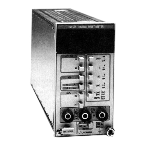
Other Tektronix Multimeter manuals

Tektronix DM501A User manual

Tektronix

Tektronix DM501A User manual

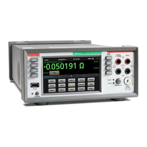
Tektronix KEITHLEY DMM6500 Use and care manual

Tektronix

Tektronix KEITHLEY DMM6500 Use and care manual

Tektronix DM2510 Manual

Tektronix

Tektronix DM2510 Manual

Tektronix DMM912 User manual

Tektronix

Tektronix DMM912 User manual

Tektronix Keithley DMM7510 User manual

Tektronix

Tektronix Keithley DMM7510 User manual

Tektronix DMM150 User manual

Tektronix

Tektronix DMM150 User manual

Tektronix 7D13 User manual

Tektronix

Tektronix 7D13 User manual

Tektronix 47E5A User manual

Tektronix

Tektronix 47E5A User manual

Tektronix DMM4040 User manual

Tektronix

Tektronix DMM4040 User manual

Tektronix KEITHLEY 2100 Use and care manual

Tektronix

Tektronix KEITHLEY 2100 Use and care manual

Tektronix THM500 Series User manual

Tektronix

Tektronix THM500 Series User manual

Tektronix TX-DMM TX1 User manual

Tektronix

Tektronix TX-DMM TX1 User manual

Tektronix DM 504A User manual

Tektronix

Tektronix DM 504A User manual

Tektronix DM 502 User manual

Tektronix

Tektronix DM 502 User manual
Tektronix Keithley 3700A Series User manual

Tektronix

Tektronix Keithley 3700A Series User manual

Tektronix VX4234 User manual

Tektronix

Tektronix VX4234 User manual

Tektronix DM 502 User manual

Tektronix

Tektronix DM 502 User manual

Tektronix DMM4040 Setup guide

Tektronix

Tektronix DMM4040 Setup guide

Tektronix DM 504A User manual

Tektronix

Tektronix DM 504A User manual

Tektronix KEITHLEY DAQ6510 Use and care manual

Tektronix

Tektronix KEITHLEY DAQ6510 Use and care manual

Tektronix DM 5010 User manual

Tektronix

Tektronix DM 5010 User manual

Tektronix DM 502A User manual

Tektronix

Tektronix DM 502A User manual

Tektronix 7D13 User manual

Tektronix

Tektronix 7D13 User manual
Tektronix Keithley DMM7512 Instructions for use

Tektronix

Tektronix Keithley DMM7512 Instructions for use

Popular Multimeter manuals by other brands

Megger AVO300 Series user manual

Megger

Megger AVO300 Series user manual

Agilent Technologies U1272A quick start guide

Agilent Technologies

Agilent Technologies U1272A quick start guide

Keithley 195A Quick reference guide

Keithley

Keithley 195A Quick reference guide

Sealey TM104 instructions

Sealey

Sealey TM104 instructions

PCE Instruments LCT 1 user manual

PCE Instruments

PCE Instruments LCT 1 user manual

Gigahertz Solutions DMM3-Set manual

Gigahertz Solutions

Gigahertz Solutions DMM3-Set manual

SW-Stahl 32230L instruction manual

SW-Stahl

SW-Stahl 32230L instruction manual

Extech Instruments EN300 user guide

Extech Instruments

Extech Instruments EN300 user guide

PeakTech 1020 Operation manual

PeakTech

PeakTech 1020 Operation manual

IDEAL 61-797 manual

IDEAL

IDEAL 61-797 manual

HT HT65 user manual

HT

HT HT65 user manual

Brymen BM252 user manual

Brymen

Brymen BM252 user manual

FLIR EXTECH INSTRUMENTS EX520 user guide

FLIR

FLIR EXTECH INSTRUMENTS EX520 user guide

LOVATO ELECTRIC DMG210L01 instruction manual

LOVATO ELECTRIC

LOVATO ELECTRIC DMG210L01 instruction manual

Fluke 1587 Specifications

Fluke

Fluke 1587 Specifications

Kaiweets HT118A manual

Kaiweets

Kaiweets HT118A manual

Chauvin Arnoux C.A 6550 user manual

Chauvin Arnoux

Chauvin Arnoux C.A 6550 user manual

Almemo 2190-2 operating instructions

Almemo

Almemo 2190-2 operating instructions

manuals.online logo
manuals.online logoBrands
  • About & Mission
  • Contact us
  • Privacy Policy
  • Terms and Conditions

Copyright 2025 Manuals.Online. All Rights Reserved.