EFA VBE-M User manual

MOBILE ANIMAL
STUNNING DEVICE
VBE-M
MAULBRONN, 1
ST
EDITION, MAY 2021
Index number:
________ M0056/M
Software version:
____________ E5.5
Serial number:
_____/____/_____

Mobile animal stunning device VBE-M
2
CAUTION!
This user manual is an integral part of the VBE-M animal stunning
device. It is absolutely necessary to read it carefully before installing,
commissioning and using the device.
Please contact us in case of any questions or concerns.
The stunning system comes equipped with:
1. VBE-M animal stunning device (called the VBE-M device )
●VBE-M stunning unit (called the VBE-M )
● power system
● trolley with tongs cover (called the trolley )
2. stunning tongs (called the tongs )
3. USB converter with cable (called the USB converter )
This user manual applies to the animal stunning device VBE-M .
CAUTION!
The device meets the requirements of:
● Council Regulation (EC) No 1099/2009 of 24 September 2009 on the protection of
animals at the time of killing ( Regulation 1099/2009 );
● FSIS Directive 6900.2 of 15 August 2011 - “Humane Handling and Slaughter of
Livestock” ( FSIS Directive ).
The SD card contains the user manual of the device.
TABLE OF
CONTENTS
WORK SAFETY AND OPERATING RULES 4
OPIS I OCENA RYZYKA RESZTKOWEGO 4
2.1. Description of residual risk 4
2.2. Assessment of residual risk 5
CONTENTS OF THE SDHC CARD 5
INFORMATION AND WARNING SIGNS 5
4.1 Markings on the housing 5
4.2 Warning and information pictograms 6
4.3 Signal lights 6
DESIGN, TECHNICAL DATA AND PARTS LIST 6
5.1 Types of tongs 7
INTENDED USE AND PRINCIPLE OF OPERATION 7
MAIN CONTROLLER 8
7.1 Control panel - buttons, indicators and displays 8

Mobile animal stunning device VBE-M
3
7.2 Main controller parameters that can be reprogrammed 9
7.3 Description of parameters tP1, tP2 and tP3 - stunning modes 11
INSTALLING AND TURNING THE DEVICE ON 12
8.1 Turning the device on 12
8.2 Starting the device 14
8.3 The course of the stunning process 14
MAIN CONTROLLER OPERATION 17
9.1 Unlocking parameters 17
9.2 Editing parameters 17
9.3 Setting the date and time 17
STUNNING PARAMETER RECORDER 18
10.1 Parameter recording 18
10.2 Parameter reading 18
DOWNLOADING AND UPLOADING STUNNING PARAMETERS 19
11.1 Uploading parameters to the device from the SDHC card 19
11.2 Downloading parameters from the device to the SDHC card 19
CONNECTING THE VBE-M DEVICE TO A PC 20
12.1 Installation of the USB converter drivers 20
12.2 Installation of the EFA software for VBE-M - PC communication 22
12.3 Launching the program for VBE-M - PC communication 23
12.4 Program configuration for VBE-M - PC communication 24
12.5 Working with the VBE-M - PC communication program 27
CLEANING, MAINTENANCE, REPAIRS AND DISPOSAL 28
13.1 Cleaning 28
13.2 Maintenance 28
13.3 Repairs 29
13.4 Disposal 29
TROUBLESHOOTING 29

Mobile animal stunning device VBE-M
4
1. WORK SAFETY AND OPERATING RULES
The device operates in two modes:
1. battery mode - when it is not connected to the mains;
2. mains mode - when it is connected to the mains.
CAUTION!
Read the entire user manual carefully before using the device.
Failure to comply with the safety rules listed below threatens work safety.
● persons who operate and maintain the device must read this manual or undergo training in operating the
device as well as health and safety rules at the given workplace;
● the device cannot be used for purposes other than intended;
● all repairs should be carried out by the authorized service centre. Unauthorized modifications or repairs
will void the warranty. The manufacturer is not responsible for damages resulting from malfunction of the
device in which unauthorized changes have been made;
● maintenance work should be carried out after disconnecting the device from the power supply;
● it is forbidden to use the device with visible defects;
● in mains mode the device must be connected to the grounded mains;
● it is forbidden for minors or untrained persons to operate the device.
The device is equipped with an electronic protection system against electric shock.
However, it is forbidden to touch the electrodes.
CAUTION!
Wires and sockets of the device must not be exposed to water.
The inspection window of the device should always be tightly closed.
After finishing work, it is absolutely necessary to:
● disconnect the device from the mains (switch off the power system / disconnect from the mains);
● properly secure all elements of the stunning system;
● put all covers on the device sockets to protect against moisture;
Failure to follow the above recommendations may damage the device.
2. OPIS I OCENA RYZYKA RESZTKOWEGO
2.1. Description of residual risk
Although the manufacturer takes responsibility for the construction and proper marking of the device, in order
to eliminate hazards during operation and maintenance, certain risk elements cannot be avoided. Residual
risk results from incorrect or improper handling of the device by the operator. The greatest danger occurs
when performing the following prohibited actions:
● operating the device without reading the user manual or without training in operating the device as well
as health and safety rules at the given workplace;
● using the device for purposes other than intended;
● unauthorized modifications or repairs to the device;
● carrying out maintenance work without disconnecting the device from the power supply;
● using the device with visible defects;
● connecting the device to the ungrounded mains while working in mains mode ;
● operating the device by minors or untrained persons.
Mobile animal stunning device VBE-M
5
2.2. Assessment of residual risk
Recommendations to minimize residual risk (for people and the environment) when operating the device:
● carefully reading the user manual and undergoing training in operating the device as well as health and
safety rules at the given workplace ;
● using the device only for its intended purpose;
● carrying out modifications and repairs only by the authorized service centre;
● carrying out maintenance work only after disconnecting the device from the power supply;
● checking the technical condition of the device always before operation;
● connecting the device to the grounded mains while working in mains mode ;
● preventing minors or untrained persons from accessing the device.
CAUTION!
Residual risk occurs in case of failure to comply with recommendations and guidelines listed
above.
3. CONTENTS OF THE SDHC CARD
On the SDHC card of the device there are folders Deutsch , English , Español and Français ,
containing materials and information intended for device users:
Table 1 Contents of subfolders
No.
Subfolder name
Content
1
User manual
User manual, specification, parts list.
2
Parameters
The pigpar3.bin file with service parameters.
3
ADAUSBDrv
USB converter installation files
4
PC
Software installation files for connecting the VBE-M to a PC
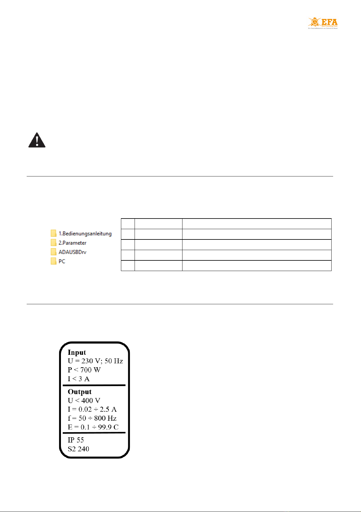
4. INFORMATION AND WARNING SIGNS
4.1 Markings on the housing
Fig. 1 Information frame
Input
U = 230 V (rated voltage)
f = 50 Hz (frequency)
P < 700 W (maximum power)
I < 3 A (maximum current)
Output
U < 400 V (maximum output voltage)
I < 0.02 ÷ 2.5 A (stunning current)
f = 50 ÷ 800 Hz (frequency)
E = 0.1 ÷ 99.9 C (electric charge)
IP55
S2 240 (duty cycle)
Mobile animal stunning device VBE-M
6
4.2 Warning and information pictograms
Table 2 The meaning of pictograms placed on the device
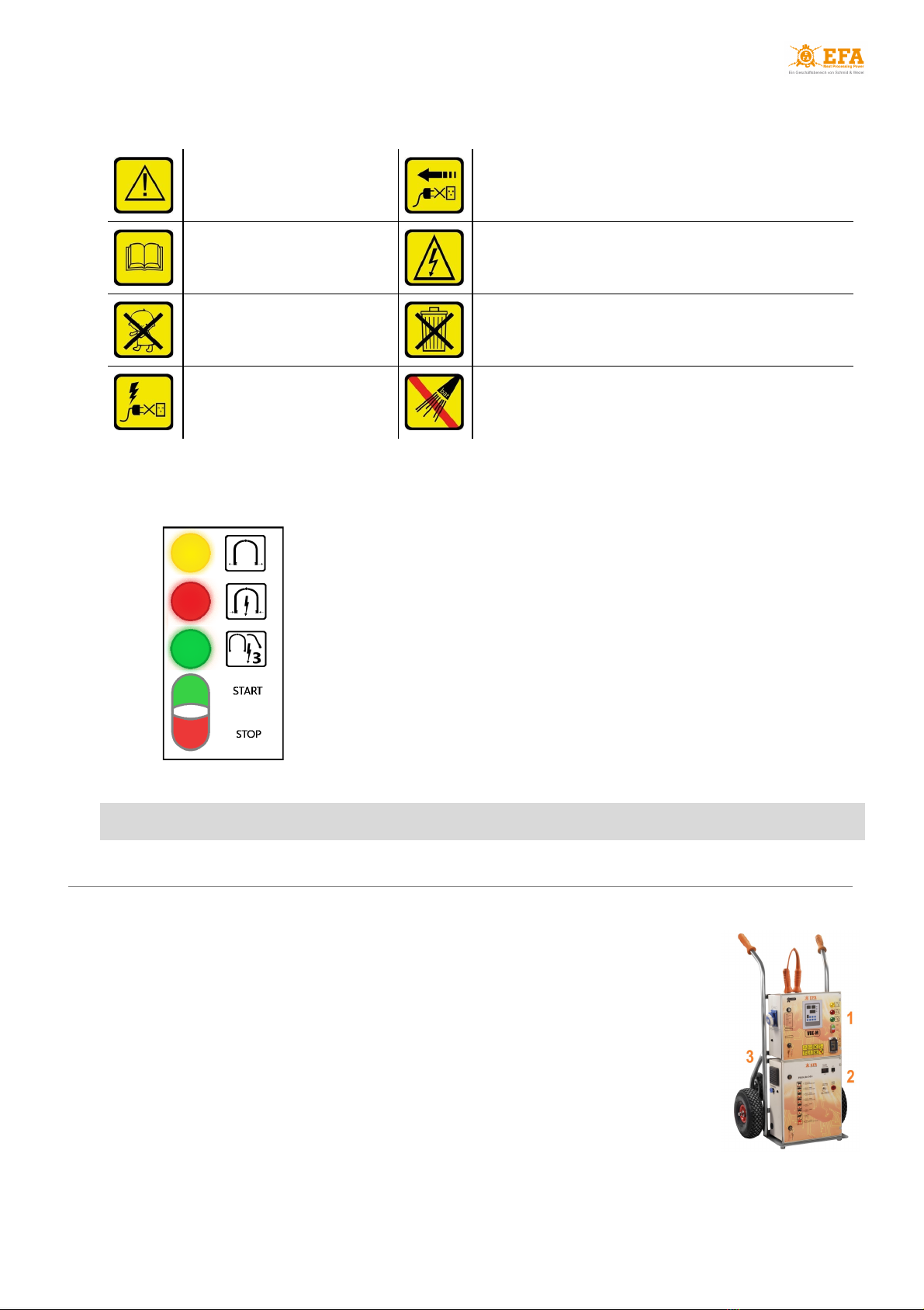
4.3 Signal lights
The device housing door is sealed. Breaking the seals will void the warranty
Caution
Any repairs, maintenance or technical service must be
carried out after disconnecting the device from the mains –
pull out the plug from the socket
Read the user manual
Do not touch! Dangerous voltage
Must not be used by minors
This device is recyclable. It is subject to the selective
collection of electrical and electronic equipment
Do not connect the device to the
mains if the connection or socket
is damaged
Do not wash with pressure washers
Fig. 2 Signal lights
● yellow light - END OF STUNNING
● red light - STUNNING
● green light - HEART STUNNING
● main switch - START/STOP
5. DESIGN, TECHNICAL DATA AND PARTS LIST
Equipment of the VBE-M device:
1. VBE-M stunning unit;
2. power system;
3. trolley with tongs cover.
The VBE-M stunning unit (1) and the power system (2) are permanently
attached to the trolley (3).
The trolley is equipped with additional wheels for transporting the device up the
stairs.
On the side of the VBE-M device housing (1) there are:
● oblique socket for connecting the tongs;
● PC connection socket.
On the side of the power system housing (2) there is a mains connection socket.

Mobile animal stunning device VBE-M
7
Detailed technical data and a list of components of the device can be found in:
●Specification - see: Appendix 2 ;
●Parts list - see: Appendix 3 .
5.1 Types of tongs
Table 3 Types of animal stunning tongs
CAUTION!
Before inserting, removing and when transporting (in the trolley) tongs connected to the
VBE-M stunning unit (1), turn off the VBE-M unit (1) using the STOP on the START/STOP
main switch (see Fig. 2 ).
X
XO
XP
YP
6. INTENDED USE AND PRINCIPLE OF OPERATION
The device is intended for pre-slaughter stunning animals using electric current with voltage lower
than 400 V and frequency in the range of 50-800 Hz.
The device must be used only for its intended purpose
The main controller of the device operates in 4 modes:
●boot mode - after turning on. The device checks all settings and prepares for operating;
●readiness for operation mode - the device has been properly turned on and is ready for use;
●stunning mode - the device measures the animal's resistance, starts the stunning process
and maintains the set parameters;
●programming mode - is used to set parameters (general and for selected programs). The
user can change the parameters of the selected program depending on the type, species and
size of the animal. Editing parameters - see: section 9.2 .
The device works according to the selected program with specific stunning parameters.
The display [Prog] shows selected program - it can be changed using the button.
The preset stunning programs can be found on the SDHC card:
● path to file: SD card/English/Parameters/ pigpar3.bin
The stunning voltage strictly depends on the animal’s resistance. The resistance depends on the
type, weight of the animal and method of electrode application. The device measures the
resistance and adjusts the voltage to obtain the required stunning current. Table 4 shows the
minimum current required ( Regulation 1099/2009 ):

Mobile animal stunning device VBE-M
8
Table 4 Minimum current depending on the type of animal
Type of animal
Minimum current [A]
sheep, goats, calves
1.0
lambs
0.6
pigs
1.3
cattle <6 months ÷ >6 months
1.25 ÷ 1.28
7. MAIN CONTROLLER
7.1 Control panel - buttons, indicators and displays
Table 5 Description of the control panel
The control panel is used to change the following stunning program values:
● current [A];
● frequency [Hz];
● stunning duration [s].
The control panel also allows to:
● define new stunning programs;
● set current date and time.
Fig. 4 Control panel
Buttons
selecting between parameters / parameter values
enter (confirm)
escape (exit)
switching the stunning program
changing the value on the display [V] from voltage to
frequency and back
service button
Signaling indicators
Displays in readiness for operation and stunning modes
[Alarm]
no SDHC card
[Prog]
stunning program number
[Pgm]
programming mode
[A]
current [A]
[HV]
high voltage on the electrodes
[C]
duration [s]
[Proc]
inactive
[V]
voltage [V] / frequency [Hz] - change with button
Displays in programming mode
[A]+[C]
name of the edited parameter
[V]
value of the edited parameter
[Prog]
number of the edited program

Mobile animal stunning device VBE-M
9
7.2 Main controller parameters that can be reprogrammed
Parameter available after entering the programming mode
Cd - access code , allows access to other parameters
General parameters
Lc - allows setting the access code:
●0 - no access code (all other parameters are visible without entering the access code);
● any value other than 0 activates the Cd parameter (entering the other parameters will be
possible after entering this value);
●5 - factory set access code.
tSG - does not apply to VBE-M
YEAr - setting the date (year)
Mon - setting the date (month)
dAY - setting the date (day)
Hour - setting the time (hours)
Min - setting the time (minutes)
SEc - setting the time (seconds)
toFH [s] - does not apply to VBE-M
Pr - allows to select the stunning program
Parameters of the selected stunning program
toFF [s] - pause between subsequent stuns (delay time between the stunning current decay and the
end of the stunning process
dL1 [s] - phase 1 - duration of stunning phase 1 (cannot be shorter than 1.0 s)
Fr1b [Hz] - initial frequency of stunning phase 1
Fr1E [Hz] - end frequency of stunning phase 1. The frequency changes from Fr1b to Fr1E over the
duration of dL1
SP1b [A] - initial current of stunning phase 1

Mobile animal stunning device VBE-M
10
Table 6 Description of the controller parameters that can be reprogrammed
SP1E [A] - end current of stunning phase 1. The current changes fluently from SP1b to SP1E over
the duration of dL1
tP1 - stunning mode 1 - determines the stunning mode in phase 1 (dL1) - detailed description:
section 7.3
dL2 [s] - phase 2 - duration of stunning phase 2. Setting dL2 to 0 cancels this phase. The following
parameters will then disappear from the menu: Fr2b; Fr2E; SP2b; SP2E; tP2
Fr2b [Hz] - initial frequency of stunning phase 2. The frequency jumps from Fr1E
Fr2E [Hz] - end frequency of stunning phase 2. The frequency changes from Fr2b to Fr2E over the
duration of dL2
SP2b [A] - initial current of stunning phase 2. The current jumps from SP1E
SP2E [A] - end current of stunning phase 2. The current changes fluently from SP2b to SP2E over
the duration of dL2
tP2 - stunning mode 2 - determines the stunning mode in phase 2 (dL2) - detailed description:
section 7.3
dL3 [s] - phase 3 - duration of stunning phase 3. Setting dL3 to 0 cancels this phase. The following
parameters will then disappear from the menu: Fr3b; Fr3E; SP3b; SP3E; tP3
Fr3b [Hz] - initial frequency of stunning phase 3. The frequency jumps from Fr2E. If dL2=0, the
frequency jumps from Fr1E
Fr3E [Hz] - end frequency of stunning phase 3. The frequency changes from Fr3b to Fr3E over the
duration of dL3
SP3b [A] - initial current of stunning phase 3. The current jumps from SP2E. If dL2=0, the current
jumps from SP1E
SP3E [A] - end current of stunning phase 3. The current changes fluently from SP3b to SP3E over
the duration of dL3
tP3 - stunning mode 3 - determines the stunning mode in phase 3 (dL3) - detailed description:
section 7.3
SPt [s] - duration counted from the beginning of the stunning process. After reaching the set value,
the end of the stunning process will be signalled (the yellow light and the sound alarm turn on) - it
means that the electrodes should be removed from the animal's body
EnHV – activation of selected stunning program :
●0 - inactive ;
●1 - active - measuring voltage on electrodes (stunning process starts automatically after
pressing electrodes to the animal's body );
●2 - does not apply to VBE-M;
●3 - does not apply to VBE-M.

Mobile animal stunning device VBE-M
11
7.3 Description of parameters tP1, tP2 and tP3 - stunning modes
Stunning modes tP1 , tP2 and tP3 define how the stunning process takes place in the individual
stunning phases ( dL1 , dL2 , dL3 ).
Possible variants of setting parameters tP1 , tP2 and tP3 :
● 0 - head, sinusoidal waveform ;
● 1 - head, rectangular waveform ;
● 4 - head-heart , sinusoidal waveform , continuation of stunning after the transition phase ;
● 5 - head-heart , rectangular waveform , continuation of stunning after the transition phase ;
● 12 - head-heart , sinusoidal waveform , suspension of stunning after the transition phase ;
● 13 - head-heart , rectangular waveform , suspension of stunning after the transition phase .
The other values of the parameters tP1 , tP2 and tP3 (2, 3, 6, 7, 8, 9, 10, 11) are inactive.
The rectangular waveform allows for stunning with higher current but the frequency is limited to 250
Hz.
Stunning modes:
●continuous mode - head :
Diagram 1 Current intensity diagram - continuous stunning
- for each phase ( dL1 , dL2 , dL3 ) parameters tP1 , tP2 and tP3 should be set to 0 or 1 ;
●two-stage mode - head-heart :
Diagram 2 Current intensity diagram - stunning with continuation in the transition phase

Mobile animal stunning device VBE-M
12
Diagram 3 Current intensity diagram - stunning with suspension after the transition phase
- one of phases ( dL1 , dL2 ) should be set as transition phase - the tP* parameter for this
phase should be set to 4 , 5 , 12 or 13 (depending on the selected course of the stunning
process);
- after applying the electrodes to the animal's head, the device starts STAGE I of stunning
( head )
- after the transition phase is over, a light signal (yellow lamp) and a sound signal will
indicate the moment when the electrodes should be removed from the animal's head (the
signal will turn off when the electrodes are removed from the head):
- for tP* = 4 or 5 after the transition phase is over, the device continues the stunning,
maintaining the values from the end of the transition phase - after removing the electrodes
from the animal's head, the device goes into the standby mode (the stunning is stopped);
-for tP* = 12 or 13 after the transition phase is over, the device suspends the stunning, the
measuring voltage appears on the electrodes - after removing the electrodes from the animal's
head, the device goes into the standby mode ;
- when the green light turns on, STAGE II of stunning ( head-heart ) can be started.
CAUTION!
After entering the standby mode , the device waits up to 10 seconds for the
re-application of the electrodes to the animal's body and for the start of STAGE II of
stunning - the application of the electrodes after the specified time will be registered as
stunning of the next piece (the stunning process will start from the beginning).
8. INSTALLING AND TURNING THE DEVICE ON
8.1 Turning the device on
CAUTION!
Operation of the device in high air humidity or during rainfall is inadvisable.
The main START / STOP switch of the VBE-M stunning unit and the main switch of the power system
should always be visible and accessible to the operator.
The device operates in two modes:
1. battery mode - when the device is not connected to the mains - VBE-M the device uses
battery power;
2. mains mode - when the device is connected to the mains - VBE-M the device uses mains
power and the battery is charged.

Mobile animal stunning device VBE-M
13
Switching between modes takes place automatically after connecting the power system to the
mains or disconnecting it.
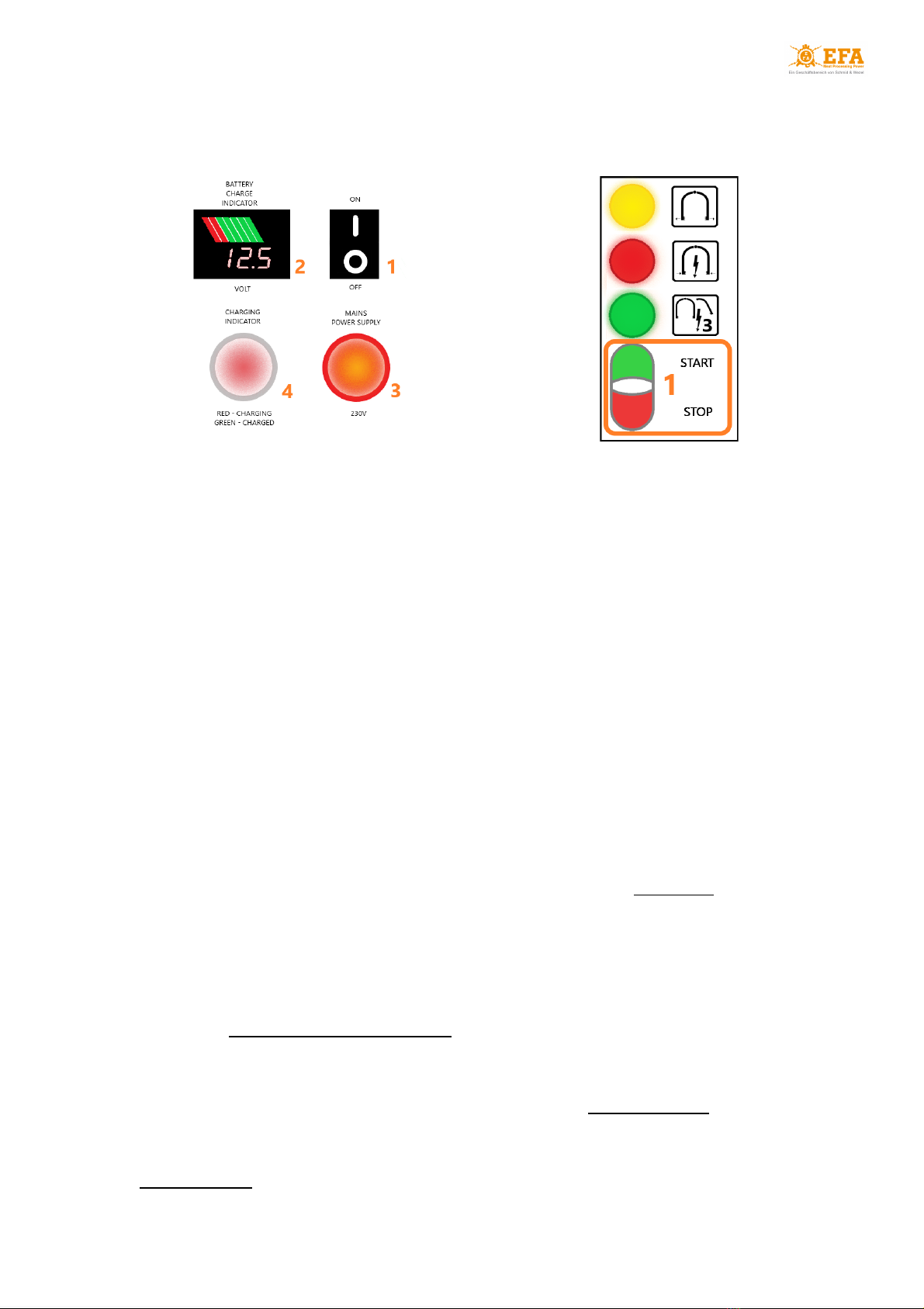
Operation in battery mode:
1. Turn on the power system using the ON / OFF switch located on the housing ( Fig. 5 pos. 1 );
2. After about 10 seconds, turn on the VBE-M using the START button ( Fig. 6 pos. 1 ) - the
device will automatically enter the readiness for operation mode ;
3. Fig. 5 pos. 3 - mains supply light is off;
4. Fig. 5 pos. 4 - battery charging light is off;
5. Fig. 5 pos. 2 - voltmeter shows the battery charge level.
CAUTION!
If during stunning in battery mode the battery charge level drops below green ( Fig. 5
pos. 2 ), it means that the battery is discharged to more than 50%. Then you should stop
stunning and connect the device to the mains in order to charge the battery. During the
stunning process, the battery voltage will drop.
Battery charging:
After connecting the device to the mains, the process of charging the power system battery begins.
The process takes place in 3 stages:
CAUTION!
Do not discharge the battery below 50% as this may damage it.
If the battery is 100% charged, about 100 stunning processes can be carried out (with 2A
current for 20s) - the actual number of stunning processes depends on the set stunning parameters
and may differ from the estimated one.
Fig. 5 Power system - battery mode
Fig. 6 VBE-M
Stage 1 - battery charging with 10A
direct current;
Stage 2 - battery charging with
constant voltage of 14.5V (14.3V -
14.7V);
Stage 3 - recharging the battery in
the range of 500-900 mA.
Diagram 4 Battery charging
Mobile animal stunning device VBE-M
14
The battery charging time from 50 to 100% is approximately 8 hours.
Operation in mains mode:
The device is equipped with a detachable power cord with a plug, which must be connected to the
power system and to the 230 V mains. The cord must not be within reach of animals or be exposed
to damage.
1. Using a detachable power cord, connect the power system to an electrical outlet protected by a
10 A fuse against short circuit and overload;
2. Turn on the power system using the ON / OFF switch located on the housing ( Fig. 7 pos. 1 );
3. Turn on the VBE-M using the START button ( Fig. 8 pos. 1 ) - the device will automatically enter
the readiness for operation mode (the device uses mains power);
4. Fig. 7 pos. 3 - the light indicating the mains supply is on - it means that the VBE-M stunning
unit is powered from the mains and not from the power system;
5. Fig. 7 pos. 4 - the light indicating the battery charging is on:
- steady red light - battery charging;
- flashing red-green light - battery charged (recharging in the range of 500-900 mA);
- steady green light - battery charged.
6. Fig. 7 pos. 2 - the voltmeter shows the battery charging voltage.
8.2 Starting the device
The device should be turned on in accordance with section 8.1 , depending on the selected
operating mode. The VBE-M stunning unit will automatically enter the boot mode :
● displays [A][C] , [V] and [Prog] will start blinking for about 2 s indicating the software version
and stunning program number;
● for the next 2 s all displays will show 8 ;
● next:
- displays [A] and [C] will show 0.0 ;
- display [V] will show the measuring voltage.
The device is in readiness for operation mode .
8.3 The course of the stunning process
For each of the programs on the device, you can set one of two stunning modes :
●continuous mode - head
●two-stage mode - head-heart
The stunning mode is determined by the parameters tP1 , tP2 and tP3 - see: section 7.3.
Fig. 7 Power system - mains mode
Fig. 8 VBE-M

Mobile animal stunning device VBE-M
15
The length of the stunning process is determined by the parameters:
●SPt - stunning duration - the time after which the alarm signaling the end of the stunning process is
activated - the electrodes can be removed from the animal's head;
●dL1 + dL2 + dL3 - sum of phase durations ;
If the sum of phase durations is greater than the stunning duration ( SPt ), the stunning process
continues until the electrodes are removed from the animal's head or the sum of phase durations
ends - see: Diagram 1 .
CONTINUOUS MODE - head :
Before starting the stunning process, only the measuring voltage occurs on the electrodes.
1. After pressing the electrodes to the animal’s head the device will enter the stunning mode . The
stunning process will start automatically:
The control system will give stunning voltage – the red light (STUNNING) will turn on:
● display [A] will show the stunning current;
● display [C] will show the duration [s] counted from the beginning of the stunning process;
● display [V] will show the stunning voltage.
2. After reaching the stunning duration ( SPt ) or the sum of phase durations the yellow light
(END OF STUNNING) and the sound alarm will turn on - see: Diagram 1 :
Remove the electrodes from the animal’s head
After reaching the stunning duration ( SPt ), the stunning process continues until the
electrodes are removed from the animal's head or until the sum of phase durations is
complete.
The end of the process will be signaled by the red light (STUNNING) turning off.
2. After removing the electrodes:
● the red light (STUNNING) and the yellow light (END OF STUNNING) will turn off;
● the sound alarm will turn off;
● display [A] will show 0 (no stunning current);
● display [C] will show the duration of last stunning process
● display [V] will show the measuring voltage on the electrodes.
3. After reaching the value set in the toFF parameter (pause between stunning) the device is in
readiness for operation mode again.
TWO-STAGE MODE - head-heart:
In the head-heart mode, one of the first stunning phases ( dL1 or dL2 ) should be set as the
transition phase - see: Diagram 2 and 3 .
Before starting the stunning process, only the measuring voltage occurs on the electrodes.
1. After pressing the electrodes to the animal’s head the device will enter the stunning mode . The
stunning STAGE I (head) will start automatically:
The control system will give stunning voltage – the red light (STUNNING) will turn on:
● display [A] will show the stunning current;
● display [C] will show the duration [s] counted from the beginning of the stunning process;
● display [V] will show the stunning voltage .
2. After the end of the transition phase ( dL1 or dL2 ), the device will signal the end of the
stunning STAGE I (head) - the yellow light (END OF STUNNING) and the sound alarm will turn
on.

Mobile animal stunning device VBE-M
16
Remove the electrodes from the animal’s head
● for tP=4 or 5 - the red light (STUNNING) will remain turned on - stunning will continue until
the electrodes are removed;
● for tP=12 or 13 - the red light (STUNNING) will turn off - the stunning will be suspended (the
measuring voltage will appear on the electrodes).
3. After removing the electrodes:
● the yellow light (END OF STUNNING) and the sound alarm will turn off;
● for tP=4 or 5 the red light (STUNNING) will turn off;
● the device will go into standby mode (see: Diagrams 2 and 3 ) - the green light (HEART
STUNNING) will turn on;
The maximum waiting time for reapplying the electrodes to the animal's body is 10 seconds
- after this time, the device will automatically end the stunning process and reapplying the
electrodes will start the next process.
4. To initiate the stunning STAGE II (heart), place one electrode between the animal's eye and
ear, and the other one in the heart area - the stunning process will resume automatically:
The control system will give stunning voltage – the red light (STUNNING) will turn on again:
● display [A] will show the stunning current;
● display [C] will show the duration [s] counted from the beginning of the stunning process;
● display [V] will show the stunning voltage.
5. After reaching the stunning duration ( SPt ) or the sum of phase durations the yellow light
(END OF STUNNING) and the sound alarm will turn on again - see: Diagram 2 and 3 .
Remove the electrodes from the animal’s body
After reaching the stunning duration ( SPt ), the stunning process continues until the
electrodes are removed from the animal's head or until the sum of phase durations is
complete.
The end of the process will be signaled by the red light (STUNNING) turning off.
6. After removing the electrodes:
● the red light (STUNNING) and the yellow light (END OF STUNNING) will turn off;
● the sound alarm will turn off;
● display [A] will show 0 (no stunning current);
● display [C] will show the duration of last stunning process
● display [V] will show the measuring voltage on the electrodes.
7. After reaching the value set in the toFF parameter (pause between stunning) the device is in
readiness for operation mode again.
Whenever the device is not used, turn off the VBE-M stunning unit using the STOP button on
the START / STOP main switch (see: Fig. 3) and the power system using the ON / OFF button
(see: Fig. 5, 7 pos. 1) . If the device is connected to the mains, disconnect it

Mobile animal stunning device VBE-M
17
9. MAIN CONTROLLER OPERATION
9.1 Unlocking parameters
1. To enter the menu press : the device will enter the programming mode
● the [Pgm] ( program ) indicator starts blinking;
● the display [A][C] shows blinking Cd letters;
● the display [V] shows 0 value.
2. Confirm by pressing :
● the display [V] shows blinking 0 value;
3. Using the buttons select 5 (factory code to unlock other parameters – it can be
changed by changing the value of Lc parameter).
4. Confirm by pressing :
● the Cd letters will start blinking again on the display [A][C] - it means that the parameters have
been unlocked and can be accessed by pressing the buttons.
9.2 Editing parameters
1. Unlock parameters: follow steps listed in subsection 9.1 .
2. Using the buttons select the general parameter Pr ( Program ):
● the Pr parameter allows you to select the program to be modified.
3. Confirm by pressing :
● the value on display [V] starts blinking;
4. Using the buttons select the program to be modified.
5. Confirm by pressing :
● the letters on display [A][C] start blinking
6. Using the buttons select the parameter to be modified (list of parameters: Table 5 subsection
7.2 ).
7. Confirm by pressing :
● the value on display [V] starts blinking;
8. Using the buttons select the needed parameter value.
9. Confirm changes by pressing :
● the letters on display [A][C] start blinking;
● you can similarly change other parameters starting from step 6.
10. Press to exit the programming mode .
9.3 Setting the date and time
1. Unlock parameters: follow steps listed in subsection 9.1 .
2. Using the buttons select the date/time parameter to be modified:
● the display [V] shows the current value of the selected parameter.
3. Confirm by pressing :
● the value on display [V] starts blinking;
4. Using the buttons select the needed parameter value.
5. Confirm changes by pressing :
● the letters on display [A][C] start blinking;

Mobile animal stunning device VBE-M
18
● you can similarly change other parameters starting from step 2.
6. Press to exit the programming mode .
10. STUNNING PARAMETER RECORDER
The device is factory-equipped with a recorder which measures electrical parameters and stores
the measured values on an SDHC memory card located in the recorder slot.
The recorder meets the requirements of the Regulation 1099/2009 (Appendix II point 4.1).
10.1 Parameter recording
Parameter recording begins when the stunning process is started - when the red light (STUNNING)
turns on. The stunning parameters are saved as text on the SDHC card, in a piglog.csv file.
Each line in the register refers to one stunning process. The values in the row are written in the
following order:
● subsequent number of the stunning process (it resets after turning the device off);
● stunning date in day-month-year format;
● the end time of the stunning process in hour-minutes-seconds format;
● average voltage [V] measured during the stunning process;
● maximum current [A] measured during the stunning process;
● electric charge [C] measured during the stunning process;
● duration of the stunning process [s];
● initial current frequency [Hz];
● program number;
● status:
M - too low stunning current (below the minimum value of 1.3A);
T - too short stunning time (below the minimum value of 4 s).
Table 7 Sample readings of stunning parameters
CAUTION!
The recorder battery can be replaced only by an authorized service center.
10.2 Parameter reading
To read the recorded data you must:
● remove the SDHC card from the slot on the device;
● insert the SDHC card into the SD card reader on your computer;
● open the piglog.csv file in any text file reader (e.g. Notepad) or spreadsheet (e.g. Excel).
Lp.
Date
Time
U[V]
I[A]
q[C]
t[sek]
f[Hz]
NrPgm
Status
1
11.05.2020
12:51:16
162
1.31
6.5
6.8
500
2
----
2
11.05.2020
12:52:11
161
1.32
6.5
6.8
500
2
----
3
11.05.2020
12:53:23
162
0.83
6.5
6.8
500
2
M---
4
11.05.2020
12:54:13
162
1.31
6.5
6.8
500
2
----
5
11.05.2020
12:54:52
162
1.31
6.5
1.2
500
2
--T-
6
11.05.2020
12:55:59
161
1.12
6.5
3.8
500
2
M-T-
7
11.05.2020
12:57:19
162
1.31
6.5
6.8
500
2
----
Mobile animal stunning device VBE-M
19
It is good to copy the piglog.csv file from time to time on your computer with a different name ( e.g .
May2021.csv ) and then delete it from the SDHC card. The recorder will create a new piglog.csv file during
the next stunning process .
Do not edit the piglog.csv file on the SDHC card - it may lead to registration errors
11. DOWNLOADING AND UPLOADING STUNNING PARAMETERS
The device comes equipped with the following functions:
● uploading parameters to the device from the SDHC card;
● downloading parameters from the device to the SDHC card.
To upload service parameters (factory settings) on the device:
● find the pigpar3.bin file with service parameters on SDHC card
(path to file: SD card/English/Parameters/ pigpar3.bin );
● copy the pigpar3.bin file to main directory of the SDHC card
(path to copied file: SD card/ pigpar3.bin );
●follow steps listed in subsection 11.1 .
To download your own parameter settings from the device to SDHC card (e.g. to transfer them to
another device) follow steps listed in subsection 11.2 .
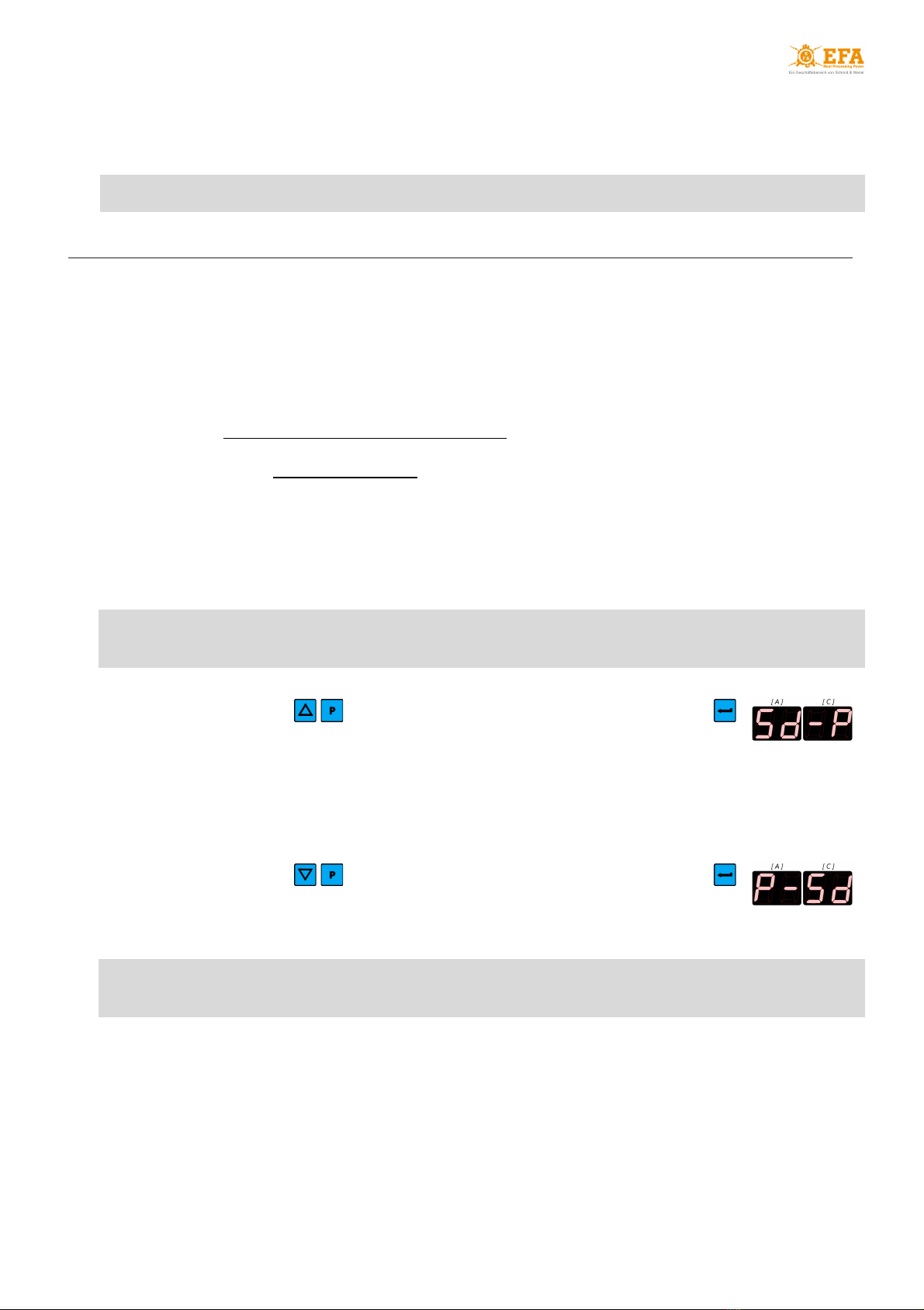
11.1 Uploading parameters to the device from the SDHC card
In order for the upload process to be successful, the pigpar3.bin file must be located in the main
directory of the SDHC card
● insert the SDHC card with pigpar3.bin file in the SD card slot (in the inspection window);
● press simultaneously buttons and without releasing them press and hold
until display [A][C] shows Sd-P :
- the parameters are correctly uploaded to the device from the SDHC card.
● release all buttons.
11.2 Downloading parameters from the device to the SDHC card
● insert the SDHC card in the SD card slot (in the inspection window);
● press simultaneously buttons and without releasing them press and hold
until display [A][C] shows P-Sd :
- the parameters are correctly downloaded from the device to the SDHC card
● release all buttons.
If the file named pigpar3.bin already exists in the main directory of the SDHC card, it will be
replaced by a new file

Mobile animal stunning device VBE-M
20
12. CONNECTING THE VBE-M DEVICE TO A PC
To enable communication of the VBE-M with the PC, install:
● USB converter drivers - ADAUSBDrv directory;
● EFA software for VBE-M - PC communication - PC directory.
Directories with installation files are in the main directory of the SDHC card - see: section 3 .
12.1 Installation of the USB converter drivers
STEP 1
Open the ADAUSBDrv folder and run ADAUSBDrv.exe
STEP 2
Select the installation language and press OK
STEP 3
Follow the on-screen instructions
1
2
3
This manual suits for next models
1
Table of contents
Popular Farm Equipment manuals by other brands

Kubota
Kubota AP-TC2536 Operator's manual

horsch
horsch Tiger MT Operation manual

Finn
Finn HydroSeeder TITAN280 Operator Instructions And Parts Manual

MacDon
MacDon R113 Unloading and assembly instructions

Worksaver
Worksaver UBH-2072R Owner's/operator's manual

RUGGED RANCH
RUGGED RANCH 44955 Assembly instructions


