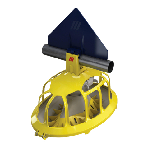
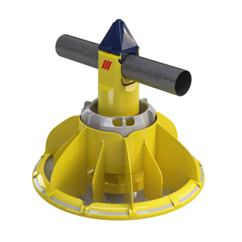
Roxell Optimax User manual

ROXELL - 004 - 4215OPTIMAX - TABLE OF CONTENTS
TABLE OF CONTENTS
CONTENTS
GENERAL INFORMATION
PART I : INSTRUCTIONS FOR THE USER
GENERAL SAFETY RULES I-3.......................................................
DIRECTIONS FOR OPERATING THE SYSTEM I-4.....................................
- PUTTING THE SYSTEM INTO USE I-4..........................................................
- PRACTICAL DATA FOR USING THE SYSTEM. I-4................................................
- PROGRAMMED FEEDING I-5..................................................................
- USE OF OPTIMAX AND OPTIMAX STARTPAN I-5................................................
- DIRECTIONS FOR USE OF THE ANTIPERCH WIRE I-5............................................
-WHENSTARTINGANEWFLOCK: I-6..........................................................
MAINTENANCE I-7.................................................................
MAINTENANCE INSTRUCTIONS I-8.................................................
TROUBLE SHOOTING GUIDE I-9/10....................................................
OPERATORS GUIDE I-11/12............................................................
DECLARATION OF INCORPORATION OF PARTLY COMPLETED MACHINERY
EC-DECLARATION OF CONFORMITY
PART II : COMPONENTS
GENERAL LAY-OUT II-2............................................................
PRODUCT NUMBERS II-3...........................................................
PARTS OPTIMAX PAN II-4...........................................................
OPTION : PAN REMOVER II-4........................................................
SUSPENSION COMPONENTS II-5....................................................
HAND OPERATED CENTRAL WINCH II-6.............................................
MOUNTING PLATE F/HAND OPERATED CENTRAL WINCH II-6.........................
TELESCOPICAL WINCH DRIVE ASSEMBLY II-6.......................................
SINGLE EYE PULLEY II-7............................................................
HEAVY DUTY PULLEY II-7...........................................................
FEEDER LINE COMPONENTS II-8....................................................
OPTION : AUGER INJECTOR KIT II-8.................................................
MOTOR II-9........................................................................
WINCH W/SWITCH + CP - MOTOR OPERATED II-9....................................
STANDARD : CONTROL SWITCH FOR WINCH II-9.....................................
WINCH W/SWITCH - MOTOR OPERATED II-10.........................................
OPTION : CONTROL PANEL FOR CENTRAL WINCH II-10................................
OPTION: CONTROL SWITCH FOR WINCH II-10.........................................
FEED INTAKE BOOT II-11............................................................
POULTRY INTAKE BOOT WITH SENSOR (OPTION) II-12................................
CANNON BALL (OPTION) II-13........................................................
THUMPER ASSEMBLY (OPTION) II-13.................................................
OPTION : DOUBLE FEED INTAKE BOOT II-13..........................................
THUMPER KIT FOR DOUBLE INTAKE BOOT(OPTION) II-14..............................
DOUBLE POULTRY INTAKE BOOT W/SENSOR (OPTION) II-14...........................
COVER HALF FOR 100KG HOPPER II-15..............................................
100KG HOPPER II-15.................................................................
STRAINER FOR 100KG HOPPER II-16.................................................
HOPPER EXTENSION 50KG II-16.....................................................
PARTS FOR ADJUSTING THE FEED LEVEL TUBES II-16................................
WINCH KIT II-16.....................................................................
POWER UNIT II-17...................................................................
CONTROL UNIT WITHOUT PAN II-18/19..................................................
CONTROL UNIT OPTIMAX WITHOUT PAN II-20/21.........................................
OPTION : INTERMEDIATE CONTROL UNIT WITHOUT PAN II-22/23..........................
OPTION : CONTROL UNIT WITH SENSOR - WITHOUT PAN II-24/25.........................
ROXELL - 004 - 4215 OPTIMAX - TABLE OF CONTENTS
OPTION : INTERMEDIATE CONTROL UNIT WITH SENSOR - WITHOUT PAN II-26/27..........
CUT-OFF SWITCH II-28..............................................................
CONTROL PANEL WITH TIME CLOCK II-29.............................................
THUMPER KIT FOR DOUBLE INTAKE BOOT(OPTION) II-29..............................
SPARES SET BEAR.CAP HOLD - Ø44.5 II-30...........................................
PART III : INSTALLATION INSTRUCTIONS
GENERAL SAFETY RULES III-1.......................................................
GENERAL LAY-OUT III-2.............................................................
COMPONENT NUMBERS III-3........................................................
TOOLS III-4.........................................................................
INSTALLING THE FEEDER PAN (WITHOUT WINCHING UP SYSTEM) III-5/7................
TO INSTALL THE FEEDER LINE III-8..................................................
TO INSTALL THE INTERMEDIATE CONTROL (OPTION) III-8.............................
TO INSTALL THE CONTROL UNIT III-9................................................
TO INSTALL AND SUSPEND THE 100KG HOPPER III-10.................................
SUSPENSION III-11...................................................................
SUSPENSION FOR FEEDER LINE III-12................................................
CENTRAL WINCH INSTALLATION III-13................................................
TO INSTALL THE MAIN CABLE III-14/15...................................................
DRAWINGS OF SUSPENSION SYSTEM WITH CENTRAL WINCH III-16....................
FEEDER LINE SUSPENSION III-17.....................................................
POWER UNIT SUSPENSION III-17.....................................................
TO INSTALL THE TELESCOPICAL TUBE III-18..........................................
TO INSTALL THE AUGER III-19/21........................................................
TO INSTALL THE THUMPER (OPTION) III-21............................................
OPTIONAL : SYSTEM WITH WINCHABLE TELESCOPICAL TUBES III-22...................
TO ASSEMBLE THE PAN WHEN USING A WINCHING SYSTEM III-23......................
TO INSTALL THE POULTRY PERCH GUARD III-24/25.......................................
ELECTRICITY .... WATCH OUT ! III-26..................................................
ELECTRICAL SYMBOLS III-27.........................................................
WIRING DIAGRAM FOR SINGLE PHASE MOTORS III-28.................................
WIRING DIAGRAM FOR THREE PHASE MOTORS III-28..................................
GENERAL CONNECTION DIAGRAM (SINGLE PHASE) III-29..............................
GENERAL CONNECTION DIAGRAM (THREE PHASE) III-30..............................
CONNECTION & WIRING DIAGRAM OF THE WINCH MOTOR (SINGLE PHASE) III-31.......
ELECTRICAL CONNECTION OF THE WINCH MOTOR (3-PHASE) III-32....................
OPTION : TO INSTALL THE AUGER BY MEANS OF THE AUGER INJECTOR III-33..........
MOTOR PROTECTION III-34...........................................................
MAXIMUM CABLE LENGTHS TO THE MOTORS III-35/36....................................
GENERAL TERMS AND CONDITIONS OF SALE

ROXELL - 2313
DISCLAIMER :Theoriginal,authoritative versionof thismanual is the English version producedby
ROXELLbvba.Subsequentchangestoanymanualmadebyanythirdpartyhavenotbeenreviewednorauthenticatedby
Roxell. Such changes may include, but are not limited to, translation into languages other than English, and additions to or
deletionsfromtheoriginalcontent.Roxelldisclaimsresponsibilityforanyandalldamages,injuries,warrantyclaimsand/or
anyotherclaimsassociatedwithsuchchanges,inasmuchassuchchangesresultincontentthatisdifferentfromtheauthoritat-
iveRoxell--published English versionofthemanual.For current productinstallationand operation information, please con-
tactthecustomerserviceand/ortechnicalservicedepartmentsofRoxell.Shouldyouobserveanyquestionablecontentinany
manual, please notify Roxell immediately in writing to: ROXELL bvba -- Industrielaan 13, 9990 Maldegem -- Belgium.

ROXELL - 0516
GENERAL INFORMATION
THESE INSTRUCTIONS MUST BE READ, UNDERSTOOD AND ALL POINTS OBSERVED BY THE
USER, THE RESPONSIBLE AND OPERATING PERSONNEL.
1. OBEY THE LEGAL REGULATIONS AND THE APPLICABLE RULES!
This concerns, among other things, the European directives transposed into national legislation and/or the laws,
safety and accident prevention regulations that apply in the user's country.
During assembly, operation and maintenance of the installation the legal regulations concerned and the applicable
technical rules must be obeyed.
2. INTENDED USE
The installation has been designed solely for intensive livestock use and has been developed according to the ap-
plicable rules of good workmanship. Extra loading of the product istherefore prohibited.Any other use is considered
to be improper use. The manufacturer is not responsible for damage resulting there from. The user bears sole re-
sponsibility.
3. NOT-INTENDED USE
All use different than described in point 2” intended use” is at the responsibility of the end user.
4. LIABILITY
The (Extended) Warranty will not apply if any of the following has occurred: failure to conduct incoming goods
inspection with regards to the Products, improper handling, transportation, modification or repair; accident, abuse
or improper use; improper assembly, installation, connection or maintenance (having regard to Roxell’s most
current assembly, installation, connection and maintenance manuals); force majeure; negligence, lack of
supervision or of maintenance on the part of customer; normal wear and tear; use of cleansing agents and
disinfectants that are excluded in Roxell’s most current use and maintenance manuals; use of cleansing agents and
disinfectants in violation with the instructions received from the suppliers; or use of the Products in an ATEX-
surrounding.
The (Extended) Warranty shall not apply in the event of adefect caused either by materials or accessories supplied
by or services rendered by Customer; or by an intervention by a person or entity which is not authorised or qualified
for carrying out such intervention. Furthermore, the (Extended) Warranty will only apply if the Products are used in
livestock houses and if all parts or components of the Products are supplied by Roxell.
Roxell will not be liable for any damages caused due to improper use, assembly, installation, connection or
maintenance of the Products. In this respect, the Customer expressly acknowledges that (i) all use, assembly,
installation, connection or maintenance must be donein accordance with Roxell’s most current assembly,
installation, connection and maintenance manuals and (ii) the electrical installation on which the Products must be
connected must be done in accordance with applicable local legislation on electrical installations. Furthermore, the
Products must be tested both mechanically and electrically in accordance with state of the art techniques and
applicable local legislation.
5. PERSONNEL QUALIFICATIONS
USER:
The person who uses a function or operation of a product for their work or who works on the product. The user must
be able to read the instructions for use and fully understand them. The user has knowledge of the functioning and
construction of the installation.
TECHNICALLY TRAINED PERSON:
An expert who can assemble and maintain the installation (mechanically/electrically), and resolve malfunctions.
Onthebasisofhis/hertechnicaltrainingandexperience, he/shehassufficientknowledgetobe able to assessactiv-
ities, recognise possible dangers and rectify dangerous situations.

ROXELL - 0516
6. INFORMATION ABOUT THE RESIDUAL RISKS - USED SAFETY SIGNS
There are three levels of danger, which you can recognize from the signal word
* DANGER
* WARNING
* CAUTION
The nature and source of the imminent danger and possible consequences of not obeying warnings is stated here!
DANGER
DANGER indicates a direct imminent dange
r
that can result in a serious or even
fatal accident if the safety measures are not respected.
WARNING
WARNING indicates a possible imminent danger that can result in a serious acci-
dent or damage to the product if the safety measures are not respected.
CAUTION
CAUTIONindicates possible, dangerous situations that can result in minor physical
injury or material damage if the safety measures are not respected.
This symbol refers to supporting information.
not allowed
allowed
7. STORAGE
Put all parts to be assembled in a room or at a location where the not yet assembled components are protected
against weather influences.
8. TRANSPORT
Depending on the size of the parts and according to local circumstances and local legislation, the parts of the ma-
chine have to be transported with a forklift.
The forklift must be operated by a qualified person and in accordance with the rules of good workmanship.
When lifting the load, always check if the center of gravity of the load is stable.

ROXELL - 0516
9. DISMANTLING
Dismantle the installation and its components in accordance with the environmental legislation of the country or the
local authorities applicable at that time. All functioning products and exchange parts must be stored and disposed of
in accordance with the applicable environmental regulations.
Environmental information for customers in the European Union
European directive 2002/96/EC amended by the Directive 2008/34/EC requires that equipment that
bears this symbol on the product or packaging must not be disposed of with unsorted household
waste. This symbol indicates that the product must be disposed of separately. Your are yourself re-
sponsible for the destruction of this and other electrical and electronic equipment via the disposal
channels designated for that purpose by the national or local government. The correct destruction
and recycling of this equipment prevents any negative consequences for theenvironment and health.
For more information about destroying your old equipment, contact your local authorities or waste
disposal service.
Information about waste disposal - electrical/electronic material for companies
1. In the European Union
If you have used the product for commercial purposes and you want to dispose of it,contact Roxell who will give you
information about the return of the product. It is possible that you will have to pay a disposal charge for the return and
recycling. Small products (and small quantities) can be processed by the local collection agencies.
2. In other countries outside the European Union
If you want to dispose of this product, contact the local authorities for information concerning the correct disposal
procedure.
10. THE LEVEL OF NOISE EMISSION
The noise level of the installation in operation does not exceed 70dB(A).
11. LOCK OUT TAG OUT – LOCK METHOD GENERAL
- Everyone needs his own lock and tag (label), which can’t be removed by other persons.
- Inform all persons who are influenced by the procedure.
- Localize all sources of energy (electric, hydraulic, pneumatic).
- Switch off.
- Lock out and tag out.
- Check if the source of energy is switched off.
- Remove any remaining energy.
12. USE PERSONAL PROTECTIVE EQUIPMENT.
Ensure you wear personal protective equipment (gloves, dust masks...).
13. SUFFICIENT LIGHTING - ILLUMINANCE
-A minimum illuminance of 200 lux is necessary during usage, maintenance and installation.
- Provide at the installation (portable) emergency lighting in case of power failure.
14. ELECTRICAL EQUIPMENT, CONTROL PANELS, COMPONENTS AND DRIVE
UNITS
- To operate control panels, there must be atleast70cmoffreespace.
- Control panels must always remain closed. The key of the control panel must be in possession of an au-
thorized person.
- The necessary measures must be taken by the user to keep out rats, mice and other vermin from the
control panels
- If electrical equipment, control panels, components and drive units are damaged, the system must be
stopped IMMEDIATELY!
- Electrical equipment, control panels, components and drive units should NEVER be sprayed with water or
other liquid!
- Electrical equipment, control panels, components and drive units should NEVER be covered with any ma-
terial.


I--1
PART I
INSTRUCTIONS FOR THE USER

OPTIMAX -- INSTRUCTIONS FOR THE USER ROXELL - 004 - 2111
I--2

ROXELL - 004 - 2111 OPTIMAX -- INSTRUCTIONS FOR THE USER
I--3
Multimax/Optimax Nr: 004...
Automatisch pannen voedersysteem voor opfok en productie van kalkoenen
Automatic pan feeding system for rearing and production of turkeys
GENERAL SAFETY RULES
1. Beforeyoudoanyrepair,ormaintenance works, always disconnect the electricity sup-
ply.
2. Ensure you wear personal protection equipment (gloves, dust masks).
3. The system starts automatically.
Never use your hands at dangerous locations (feed intake boots, drive units, control units
or outlet holes in the tubes) before you have completely switched off the transport system
and made sure that nobody can switch it on without your knowledge.
4. Never allow unauthorized persons to enter the house in your absence.
5. Be careful when lowering or winching up the feeding lines/circuits :
-stop immediately at the slightest hitch.
-never stay underneath when lowering or winching up the lines/circuit.
6. If the auger stalls : immediately switch off the system. Carefully read the trouble shooting
guide and strictly follow instructions. Contact a technically trained person.
An auger under tension can cause very serious injuries when released.
7. Regularly check the elbow/trough and/or tube connections. Tighten if necessary.
8. Ensure that the hopper cover (grill) or cover on the 100 kg hopper closes properly.
9. Regularly check that the control unit (pan) and/or the motor handy box are properly
closed.
IMPORTANT
Carefully read the following instructions before
USING the system
Winching systeem
Liersysteem voor voer- en drinklijnen
Winching system for feed- and drink lines
DANGER
This SYMBOL will be used to draw your attention to matters that are
of GREAT IMPORTANCE for your SAFETY.
It means : WARNING - follow the safety instructions :
disconnect the current - re-read the safety rules.
In short : BE ALERT.IGNORING these instructions can cause SE-
RIOUS INJURIES or even DEATH.

OPTIMAX -- INSTRUCTIONS FOR THE USER ROXELL - 004 - 2111
I--4
DIRECTIONS FOR OPERATING THE SYSTEM
PUTTING THE SYSTEM INTO USE
The oil on the new auger and the tubes will slow up feed
transport in the beginning.
When using a new feeder line for the first time, fill up the
feed intake boot with 25kgs of feed.
NEVER PUT YOUR HANDS INTO THE
FEED INTAKE BOOT WHILE FILLING
THE PANS.
Switchonthefeederuntilthisfeedisdistributed,thenrepeat
the procedure until the whole line is filled.
By doing this :
-- you limit the load on the motor of a long feeder line.
-- atthesametime,youtesttheswitchesandmakesurethat
the feeder line has been properly installed.
-- you become used to the system.
IMPORTANT : bring the house with the litter to the right
temperature at least 24 hours before you put the birds in.
Birds are sensitive to light, moisture, draught and tempera-
ture. They will shun places with an environment deviating
from the average.
The last feeder pan on the line (the control pan)isthemost
important one and it has to be properly adjusted (low feed
level : 1 1/2--2cm.
Itmustbeemptiedfirstbecauseitstartsthenextfeedsupply.
Takecare that thereareenoughbirdsfeeding from thispan.
Youcanhavemore lightabovethe controlpanbyinstalling
forexampleasmallspotlightwhichlightensthecontrolpan
only.
Keep the pan free of litter and manure. It has to be the most
attractive pan on the line.
Take care that temperature, moisture, ventilation are con-
stant at this location.
Morebirdswillfeedfromthecontrolpansifyouinstallthem
somewhat further away from the end wall (3--4m).
The same remark goes for the control pans of the outside
lines (next to the side walls).
Lay--out the feeder lines in such a way that the biggest dis-
tance between feed and birds is about the same for all lines
(L<4,5m).
Thefeederlinefurthestfromthebinisequippedwithalevel
switch (installed as low as possible) in the hopper.
This level switch controls the feed supply from the bin.
If,forcertainreasons,thelastlineisnotenoughusedbythe
birds, you must install a level switch in the other hoppers.
Take care to have a 100% drop out at each hopper switch.
Youcanhelptoensurethatenoughbirdseatfromthelastli-
ne by taking care over :
-- ventilation
-- house structure
-- insulation
-- litter
-- distribution of feeders and drinkers.
Whenplannedcorrectly,youwillhaveaveryevenspreadof
the birds over the whole floor area of the house.
PRACTICAL DATA FOR USING THE SYSTEM.
1. Theedgeofthefeederpanmustbeat a levelwhichcor-
responds to the spot where the bird’s back merges with
the neck.
Keeping the pans at the correct level will prevent birds
from scratching in the feed.
Pans are winched up gradually as birds grow.
Example : for birds weighing about 10kgs, the edges of
the feeder pans will be 40--45cm above floor level).
By keeping the pans at the correct level :
-- you limit feed waste
-- litter and dirt are kept out
-- birds can move easily between the lines.
2. Undernormalcircumstances,therewillbetheleastfeed
waste when the feed level in the pan is about 2cm.
Fordebeaked birds, you need a slightlyhigherfeedlev-
el.
The feed level can be very easily adjusted. Turn the ad-
juster ring in the desired position. Usually you can use
position 5--6.
You can also use winchable feed level tubes (option) if
you want to increase the feed level in the beginning of
the fattening period.
It is also possible to obtain manually a high feed level.
Lift the feed level tube and turn slightly to the right.
3. Thefeederlineforadultturkeyscanbeequippedwithan
intermediate controlinordertouseonlypartoftheline.
Advantage : a part of the house can be shut--off or emp-
tied to save labour, feed and energy.
4. Ifthebirdshavebeenwithoutfeedforaconsiderablepe-
riod,youmustbeverycarefulwhenfillingupthefeeder
lines.
Spread some feed on the litter so that the birds do not
rush onto the pans when the augers start.

ROXELL - 004 - 2111 OPTIMAX -- INSTRUCTIONS FOR THE USER
I--5
Walk along the lines and gently disperse birds.
Anothermethod:winch upthefeederlinesso thatbirds
can’treachthepans.Onlythenfillupthepansandlower
thelines:butmakesurethatbirdsdon’tpusheachother
under the pans as they are lowered.
Keep an eye on the feed supply.
5. The suspension cable of a new system always stretches
a little. Take care to have the (heavy) hopper well sus-
pended. If necessary, change one or more links.
PROGRAMMED FEEDING
Thismeans:feedingaccordingtoaprogrammesetonatime
clock.
WHY PROGRAMMING
Tomakesurethatnofeedissuppliedduringcertainperiods.
Pans are almost emptied between meals.
ADVANTAGES :
-- Better feed conversion :
* birds waste less feed (lower feed level)
* fresh feed available at several preset times = more
resting periods ; a better digestion ; more appetite.
* you can observe birds better during the meal. Sick
birds are more easily identified.
-- Thesystemoperatesmoreregularly;birdsassociatethe
noise of the running auger with fresh feed (Pavlov--ef-
fect).
-- You have better control of the system’s performance.
HOW TO PROGRAMME
There are many ways.
Thebestsystemistoprogrammeinsuchawaythatpansare
eaten just empty without causing any stress to the birds.
You can start programmed feeding ONLY AFTER 3
WEEKS when the animals are used to the system.
Occupation per pan and per drinker cannot exceed our re-
commendations.
Ifthereisa disease problem :stopprogramminganddonot
let the system run empty.
To get the maximum profit out of your system, you should
develop your own programme according to the circum-
stances.
For any further advice, contact ROXELL N.V.
USE OF OPTIMAX
Capacity : males & females from 5--7 weeks up till about
15kgs : 70 birds/pan.
If end weight deviates, adapt density.
1. SEPARATE REARING HOUSES.
WithMultimaxyoucanfeedturkeycocksandhensfrom
1 to 5--7 weeks. Automatic feeding from the first day.
Afterthat,thebirdsmovetoanotherhousewhereOPTI-
MAX is installed.
Malebirdsarefastergrowersandarethereforegrownon
standard OPTIMAX until they reach slaughter weight.
Femalebirdshoweveraresmaller and are killedsooner.
They are fattened on OPTIMAX with a winchable feed
level tube.
The feed level can be lowered gradually as the female
birds grow.
2. TWO HOUSE FARMS.
Thisgrowingmethodassurestheturkeygrowerofacon-
tinuous production.
Maleandfemalebirdsaregrowninthesamehouseuntil
5--7weeksofage,onMULTIMAX.Thenthemalebirds
move to another house where they continue on OPTI-
MAX until slaughter weight.
In the meantime, the females grow on MULTIMAX.
They are finished earlier (14 to 16 weeks) than the male
birds which grow heavier. After the rearing period, put
a collar on the Multimax--pan to prevent feed waste.
This enables thegrower to clean out the empty MULTI-
MAX--house after the females have been slaughtered.
Whilethemalebirdsintheotherhousearestillfattening
he can start again rearing males and females in the first
house, on MULTIMAX.
By the time the second house is empty and cleaned out,
a new batch of 7 week--old males is ready to move in.
3. REARING ON A ONE-HOUSE FARM.
Malesandhensaregrown(separately)inonehousewith
Optimax starter pan, with winching system for the feed
level rings (until 6--7 weeks.)
AtthatmomenttheOptimaxstarterpansarereplacedby
the standard Optimax feeder pan
At 14--15 weeks, the hens are removed for slaughter.
ThemaleturkeysusethewholehouseonOPTIMAXun-
til finishing.
After that, the cycle starts again.

OPTIMAX -- INSTRUCTIONS FOR THE USER ROXELL - 004 - 2111
I--6
4. USE OF OPTIMAX STARTER PAN
Management recommendation for use of the starter pan
MAX C with Optimax winching up system.
FIGURE 1. Max C
For ease of use : always install the starter pan with
winching system for telescopical tube.
FIGURE 2.
Set the feed level ring assembly always in position 10.
1ST WEEK
Set the feed level ring assembly in position 1.
Winchthefeedlevelringup,sothatthebottomsideisabout
1cm under the edge of trhe MAX C pan.
2ND WEEK
Lower the feed level ring 4 clicks of the winch.
3RD WEEK
Lower the telescopical tube an extra 2 clicks of the winch
4TH WEEK AND MORE :
Lowerthe telescopicaltube furthertoa minimum position.
DIRECTIONS FOR USE OF THE ANTIPERCH WIRE
The steel cables above the lines have a double function :
-- for one thing they bring the pans back into a horizontal
position by spring tension ;
-- for another they serve as antiperch wires under charge.
Soyoumusttightentheminsuchawaythattheydon’ttouch
the tubes unless birds perch on the line.
Earththefeedingsystembymeansofthewiringofthepow-
erunitorbymeansofaseparateearthconnection,sothatthe
antiperch system will properly function.
Theelectro--chargermustfunctiononaseparatecircuit.You
musthavethepossibilitytodisconnectitbyaswitchcloseto
the door so that birds stay calm when you enter the house.
WHEN STARTING A NEW FLOCK :
Check operation of your system before placing the birds.
More particularly, take care that :
-- all feed level tubes are at the same level (always keep
feed level as low as possible)
-- all switches and sensors react promptly
-- the control pans are properly adjusted (low feed level)
-- the antiperch wire is still stretched (springs must be
stretched 5--7cm.
-- there are no leaks in the feed supply system
-- there is no old, stale and/or tainted feed in the bin
-- thefeederlinesarewellaligned.Especiallythepower
unit and the hopper must be well aligned and at the
same level.

ROXELL - 004 - 2111 OPTIMAX -- INSTRUCTIONS FOR THE USER
I--7
MAINTENANCE
The feeding system for turkeys requires very little mainte-
nance.
When removing the birds from the house, take care not to
damage pans or other parts of the system (e.g. by machines
or heavy objects).
Alsoremovetheremainingfeed fromthepansand fromthe
hoppers. This will prevent corrosion during the time the
house is empty and during cleaning.
Winchupthelinesabout1m.Usethehingedpansupportsto
clean pans one after another by means of a high pressure
cleaner.
DON’T FORGET TO COVER UP THE CONTROL
PANWITHPLASTIC!
Motors and switches are protected IP55. This means that
they withstand a syringe, NOT a high pressure cleaner.
After cleaning, remove water from the pans and if possible
raise the house temperature so that pans dry quickly.
ATTENTION : SELECT YOUR DISINFECTANTS !
Disinfectantsbelowareextremelycorrosiveandcouldinno
time damage your system BEYOND REPAIR.
SO NEVER USE : gaseous formaldehyde, liquid caustic
soda or solution of caustic soda, hypochlorite or chlorine
water, cresoles.
WerecommendtouseonlyQUATERNARYAMMONIUM
COMPOUNDS ; COMBINATIONS OF FORMALDE-
HYDE, GLUTARALDEHYDE OR FORMALDEHYDE
WITH SOAPS.
AFTER DISINFECTING YOUR HOUSE, VENTI-
LATE LONG ENOUGH AND INTENSIVELY.

OPTIMAX - INSTRUCTIONS FOR THE USER ROXELL - 004 - 0715
I-8
MAINTENANCE INSTRUCTIONS
DANGER
Switch of
f
the main switch first.
Use personal protective equipment.
3-monthly
6-monthly
Yearly
ACTIONS IN GREY BACKGROUND MUST BE DONE BY A TECHNICALLY TRAINED PERSON.
1. Power unit
- Make fan dust-free X
- Check possible damages to electrical wiring X
2. Poultry intake boot with sensor
- Check sensor X
3. 100kg hopper (lines)
- Check level switch X
4. Suspension
- Check operation of (central) winch X
- Check operation of (central) winch. Grease after cleaning. X
- Check connection of cable X
- Check connection of pulleys X
- Check suspension of tubes and motors X
- Keep suspension cord/cable in tension X
5. Poultry perch cable above the tubes/elbows
- Check cable X
6. Pans
- Check possible damages of pans X
7. Sensors/switches
- Check operation of safety switch or sensor. X
- Check electrical wiring X
8. Control pan
- Remove the pan and clean the inside tube X
- Clean (dry) sensor head and central tube X
- Check switch of control units X
9. Lines/circuits
- Check screws and bolts in the system after the first month and after
each batch. Tighten if necessary. X
- Keep tubes level. X
- Remove all feed from the system when the system will be out of use for a
period. X

ROXELL - 004 - 0715 OPTIMAX - INSTRUCTIONS FOR THE USER
I-9
TROUBLE SHOOTING GUIDE
Switch off the main switch first.
Use personal protective equipment.
DANGER
ACTIONS IN GREY BACKGROUND MUST BE DONE BY A TECHNICALLY TRAINED PERSON.
PROBLEM CAUSE CORRECTIVE ACTION
1.None of the feeder
lines run. No current. Replace defective fuses or reset circuit breakers.
Check current supply to the house.
Defective time clock. Replace defective clock.
Time clock not properly set. Readjust tabs.
2.One/more lines do
not run.
Pans are empty
Wires from motor damaged. Measure current in motor wires. Replace wires if
defective.
Motor protection switched off. See points 3. & 4. Reset motor overload button.
Defective sensor in the control unit, or
sensor not properly adjusted. Check the good operation of the sensor.
Replace if necessary.
Control unit not functioning properly. Adjust level of control pan. Hang an extra lamp
above it. Check temperature. Control unit must be
the most attractive one, especially the control unit
of the feeder line below the Flex-Auger control unit.
Defective sensor/minimum switch
control unit or 100kg hopper. Check control unit sensor or switch. Replace if
necessary.
3.Motor is often
overloaded. Oil on auger overloads the motor. Clean the auger by running repeatedly 25kgs of
feed through the line.
Not enough current supply to the
motors. Check current supply at motor location. Start the
motor. Measure start current on motors. Wiring
must be thick enough to guarantee good operation
of the system.
Object blocks the auger. Motor runs,
then stalls. Feed sticks to the tubes. Check if there are no objects in the boot, the control
unit and the drop holes of the feeder pans. Remove
any objects.
4.Auger stalls. Anchor bearing worn out or broken. Replace bearing. Gently slide auger back into
thetubes.Don'tletitjumpback:yourfinger or
the bearing could be damaged.
Auger not enough stretched. Shorten the auger.
Object blocks the auger. Remove the object.
5.Tubes / boot wear
rapidly,
much noise when
system runs.
Auger kinked or bent at the wear
point.
Auger end overlaps the anchor end.
Make sure not to kink the auger when using
gripping pliers. Auger must not overlap the anchor
end.
6.Not enough feed
supplied to fill up
the lines.
Flex-Auger drop holes are too small
or point upwards. Make holes wider/turn tubes with holes
downwards.
Flow regulator in boot of feed supply
system blocks passage of the feed. Adjust flow regulator to get a higher capacity.
Flex-Auger capacity is too low. Check the capacity of the Flex-Auger according the
specifications.
Check the installation of the Flex-Auger.
Notenoughtimesetonthetimeclock. Extend operation time per meal.
7.Feed drops
directly on
the adjuster ring
of the grill.
Pan not installed over the hole. Remove the top support. Install the pan ass'y over
theholeandthelips.

OPTIMAX - INSTRUCTIONS FOR THE USER ROXELL - 004 - 0715
I-10
PROBLEM CAUSE CORRECTIVE ACTION
8.Hopper 1 is empty
while the feed
level in the
second hopper
corresponds with
the position of
the level switch
Birds massively move to one side of
the house, i.e. depending upon the
position of the sun.
A. The problem occurs sporadically :
You can solve the problem by changing the
round hole in the Flex-Auger tube above
hopper 1 into a rectangular one. Install two
outlet drops above hopper 1 (see fig. 3.) if
necessary, so that more feed drops into
hopper 1. Install the level switch low in hopper
2 (see fig. 2.). Install and adjust drop tubes to
all hoppers high enough.
B. The problem occurs regularly :
Installalevelswitchhighineachhopper.
Install the level switch low in the last hopper.
Install and adjust the drop tube high, so that
the feed in tube A (over switch level) is carried
to hopper 2.
Drop tube installed and
adjusted high.
Level switch installed
low.
Hopper 1
Hopper 2
FIGURE 1. FIGURE 2.
A
Hopper 2
Case a.
Large feed reserve (A) in
case b.
Hopper 1
FIGURE 3.

ROXELL - 004 - 4114 OPTIMAX - INSTRUCTIONS FOR THE USER
11
O
Optimax: Position
With
winching sys-
tem
Always 1
Winch up till 1cm
beneath the pan
edge.
Lower 4 clicks Lower 2 clicks Minimum position
Without
winching sys-
tem
9-10 3-4 1-2 Minimum position
4114 00403329
2-house system
Separate rearing farms
OPERATOR’S GUIDE
Forfloorfeedingforturkeysupto25kg.
Weeks
0123
Winch up
EASY START
AVOID FEED WASTAGE = ADJUST FEEDER HEIGHT
Lower
Winch up
1house
STARTER PAN
Max. 25 kg
OPTIMAX PAN
8 9
6-7
Age of birds

OPTIMAX -- INSTRUCTIONS FOR THE USER ROXELL - 004 - 2111
12
Number of birds per pan
Starter pan 60 70
Optimax 4050
Optimax 60 70
0511 00403329
(FIXED INTERMEDIATE) CONTROL PAN
For controlled feeding : have the pans emptied once (to several times) a day.
OPERATOR’S GUIDE
-- use from :
2 weeks (turkey chicks)
-- do not use it constantly
-- use as WARNING !
AVOID DRAUGHTS
(for partial brooding)
AVOID DARKNESS
* The last day : run the tubes empty and let the birds empty the pans as much as possible.
* Removepossiblefeedresidues byturningthe pansacouple oftimes 180degrees aroundthetubesor byremovingthepans
from the grills.
* Protect electrical components against water.
* Clean the whole system by means of a high--pressure cleaner (max. 100 Bar).
* When using aggressive detergents or disinfectants consult your supplier.
CLEANING
= THE MOST USED PAN
CHECK THE SUSPENSIONS OF THE 100 KG HOPPER AND THE
CONTROL UNIT AFTER HEATING UP THE BUILDING. BOTH SUS-
PENSIONS MUST BE WELL STRETCHED.
Poultry perch system
Table of contents
Other Roxell Farm Equipment manuals

Roxell
Roxell Vitoo In Line User manual

Roxell
Roxell SparkCup User manual

Roxell
Roxell CoMeo User manual

Roxell
Roxell Boozzter User manual

Roxell
Roxell Blu'Hox User manual

Roxell
Roxell Minimax Line User manual

Roxell
Roxell Discaflex User manual

Roxell
Roxell KiXoo in line User manual

Roxell
Roxell Bridolay User manual

Roxell
Roxell HaiKoo User manual