Horizont Agrar ranger A70 User manual

85304A - 02/13
horizont group gmbh
Division agrartechnik
Postfach 13 29
34483 Korbach
Homberger Weg 4-6
34497 Korbach
GERMANY
Telefon: +49 (0) 56 31 / 5 65-1 00
Telefax: +49 (0) 56 31 / 5 65-1 20
www.horizont.com
BETRIEBSANLEITUNG
Elektrozaungerät
de
OPERATING INSTRUCTION
Electric Fencer
en
MODE D‘EMPLOI
Électrificateur de Clôture
fr
ranger A70
Type 10852GPSD
12V DC
GPS SECURITY und SMS CONTROL
mit Zusatzmodule
with additional device
avec module supplémentaire

2 3
3
87926
89224
83403
84021D
GPS-Modul
84023
94581
89474
60188
60219
90764
97690
84719
88148
94581
97683
60688
97929
84741
89474
94581
90005
1
89976
Z2
Z1
90739
2
4
98271
schwarz 97999
rot 97999
rot
90838
Fig. 1 Ersatzteile / Spare parts / Pièces détachées Fig. 2 Ersatzteile / Spare parts / Pièces détachées
81717B-10852GPS

4 5
de Betriebsanweisung des Elektrozaungerätes ranger A70
mit Zusatzmodule GPS SECURITY und SMS CONTROL (D)
in Verbindung mit den Errichtungs- und Sicherheitshinweisen
für Elektrozaungeräte SECURA ANIMAL oder SECURA SECURITY (www.horizont.com)
Montage und Anschluss: Das Gerät kann wahlweise an einer Wand oder einem soliden Pfahl montiert werden. Der Er-
dungsstab (Längsstab) muss an einer feuchten Stelle möglichst tief in den Boden eingeschlagen und mit einem korrosions-
festen Draht mit der Erdklemme ( ) des Gerätes verbunden werden. (Fig. 3)
Die Zaunleitung an die Klemmen mit den Blitzzeichen ( oder ) anschließen.
Das Gerät ist nur bei ordnungsgemäßer Montage gegen Feuchtigkeit geschützt. Vor direkter Sonneneinstrahlung schützen.
Gerät nicht auf dem Boden liegend betreiben.
Inbetriebnahme (siehe Fig. 2) : Gerät an 12V Akku anschließen ( rot + / schwarz - ), dabei auf saubere Polklemmen und
richtige Polarität achten. Nur aufladbare 12V-Blei-Batterien verwenden, Bleibatterien nur in gut belüfteten Räumen laden.
Bei diesem Gerät mit der eingebauten Stromsparschaltung passt sich der Stromverbrauch dem Zustand des Zaunes
automatisch an. Dies bedeutet weniger Stromverbrauch bei gut isolierten Zäunen. Zusätzlich bleibt die Leistung des Ge-
rätes hoch, da die eingesparte Energie für den nachfolgenden Impuls genutzt wird und damit eine bessere Hütesicherheit
gewährleistet ist. Weniger Stromverbrauch bedeutet natürlich auch weniger Batterieverbrauch ( Akku- und Zaunzustand
(Hütespannung) regelmäßig überprüfen). Besonders geeignet für Solarbetrieb!
Schalter (1) drücken. Die Batterieanzeige „accu test“ (2) leuchtet:
grün Dauerlicht = Batterie gut
kein Licht oder grünes Blinklicht = Batterie/Akku umgehend laden
Nach einigen Sekunden hört man ein gleichmäßiges Ticken, das Gerät ist in Betrieb. Bei falscher Polarität läuft das Gerät
nicht an. Die Zaunspannungsanzeige (3) leuchtet im Rhythmus der elektrischen Impulse auf.
Die 6 Lampen (3) zeigen die Zaunspannung in 1000V-Stufen an.
Zur Hütesicherheit sollten min. 3 Lampen ( 3000V ) aufleuchten, andernfalls ist die Spannung zu gering.
Mögliche Ursachen: a) mit Zaun: starker Bewuchs am Zaun, schlechte Isolatoren,
Kurzschluss an Metallpfählen oder Zaun zu lang.
b) ohne Zaun: Gerät ist defekt, siehe Service.
Das Gerät hat zwei Zaunausgänge: (Z1) = max. (Z2) = reduziert (Fig. 2)
Beide Ausgänge können gleichzeitig getrennte Zäune betreiben. Ein Kurzschluss am kleinen Zaunausgang beeinflusst den
starken Ausgang kaum, wobei ein Defekt am starken Ausgang den schwachen Ausgang zusätzlich reduziert.
Bei Anschluss von zwei Zäunen ( + ) wird nur der reduzierte Zaunausgang angezeigt.
Auch nach der Verzögerungszeit von 60 Sekunden gibt das Gerät nicht mehr als 5 Joule ab !
Überprüfung der Erdung (4): In ca. 50m Entfernung vom Weidezaungerät mit einem in den
Boden geschlagenen Metallstab gegen den Weidezaundraht (kein Kunststoff) einen Kurz-
schluss verursachen. Das Weidezaungerät sollte nun nur noch maximal 1 Lampe (feuchter
Boden) bzw. maximal 2 Lampen (trockener Boden) zum Aufleuchten bringen, im anderen Fall
(siehe Bild) ist die Anzahl der Erdpfähle zu erhöhen.
Service: Reparaturen dürfen nur von qualifizierten Personen durchgeführt werden. Es sind nur die vom Hersteller
vorgeschriebenen Ersatzbauteile zu verwenden.
Fig. 3 Fig. 4
Montage und Anschluss
Inbetriebnahme und Konfiguration des Zusatzmoduls GPS SECURITY und SMS CONTROL:
Montage und Anschluss:
Das Zusatzmodul GPS SECURITY und SMS CONTROL ist funktionsbereit im Weidezaungerät verbaut und ange-
schlossen. Die SIM–Karte ist in dem Zusatzmodul fest verbaut. Bitte leiten Sie die Freischaltung Ihrer SIM-Karte wie
folgt ein:
Betreff: SIM
Ihre Rufnummer (Gerät):
Ihre Telekartennummer :
Name:
Vorname:
Straße:
Plz / Wohnort:
Geburtsdatum:
Telefon:
E-Mail:
Die Freischaltung erfolgt innerhalb von 24 Std. nach dem Versand der E-Mail.
Inbetriebnahme des Zusatzmoduls GPS SECURITY und SMS CONTROL:
Schließen Sie das Weidezaungerät an den 12V Akku an. Das Zusatzmodul ist nach
etwa 2 Minuten erreichbar.
Statusabfrage per Anruf des Zusatzmoduls und Statusmeldung bei Zustands-
meldungen per SMS:
Rufen Sie von einem Mobiltelefon die Zusatzeinheit an. Der Anruf wird nach zwei
Rufzeichen unterbrochen. Sie erhalten eine SMS von dem Zusatzmodul, mit fol-
genden Informationen, die Sie auch mit jeder Statusmeldung bekommen:
http://maps.google.com/maps?f=q&hl=en&q=………
Die Koordinaten können bei google-maps manuell eingegeben und der Standort
abgefragt werden.
Der Link kann vom Mobiltelefon (Smartphone) direkt in google-maps geöffnet wer-
den. Der Standort des Weidezaungeräts wird angezeigt.
loc: 51.286368,8.857165 ..........
Koordinaten des Standorts vom Weidezaungerät
&speed: 0.00 ............................aktuelle Geschwindigkeit des Zusatzmoduls über
dem Grund
01/01/13 11:55.........................Datum und Uhrzeit der letzten Standortberechnung
F:4,32V ....................................aktuelle Spannung des Pufferakkus vom Zusatzmo-
dul
M:12,0V ...................................aktuelle Spannung der 12Volt Hauptstromquelle*
Signal: F oder L.........................F sagt aus, dass das GPS-Signal ausreichend für die Standortbestimmung ist. L sagt
aus, dass das GPS-Signal für eine Standortbestimmung nicht ausreichend ist.
Imei:012896000578432 ............Geräteidentifikationsnummer
* Spannungswerte oberhalb von 12V werden immer als 12V angezeigt (und nicht als
beispielsweise 13,6V). Die Spannungsangaben können um +/- 0,4 Volt um den ange-
gebenen Wert schwanken.
Alarmmeldungen:
Die folgende Alarmmeldungen sendet ihnen das Gerät selbstständig, wenn die entsprechenden Grenzwerte der
Spannung erreicht werden oder der Standort des Weidezaungeräts verändert wird.
Signal:F low voltage .................Die Spannung der 12V Hauptstromquelle ist auf 11,4 Volt oder weniger abgefallen
Signal:F Low batt......................Die Spannung des internen Pufferakkus stellt den Betreib des Zusatzmoduls noch für
ein paar Minuten sicher. Das Gerät kann dann so lange nicht mehr mit ihnen kommuni-
zieren, bis es wieder an eine Stromquelle angeschlossen wird.
Signal:F moved.........................Das Weidezaungerät ist um mehr als 300 m von dem referenzierten Standort entfernt
worden.
http://maps.google.com/
mapsßf=q&hl=en&q=loc
:
51.286368,8.857165
&sp
eed: 0.00 01/01/13 11:55
F:4,32V Signal:F Imei:
012896000578432
Zusatzmodul:

6 7
Standort und Bewegungsfunktionen:
Schicken Sie eine SMS an das Zusatzmodul mit folgendem Inhalt: move
Die Antwort vom Zusatzmodul wird sein: move ok
Das Zusatzmodul merkt sich seinen Standort. Wird das Weidezaungerät mehr als 300m von dem Standort entfernt,
wird das Mobiltelefon mit einer SMS benachrichtigt, von dem aus der Befehl move versandt wurde.
Inhalt der SMS ist: Signal:F moved
Schicken Sie eine SMS an das Zusatzmodul mit folgendem Inhalt: nomove
Die Antwort vom Zusatzmodul wird sein: nomove ok
Das Zusatzmodul merkt sich nicht mehr den Standort. Standortwechsel werden nicht mehr gemeldet.
Hinweis: Bevor Sie das Gerät an einem neuen Standort anmelden, müssen Sie zuvor die vorige Standortzuweisung
mit nomove aufheben.
Ein- und Ausschalten des Weidezaungeräts:
Schicken Sie eine SMS an das Zusatzmodul mit folgendem Inhalt: poweron
Die Antwort vom Zusatzmodul wird sein: poweron ok
Das Zusatzmodul schaltet das Weidezaungerät ein.
Schicken Sie eine SMS an das Zusatzmodul mit folgendem Inhalt: poweroff
Die Antwort vom Zusatzmodul wird sein: poweroff ok
Das Zusatzmodul schaltet das Weidezaungerät aus. Das gleichmäßige Ticken des Weidezaungeräts stoppt und die
Zaunspannungsanzeige zeigt keine Spannung mehr an. Das Zusatzmodul arbeitet weiter.
Achtung: Wenn das Gerät mit dem Befehl poweroff ausgeschaltet wurde, muss es mit dem Befehl poweron wieder
eingeschaltet werden.
Sommer-/Winterzeiteinstellung des Zusatzmoduls:
Schicken Sie eine SMS an das Zusatzmodul mit folgendem Inhalt: time zone 1
oder time zone 2
time zone 1 stellt das Zusatzmodul auf Winterzeit ein.
time zone 2 stellt das Zusatzmodul auf Sommerzeit ein.
Die SMS wird vom Zusatzmodul nicht quittiert. Die aktuell eingestellt Uhrzeit erhalten Sie mit nächster SMS auf einen
Anruf.
Rücksetzen auf Werkseinstellung:
Schicken Sie eine SMS an das Zusatzmodul mit folgendem Inhalt: begin
Die Antwort vom Zusatzmodul wird sein: begin ok
Das Zusatzmodul ist auf die Werkseinstellung zurückgesetzt.
Mobiltelefone anmelden:
Ihr Gerät akzeptiert die Kommunikation mit Ihrem Mobiltelefon sowie mit bis zu vier weiteren Mobiltelefonen.
Hierzu müssen sie ihr Mobiltelefon zunächst als ‚Master’ anmelden:
Schicken Sie eine SMS an das Zusatzmodul mit folgenden Inhalt: admin IHRE Mobiltelefonnummer
Beispiel: admin 00491718952860 (admin=Befehl; Leerzeichen;
0049=Landeskennung; 1718952860=IHRE Mobiltelefonnummer)
Hinweis: Um Kommunikationsproblemen bei der späteren Datenübertragung vorzubeugen, geben Sie IHRE Mobil-
funktelefonnummer so ein, wie Sie als „Eigene Nummer“ in Ihrem Mobiltelefon hinterlegt ist.
Beispiel: 00491718952860 oder +491718952860 oder 01718952860
Die Rufnummern unterscheiden sich in der Landeskennung.
Die Antwort vom Zusatzmodul wird sein: admin IHRE Mobiltelefonnummer ok
Weitere Mobiltelefone können nur von dem ‚Master’ Mobiltelefon angemeldet werden.
Schicken Sie eine SMS mit folgenden Inhalt: admin WEITERE Mobiltelefonnummer
Beispiel: admin 0049171xxxxxxx (admin=Befehl; Leerzeichen;
0049=Landeskennung; 171xxxxxxx=WEITERE Mobiltelefonnummer)
Zuvor angemeldete Mobiltelefone können nur abgemeldet werden, indem das Zusatzmodul auf die Werkseinstellung
zurück gesetzt wird. Gewünschte Einstellungen müssen danach erneut erfolgen.
Jedes angemeldete Telefon kann das Weidezaungerät wie beschrieben bedienen. Alarmmeldungen werden an alle
angemeldeten Telefone versendet. Alle anderen Quittierungen erhält nur das Telefon, das den entsprechenden Befehl
auslöst.
Achten Sie auf einen guten Mobilfunknetzempfang und eine gute Abdeckung mit GPS-Satelliten.
Je nach Qualität des Netzempfangs vom Mobiltelefon und der Zusatzeinheit kann es zu Zeitverzögerungen bei der
SMS-Übertragung kommen. Ebenfalls können Zeitverzögerungen durch die Kommunikation zwischen verschiedenen
Netzbetreibern entstehen.
Durch Schlechtwetterlagen, Standorte des Weidezaungeräts unter Dächern und sonstige Abschirmungen kann die
Anzahl der von der Zusatzeinheit zu empfangenden Sateliten eingeschränkt werden. Die Standortbestimmung kann
ungenau werden, oder nicht möglich sein. Zudem kann es durch Satellitendrift zu ungenauen Standortbestimmungen
des Zusatzmoduls kommen.
Achten Sie auf gute „Sicht“ des Weidezaungeräts zu den GPS-Satelliten, um Zeitverzögerungen bei der Standort-
suche und Ungenauigkeiten bei der Standortbestimmung zu vermeiden.
Notizen

8 9
Operating instructions for GPS SECURITY and SMS CONTROL:
Installation and connection:
The additional device GPS SECURITY and SMS CONTROL device are built in operable in the electric fencer. Please
let your SIM card unlock with the help of the enclosed documents.
Operation of the additional device GPS SECURITY and SMS CONTROL:
Please connect the electric fencer with the 12 V battery The additional module is available after 2 minutes approxi-
mately.
Status check by calling the additional device and status advise for status information via SMS:
Please call to the additional device from a cell phone. The call will be interrupted after 2 call signs.
You will get an SMS from the additional device with following information, which you will get with each status update:
http://maps.google.com/maps?f=q&hl=en&q=……
You can enter the coordinates by yourself in google-maps and query the location. The link can be opened immediately
from your mobile phone (Smartphone) in google-maps. The location of the electric fencer will be shown.
loc: 51.286368,8.857165 ..........
Location coordinates of the electric fencer
&speed: 0.00 ............................Current speed of additional device over ground
01/01/13 11:55.........................Date and time of the last allocated location
F:4,32V ....................................current voltage of backup battery of the additional
module
M:12,0V ...................................Current voltage of the 12 V main power source*
Signal: F oder L.........................F means that the GPS signal suffice for the esta-
blishment. L means that the GPS signal is insuffici-
ent for the establishment.
Imei:012896000578432 ............Device identification number
* Voltages above 12 volts are shown as 12V (and not
as 13,6 volts for example). The voltage value can
fluctuate at +/- 0,4 volts around the shown value.
Alert message:
You will get following alert messages from the device if the voltage limits are rea-
ched or the location of the electric fencer has changed:
Signal:F low voltage .................The voltage of the 12 V main power source has fallen to 11,4 Volt or less
Signal:F Low batt......................The voltage of the internal backup battery ensures operation of the additional device
for a few more minutes. During this time, the additional device can’t communicate with
you, until the electric fencer is again connected to the power source.
Signal:F moved.........................The electric fencer has been disconnected from it`s referred location.Location and
movement functions:
Send a SMS to the additional device with following content: move
The given answer of the additional device will be: move ok
The additional device will memorize the location. If the fencer is moved more than 300 m from the allocated location,
the mobile phone which was sending “move”, will get a SMS again.
Content of the SMS will be: Signal:F moved
Send a SMS to the additional device with following content: nomove
The given answer of the additional device will be: nomove ok
The additional device will not memorize the location. Relocation will not be reported in the future.
Advise: Before you register your fencer in a new location you have to cancel the previous location with nomove.
http://maps.google.com/
mapsßf=q&hl=en&q=loc
:
51.286368,8.857165
&sp
eed: 0.00 01/01/13 11:55
F:4,32V Signal:F Imei:
012896000578432
additional device:
en Operating instruction for electric fence controller ranger A70
with GPS SECURITY and SMS CONTROL (D)
in connection with safety hints SECURA ANIMAL or SECURA SECURITY (www.horizont.com)
Installation and connection: The controller can be mounted alternatively onto a wall or a solid post.
The earth stake must be inserted into the ground as far as possible at a moisty place and must be connected to the
earth terminal ( ) of the controller by means of a noncorrosive wire.
Connect the fence connecting lead to the fence terminal ( or ) - fig. 3
The controller is water protected only when being installed acc. the instructions. Prodect from bright sunshine. Do not
operate the energizer when laying on the ground.
Operation (see page 3 / fig. 2): Connect the controller to a 12V wet battery ( red + / black - ), ensure that the terminals
are absolutely clean and the polarity is correct. Use only rechargeable 12V- lead-acid batteries, during charging lead-
acid batteries must be placed in a well-ventilated area.
Integrated horizont load sensing circuitry: less strain on the environment. The load sensor automatically adjusts
the output to give the appropriate power to the fence line depending on vegetation or leakage. This horizont paten-
ted system ensures that the fencer only draws as much current from the battery as strictly necessary to provide the
correct output power for the fence conditions. This ensures both the security on the fence and that the battery life is
extended as long as possible thereby reducing operating costs (check battery anf fence regularly). Especially suita-
ble for solar operation!
Press the switch (1)
The battery indicator light (2) „accu-test“ is permanent green = battery is fully charged
no light or flashing green = battery must be charged
After a few seconds a slight tic-tac can be heard. The fence voltage level (3) flashes with the pulses. In case of wrong
polarity the controller will not operate.
The 6 controllamps (3) indicate the fence voltage in 1000V steps. At least 3 lamps should flash (3000V) to ensure
sufficient voltage and fencing. Possible reasons, when the voltage is too low:
a) with fence: heavy vegetation on the fence, insulator flash-over or fence too long.
b) without fence: the energizer is faulty, see service.
page 3 / fig. 2: The energizer has two fence terminals (Z1) = max output (Z2) = reduced output
Both outlets can operate separate fences at the same time. A short in the Z2 fence has no strong influence on Z1 but
a short or a deviation in Z1 means a further reduction of Z2.
By operating with two fence systems ( Z1 + Z2 ) the indication lamps show the reduced output only.
ranger A70: Also after the delay time of 60 seconds the Electric Fence Ener-
gizer will not release more than 5 Joules!
Testing grounding (4): Produce with a metal stake against the fence wire (no plastic) a short
circuit (ca. 50m distance to fencer). Max. 1 lamp (wet ground) or 2 lamps (dry ground) may
shine. Otherwise drive in more stakes (see picture).
Service: Servicing is only to be made by qualified service personell.
Only by the manufacturer commanded replacement parts must be used.
Fig. 3 Fig. 4
Installation and connection

10 11
fr Mode d’emploi pour électrificateur ranger A70
avec GPS SECURITY et SMS CONTROL
en relation avec les conseils de sécurité SECURA ANIMAL ou SECURA SECURITY (www.horizont.com)
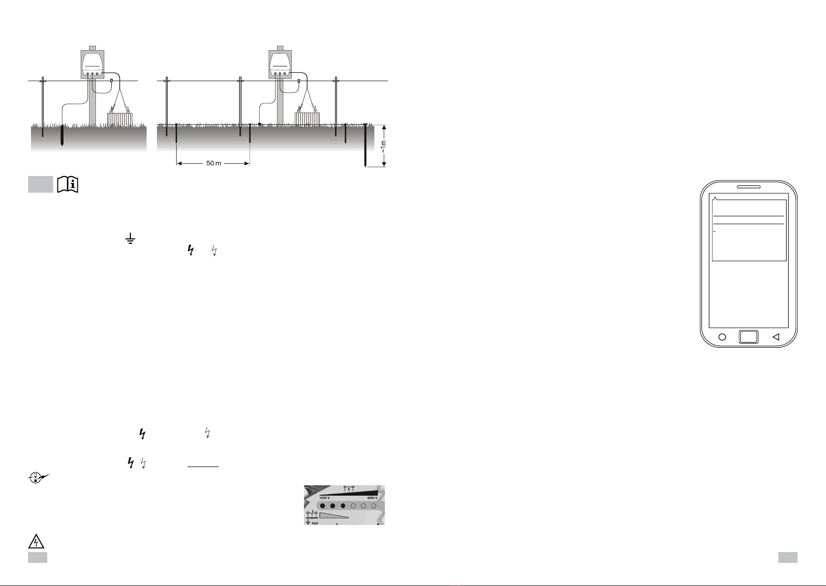
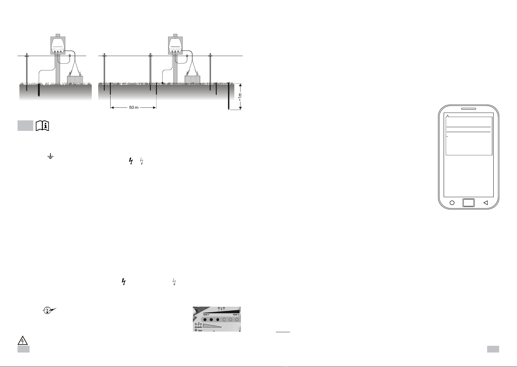
Montage et raccordement: L‘appareil peut être monté au choix sur un mur ou sur un piquet solide.
Le piquet de mise à la terre doit être enfoncé le plus profond possible dans le sol à un endroit humide et relié à la borne
de terre ( ) de l‘électrificateur par un fil non corrosif.
Raccorder le câble de raccordement de la clôture ( ou ) - fig. 3.
ll n’est protégé de l’humidité que lors par un montage correct. Ne pas exposé directement du soleil.
Ne pas mettre en marche l‘appareil couché sur le sol.
Mise en service et contrôle (fig. 2) : Raccorder l‘accumulateur 12V, veiller à ce que les bornes polaires soient propres
et à la bonne polarité ( rouge + / noir - ). Utilisez seulement 12V batteries-Gel-Plomb (rechargeables), les batteries-
Gel-Plomb doivent être placées dans un espace ventilé.
Cet appareil bénéfice du système d’économie d’énérgie: l‘appareil est équipé du circuit d’économie d’énergie
électrique, la consommation de courant est automatiquement ajustée à l’état de la clôture. Si la clôture est conven-
ablement isolée et entretenue, la consommation de courant reste faible. Une bonne isolation assure aussi une bonne
performance de la clôture, puisque l’énergie économisée bénéficie à l’amplitude de l’impulsion suivante, garantissant
ainsi un meilleur effet de protection du bétail. Moindre consommation d’énergie signifie longévité accrue des accumu-
lateurs, moins de mises au rebuts et meilleure préservation de notre environnement (Contrôler régulièrement, les piles
et l‘etat de la clôture - tension de garde). Particulièrement adapté pour le fonctionnement solaire!
Presser l‘interrupteur (1) „accu-test“ (2) lumière constant vert = accu bon
no lumière et lumière clignotante vert = charger accu
Quelques secondes après on entend un tic-tac régulier, l’appareil est en marche.
Toutes les 6 lampes (3) clignotent au rythme des impulsions électriques (fig. 2).
Les 6 lampes (3) de contrôle de la clôture montrent la tension sur la ligne. La tension est indiquée par tranche de 1000V.
Si moins de 3 lampes (3000 Volts) s’allument il faut contrôler la ligne et l’appareil.
Causes possibles:
Avec clôture: Végétation trop abondante ou court-circuit de la clôture sur un piquet métallique.
Sans clôture: L‘appareil est défectueux. Au dessous de 3000V pour certains types d’animaux
la sécurité de gardiennage n’est pas garanti.
La clôture peut être branchée sur l’une des 2 bornes de l’appareil selon la puissance voulue :
(Z1) = puissance maximale (Z2) = puissance réduite (fig. 2)
Les 2 bornes peuvent être employées en même temps avec 2 clôtures différentes. Un court circuit sur la clôture reliée
à Z2 a peu d’influence sur Z1 mais un court-circuit sur Z1 entraîne une réduction de puissance sur Z2. Lorsque les 2
lignes de clôture (Z1 et Z2) fonctionnent ensemble, les lampes indicatrices montrent uniquement la puissance réduite.
ranger A70: Aussi, après la temporisation de 60 secondes, l‘électrificateur de clôture électrique, ne
délivrera pas plus de 5 joules!
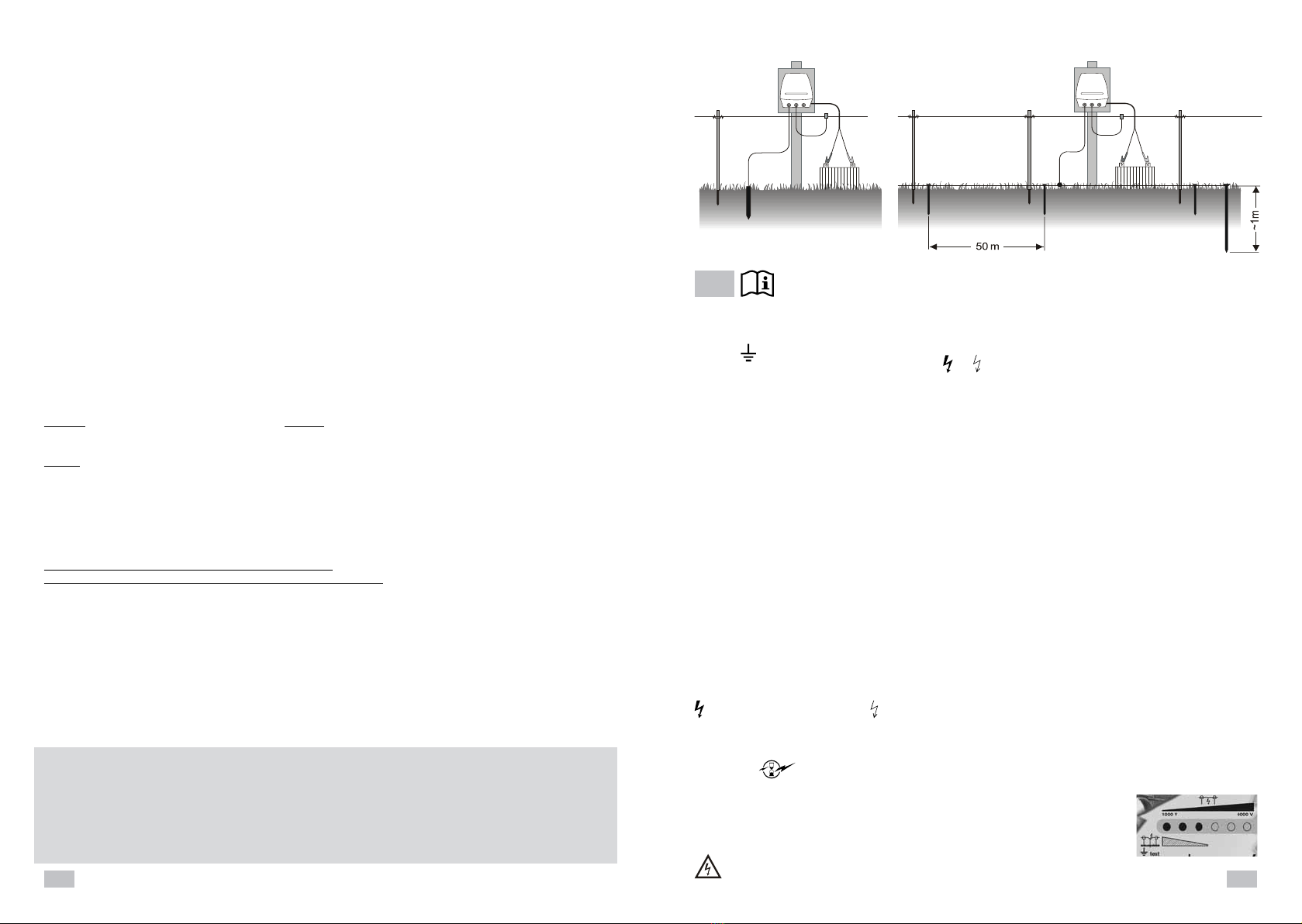
Vérification de la prise de terre (4): Provoquez un court-circuit à une distance d‘environ
50m de l‘électrificateur avec un piquet en acier fiché dans la terre en l‘appuyant contre la
clôture. Maintenant il ne devrait luire qui 1 lampe au maximum (terre mouillée) ou 2 lampes
au maximum (terre sèche) sinon (voir image) il faudrait ficher des piquets supplémentaires
Maintenance: Seulement du personnel qualifié est autorize d‘effectuer des répa-
ratures. Il ne faut utiliser que des pièces de rechange ordonnées par le producteur.
Fig. 3 Fig. 4
Montage et raccordement
Switch-on and off of the electric fencer:
Send a SMS to the additional device with following content: poweron
The given answer of the additional device will be: poweron ok
The additional device will switch-on the electric fencer.
Send a SMS to the additional device with following content: poweroff
The given answer of the additional device will be: poweroff ok
The additional device will switch off the electric fencer. The frequent tick of the fencer will stop and the fencing voltage
advice will not show any voltage. The additional device still operates.
Caution! If the fencer was switched off with the instruction “poweroff”, you have to switch on again with “poweron”.
Summertime and wintertime settings for the additional device:
Send a SMS to the additional device with following content: time zone 1
or time zone 2
Time zone 1 will regulate the additional device to winter time.
Timezone 2 will regulate the additional device to summer time.
The SMS won’t confirm from the module. You will receive with the next SMS on call the current regulated time.
Reset on factory setting:
Send a SMS to the additional device with following content: begin
The given answer of the additional device will be: begin ok
The additional device has been reset on factory setting.
Registering mobile phones:
IThe fencer accepts the communication with your mobile phone up to 4 more mobile phones. For this you need to
register your mobile phone as “Master”:
Send a SMS to the additional device with following content: admin YOUR MOBILE NUMBER
Beispiel: admin 00491718952860 (admin=Befehl; SPACE;
0049=country identification, 1718952860=YOUR mobile phone number)
Advise: To avoid further communication problems during the data transfer, please insert YOUR mobile number as its
deposited as “My number” in your own mobile phone.
Example: 00491718952860 or +491718952860 or 01718952860
The telephone numbers disagree with the country identification.
The given answer of the additional device will be admin IHRE Mobiltelefonnummer ok
Additional mobile phones can be registered by the master mobile phone:
Send a SMS to the additional device with following content: admin WEITERE Mobiltelefonnummer
Example: admin 0049171xxxxxxxxx(admin=Advise; Space;
0049= country identification; 171xxxxxxx= FURTHER mobile numbers
Additional mobile phones can be registered by the master mobile phone:
Send a SMS to the additional device with following content: admin FURTHER mobile numbers
Example: admin 0049171xxxxxxxxx(admin=Advise; Space;
0049= country identification; 171xxxxxxx= FURTHER mobile numbers
As before registered mobile phones just can check out when the additional device will be reset on factory setting.
Desired settings have to be reinstalled.
Any registered phone can serve the electric fencer as described. Alert messages will be sent to all registered phones.
All other confirmations will send to the phone which has activated the instruction.
Please look out for a stable mobile reception and a good cover with GPS-satellites
Depending on the mobile reception and the additional device it can be a time delay during SMS sending. Also can
accrue time delays because of the communication between different network operators.
The quantity of the satellites can vary because of bad meteorological conditions, fencer location under roofs or other
shields. The establishment can be impossible or incorrect. It can amount to incorrect establishments of the additional
device because of satellite drift.
Please ensure a good “view” from the electric fencer to the GPS-satellites to avoid time delay during the site location
or impreciseness during the establishment.

12 13
6. La mise sous tension et hors tension de l’électrificateur :
a. Envoyer un SMS au système GPS/SMS Control avec le contenu suivant : « poweron ».
La réponse de l’appareil sera : « ok power on ».
Le dispositif GPS/SMS Control se connectera à l’électrificateur.
b. Envoyer un SMS au système GPS/SMS Control avec le contenu suivant : « poweroff ».
La réponse de l’appareil sera : « ok poweroff »
Le dispositif GPS/SMS Control sera déconnecté de l’électrificateur. Les impulsions électriques de
l’électrificateur s’arrête et la tension affiche « 0 ». Le système GPS/SMS Control est toujours en fonction.
Attention ! Si l’électrificateur a été éteint avec l’instruction “poweroff”, vous devez renvoyer l’instruction
“poweron”.
7. Paramètres d’été et d’hiver pour le système GPS/SMS Control
a. Envoyez un SMS au système avec le contenu suivant : time zone 1 « fuseau horaire 1 » ou time zone
2« fuseau horaire 2 ».
Fuseau horaire 1 : va réguler le système GPS/SMS Control à l’heure d’hiver.
Fuseau horaire 2 : va réguler le système GPS/SMS Control à l’heure d’été.
Vous recevrez l’heure actualisée par SMS.
8. Réinitialiser le réglage usine :
Envoyez un SMS au système GPS/SMS Controlavec le contenu suivant : begin « commencer ».
La réponse de l’appareil sera : begin ok « commencer ok »
Le dispositif GPS/SMS Control a été réinitialisé sur le réglage usine.
9. Enregistrement de telephones mobiles :
L’électrificateur accepte la communication avec les telephones portables jusqu’à 4 téléphones mobiles.
Pour cela, vous devez enregistrer votre téléphone mobile comme “téléphone prioritaire”.
Envoyez un SMS au système GPS/SMS Control avec le contenu suivant : « admin (suivi de votre numéro
de mobile) ».
Exemple : admin 00336xxxxxxxx (admin= téléphone prioritaire ; espace ; 0033=identification du pays;
6xxxxxxxx=votre numéro de téléphone mobile).
Conseil : Pour éviter les problèmes de communication supplémentaires pendant le transfert des don-
nées, insérer votre numéro de téléphone portable comme « Mon numéro » à votre propre téléphone
mobile.
Exemple : 00336xxxxxxxx ou +336xxxxxxxx ou 06xxxxxxxx.
Les numéros de téléphone sont en désaccord avec l’identification du pays.
La réponse du dispositif GPS/SMS Control sera : « admin YOUR mobile number ok » soit votre nu-
méro de mobile est prioritaire.
D’autres telephones mobiles peuvent être enregistrés par votre telephone mobile “prioritaire” :
Envoyez un SMS au système GPS/SMS Control avec le contenu suivant : « admin FURTHER mobile
numbers » soit autres numéros de mobiles.
Exemple:admin00336xxxxxxxx(admin=conseiller; espace ; 0033=identification pays ; 6xxxxxxxx=autres
numéros de mobiles).
N’importe quel téléphone enregistré peut servir l’électrificateur comme décrit. Les messages d’alerte
sera envoyé à tous les téléphones enregistrés. Toutes les autres confirmations seront envoyés sur le
téléphone qui a activé l’instruction.
10. Déplacez-vous à l’extérieur pour une réception optimale et une bonne couverture de satellites GPS.
En fonction de la réception mobile du système GPS/SMS Control ; on peut constaté un temps de retard
lors de l’envoi de SMS. La quantité des satellites peuvent varier en raison des mauvaises conditions
météorologiques, l’emplacement de l’électrificateur qui peut être sous les toits, ou autres.
La connexion peut être impossible ou erronée. Assurez-vous une bonne « vue » de l’électrificateur aux
satellites GPS pour éviter les temps de retard lors de la localisation du site ou imprécision lors de la
connexion.
Mode d’emploi pour GPS et GSM Contrôle de sécurité:
Installation et raccordement:
Le système GPS Sécurité et Dispositif de contrôle SMS sont construits en pouvant fonctionner dans l’électrificateur.
Operation of the additional device GPS SECURITY and SMS CONTROL:
Connectez l’électrificateur à la batterie de 12V. Le module supplémentaire est disponible au bout de 2 minutes en-
viron.
Vérification de l’état en appelant le périphérique supplémentaire et le statut de conseiller pour obtenir des
informations d’état par SMS:
1. Appelez le dispositif supplémentaire à partir du téléphone. L’appel sera in-
terrompu au bout de 2 signaux d’appel. Vous recevrez un SMS du système
GPS/GSM Control avec les informations suivantes, que vous obtiendrez
avec chaque mise à jour d’état.
2. Vous pouvez entrer les coordonnées par vous-même dans google-maps et
interroger l’emplacement. Le lien peut être ouvert directement à partir de
votre téléphone mobile (smartphone) dans google-maps. L’emplacement de
l’électrificateur sera affiché
Loc : 51.51: coordonnées GPS de la position de l’électrificateur
3. Vitesse actuelle du GPS / SMS Control par rapport au sol
01/01/: Date et heure de la dernière position allouée.
F :4,32V… : tension actuelle de la batterie de secours du module sup
plémentaire.
M: 12,0V : tension actuelle de la source d’alimentation principale 12V.*
Signal: F or L : F signifie que le signal GPS est suffisant pour la localisation. L
signifie que le signal GPS est insuffisant pour la localisation.
Lmei: 012………..: numéro d’identification de périphérique.
Le voltage maximum affiché est de 12Volts (toutes les valeurs supérieurs
comme 13,6 Volts par exemple s‘affichent à 12 Volts). Cette valeur peut fluc-
tuer de plus ou moins 0,4 volts par rapport au voltage affiché.
4. Message d’alerte :
Vous obtiendrez des messages d’alerte de l’appareil, si les limites de tension sont atteintes ou si l’emplacement
de l’électrificateur a changé :
a. Signal : F basse tension : La tension de la source d’alimentation principale 12 V est tombé à 11,4 Volts ou
moins.
b. Signal : F batterie faible : la tension de la batterie de secours interne assure le fonctionnement du système
GPS pour quelques minutes de plus. Pendant ce temps, le GPS/SMS Control ne peut pas communiquer
avec vous, jusqu’à ce que l’électrificateur est de nouveau connecté à la source d’alimentation.
c. Signal : F propose : l’électrificateur a été déconnecté de sa source.
5. Fonctions : Localisation et Déplacement :
a. Envoyez un SMS au système avec le contenu suivant : move (mouvement ou déplacement).
La réponse du GPS/SMS Control sera : move OK (déplacement OK).
Le dispositif GPS/SMS Control permet de mémoriser l’emplacement. Si l’électrificateur est déplacé de
plus de 300m de l’emplacement alloué, le téléphone mobile connecté au système GPS/SMS control rece-
vra un SMS.
Le contenu du SMS sera : Signal : F déplacement.
b. Envoyez un SMS à l’autre appareil avec le contenu suivant : nomove
La réponse de l’appareil GPS/SMS Control sera : nomoveok
Le dispositif GPS/SMS Control mémorisera l’emplacement. La relocalisation ne sera pas signalée.
Conseil : avant d’enregistrer les nouvelles coordonnées de votre électrificateur, vous devez annuler
l’emplacement précédent en adressant un SMS « nomove ».
http://maps.google.com/
mapsßf=q&hl=en&q=loc
:
51.286368,8.857165
&sp
eed: 0.00 01/01/13 11:55
F:4,32V Signal:F Imei:
012896000578432
module supplémentaire:

14 15
Notizen / Notes / Note
Technische Daten - Technical data - Données techniques
ranger A70, Type 10852GPSD, 12 V DC, 150-880 mA / 6,6 Joule
TECHNISCHE ÄNDERUNGEN VORBEHALTEN ! SUBJECT TO TECHNICAL ALTERATIONS !
SOUS RÉSERVE DE CHANGEMENTS TECHNIQUES !
CEE: max. Zaunlänge
130 km
3
ranger A70 =
ranger A70 = 130 km
ranger A70 190 mA 190 mA 900 mA 400 mA 920 mA
~9500V ~14000V ~ 5400V ~ 9700V ~ 5400V
~9300V ~10500V ~ 2500V ~ 2900V ~ 1400V

16
This manual suits for next models
1
Table of contents
Languages:
Other Horizont Agrar Farm Equipment manuals

Horizont Agrar
Horizont Agrar RANGER N40 User manual

Horizont Agrar
Horizont Agrar farmer B2 Type 10441 User manual

Horizont Agrar
Horizont Agrar Scout N2 User manual

Horizont Agrar
Horizont Agrar horiSMART N70 User manual

Horizont Agrar
Horizont Agrar EQUISTOP M3 User manual

Horizont Agrar
Horizont Agrar ranger A3000 User manual
Popular Farm Equipment manuals by other brands

Janschitz
Janschitz Milky FJ 32 Operating instruction

waratah
waratah HTH622B SIII Operator's manual

sitrex
sitrex SR 320/8 H Use and Maintenance Spare Parts List

Geoline
Geoline GeoSystem 200 Operator's manual

LEMKEN
LEMKEN Solitair DT/400 operating instructions

BULK SEED SYSTEMS
BULK SEED SYSTEMS PRO-CHUTE 1 Setup