EFA Viking 3 User manual

Viking 3
(P5MVP3-AT)
AGP – PCI – ISA – I/O
Motherboard
User’s Manual
PART NUMBER: M556G00300 Rev 1.0JUNE 1998

Viking 3 Manual P5MVP3-AT Page 1
TABLE OF CONTENTS
1. SPECIFICATIONS 2
2. INSTALLATION GUIDE 3
2.1 Jumper Description 3
2.2 Processor Installation 4
2.3 DIMM Memory Installation 4
2.4 Mounting the Motherboard in the Case
and Connecting the Cables 4
3. JUMPER SETTINGS 6
3.1 CPU Voltage Settings 6
3.2 CPU Jumper Settings 6
3.3 SDRAM Clock Settings 7
3.4 Special Function Jumpers 7
3.5 Power Supply 8
3.6 Multifunction Connector 8
3.7 Memory Size 8
3.8 Jumper Layout Chart 9
4. AWARD BIOS SETUP 10
4.1 Entering Setup 10
4.2 Main Menu 10
4.3 Standard CMOS Setup 11
4.4 BIOS Features Setup 14
4.5 Chipset Features Setup 16
4.6 Power Management Setup 17
4.7 PnP/ PCI Configuration Setup 19
4.8 Load BIOS Defaults 20
4.9 Load Setup Defaults 20
4.10 Integrated Peripherals 21
4.11 Supervisor and User Password 22
4.12 IDE Hard Drive Auto Detection 23
4.13 Save and Exit Setup 23
4.14 Exit Without Saving 23
5. Troubleshooting 24

Viking 3 Manual P5MVP3-AT Page 2
SPECIFICATIONS
1. P5MVP3-AT Specifications
CPU CPU Support Intel Pentium /P54C/P54CS/P55C(MMX)
Cyrix 6x86/6x86L/6x86MX/M II
AMD K5/K6/K6-2
CPU Speed P54C:90/100/120/133/150/166/200MHz;
P55C:166/200/233/266/300MHz;
System Speed 60/66/75/83/100MHz
BIOS BIOS 1MB BIOS; PnP Compliant
BIOS ROM Flash Memory
CACHE Internal(L1) Write Back
External(L2) Pipe-line Burst Write Back SRAM(512K)
MEMORY DRAM Size From 4MB up to 768MB
DRAM Module DIMM x 3 of 168 Pin for Sync. DRAM(3.3V Non-
Buffer or 3.3V EDO)
Data Path 64 Bit Wide
On Board
I/O I/O Function Local Bus Enchanced Dual-Channel IDE
Bus Master PCI IDE / Mode 4 Support,
Ultra DMA-33 Mode Supports.
ECP/EPP Parallel Port
2 Serial Port
IR Function (Optional)
FDD Support
GREEN SYSTEM SMM Control, ACPI
VGA Control of DPMS
SLOT Expansion Slot 16 Bit ISA x 3
32 Bit PCI x 4 (4 Master Support)
AGP 1 AGP
Memory DIMM x 3
USB Two USB Ports (Optional Cable Must Be
Purchased)
Mouse PS/2 Mouse / Serial Mouse
Keyboard Keyboard CNN AT Keyboard (PS/2 Keyboard Optional)
Others Main Chipset VIA MVP3 Chipset
I/O Chipset SMC669
LM75/W8378D OPTIONAL
PCB Size 220mm x 230mm x 1.6mm, 4 layers
Viking 3 Manual P5MVP3-AT Page 3
1
1
2
5
6
1
3 1 3
INSTALLATION GUIDE
2. Installation Guide
Please follow these steps for proper installation of your high quality EFA motherboard
into your system:
A. Set the jumpers on the motherboard of the type of CPU you will be
installing.
B. Install the Central Processing Unit (CPU or processor).
C. Install the DIMM (Dual Inline Memory Modules).
D. Mount the motherboard in the case.
E. Connect all cables and wires to the motherboard.
F. Install the expansion cards.
Warning: The motherboard and other components contain many IC (Integrated
Circuit) chips. To protect them against damage from static electricity, please pay
attention to the following precautions whenever you are working with computer
components:
1. Unplug the power connector whenever you are working on the interior of the
computer.
2. Hold the motherboard, peripherals, and components by the edges and try not to
touch the IC chips, leads and circuitry.
3. If possible, use a grounded wrist strap when handling the components and place
them on a grounded anti-static pad or anti-static bag when they are pulled from the
computer.
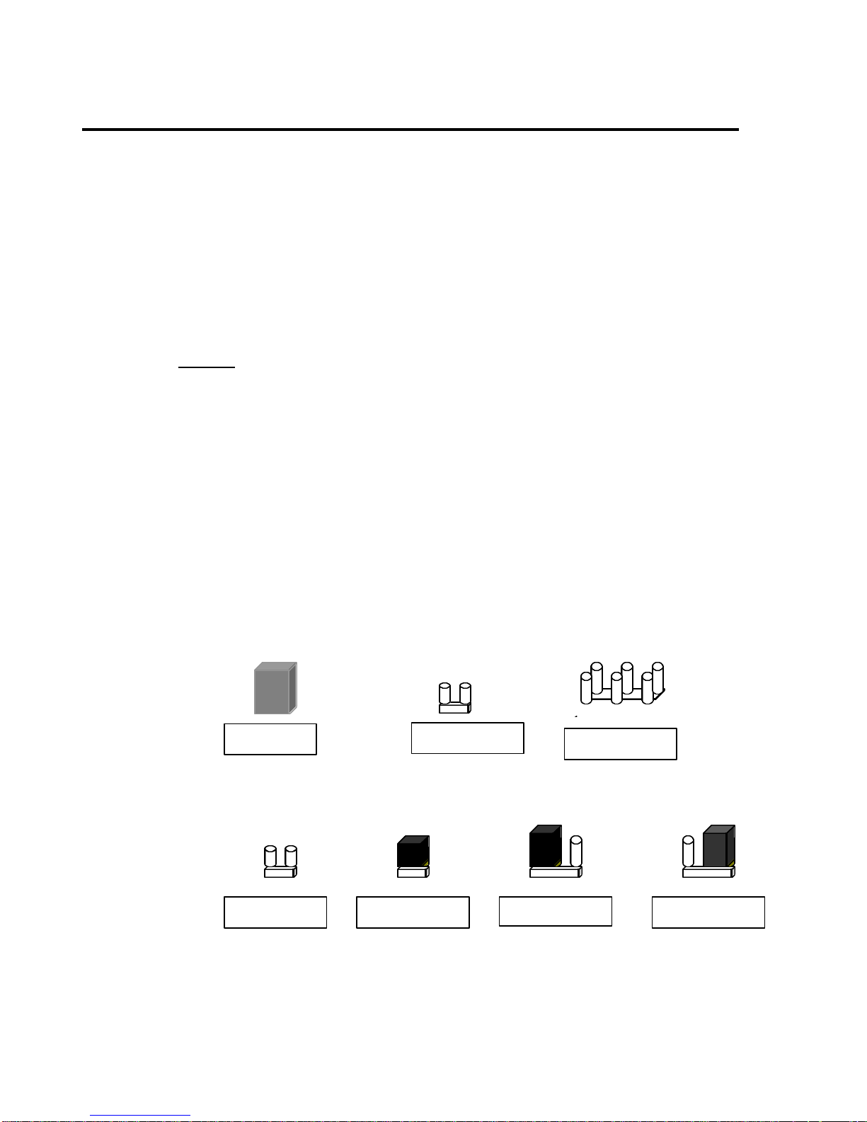
2.1 Jumper Description
Many hardware settings are made through the use of jumper caps connecting the
jumper pins (see the following figures). There are various jumper pins on the
motherboard such as two, three six and eight pin jumpers.
Please refer to the “Table of Jumper Settings“ in the manual. For jumper
examples, see below:
Note: Pin # 1 and the last pin for all the jumpers are silk-screened on the
motherboard.
You should now set the jumpers for the voltage, clock ratio, system clock and
CPU type. Please refer to the Jumper Settings section of this manual.
Pin 1-2 Closed
Pin 2–3 Closed
Jumper Cap 2-pin Jumper 6-pin Jumper
Open Jumper Closed Jumper

Viking 3 Manual P5MVP3-AT Page 4
INSTALLATION GUIDE
2.2 Processor Installation
Before putting the CPU into the CPU ZIF socket, lift up the locking bar on the
side of the socket, making sure that Pin 1 of the CPU (the corner with the notch)
is facing towards the notch on the CPU socket. Press the CPU firmly into the
socket making sure that it is firmly seated. Continue to push down on the CPU
while lowering the locking bar to lock the CPU in place.
It is always necessary to use a reliable CPU cooling fan with a heat sink.
Most fans will snap onto the ZIF socket.
2.3 DIMM Memory Installation
To install a DIMM module, simply line the notches of the module up with the
notches in the DIMM socket on the motherboard and push the module into the
socket and lock the plastic clips on the ends of the socket. DIMM memory can be
added one at a time.
2.4 Mounting the Motherboard in the Case and Connecting
the Cables
Mounting the Motherboard
Line up the keyboard connector on the motherboard with the keyboard hole on
the case. This should also help you in lining up the mounting holes on the
motherboard. Then use screws to mount the motherboard into the case.
Note: It is important that the motherboard is secure and does not touch the
bare metal of the case. This could cause the motherboard to short.
Power Cable (AT Power Supply)
Insert the P8 and P9 power cable connectors from the power supply into the
power socket on the motherboard. Make sure the ground (the black cable) on
both P8 and P9 are next to each other in the center when the cables are
connected to the motherboard. When inserting the power cables, tilt the P8 and
P9 connectors at 45-degree angle until it aligns with the notches on the power
socket on the motherboard. Then, tilt the cables back to a 90-degree angle and
push them down into the socket.
Power Cable (ATX Power Supply)
Line up the clip on the power cable’s connector with the notch on the ATX jack
on the motherboard and insert the cable in the jack.
P8 P9
Power Socket
Power Cable
Installation
Diagram
This manual suits for next models
1
Table of contents
Other EFA Motherboard manuals


