EFA Viking II P5VPX97-AT Operating and maintenance instructions

P5VPX97-AT Quick Installation Manual
V e r s i o n 1. 0
Viking II
• Check List
• Table of Contents
• Features
• Specifications
• Jumper Settings
• Installation Guide
• BIOS Features and Setup
P5VPX97-AT.p65 6/16/98, 3:31 PM1
P5VPX97-AT
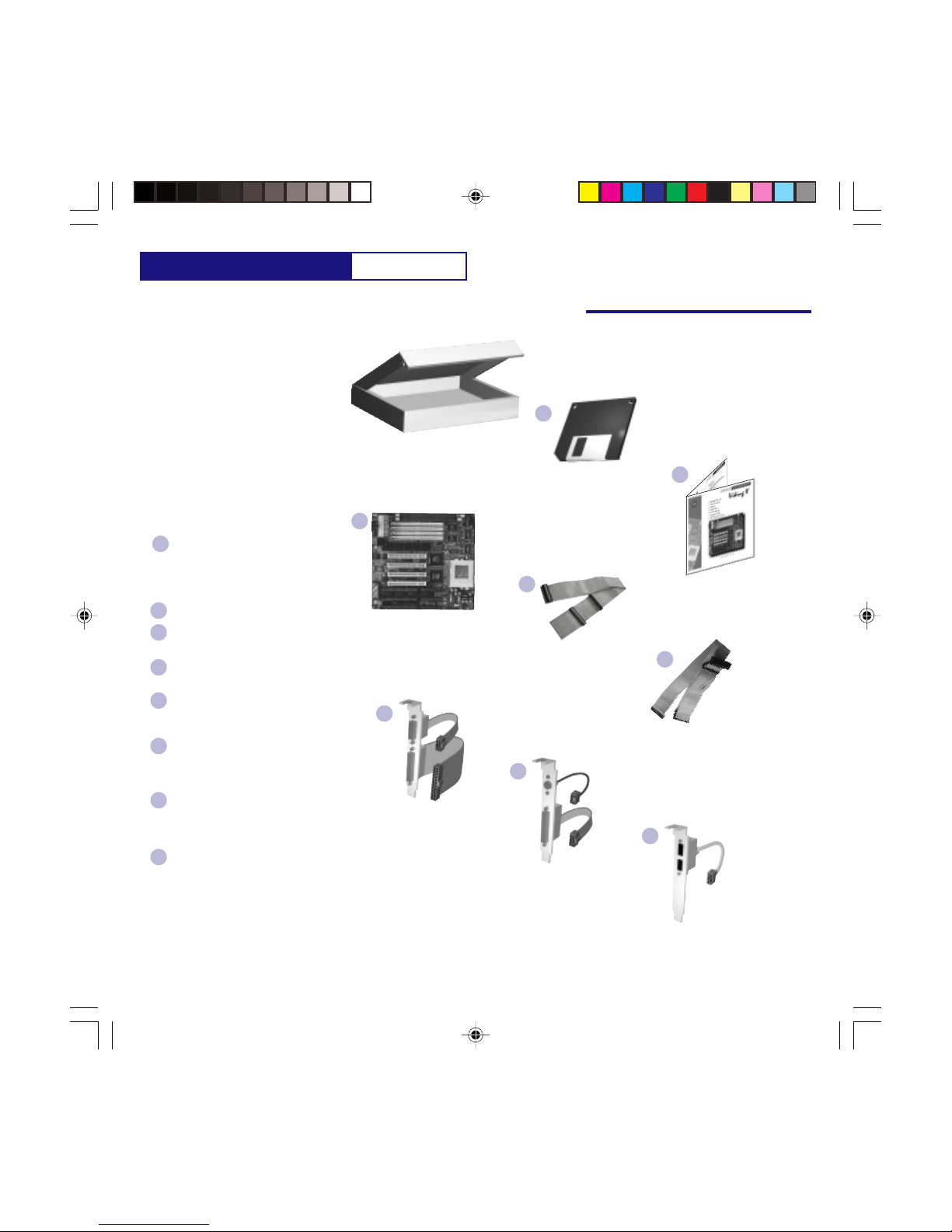
Hardware Check List
Check List
Packaging
Driver / Software
Diskettes
Installation Manual
BeforeYou Begin...
Our ISO9001/ ISO14000 facilities insure one
of the most accurate packaging in the industry.
For your protection, please check off the
contents listed below. If you are missing any
of the listed items, please contact your
distributor immediately.
Contents:
(1) Driver - Software - PDF Manual
Diskette
(All necessary drivers and software, are
included on the diskettes for your
convenience.
(1) Installation Manual (This one)
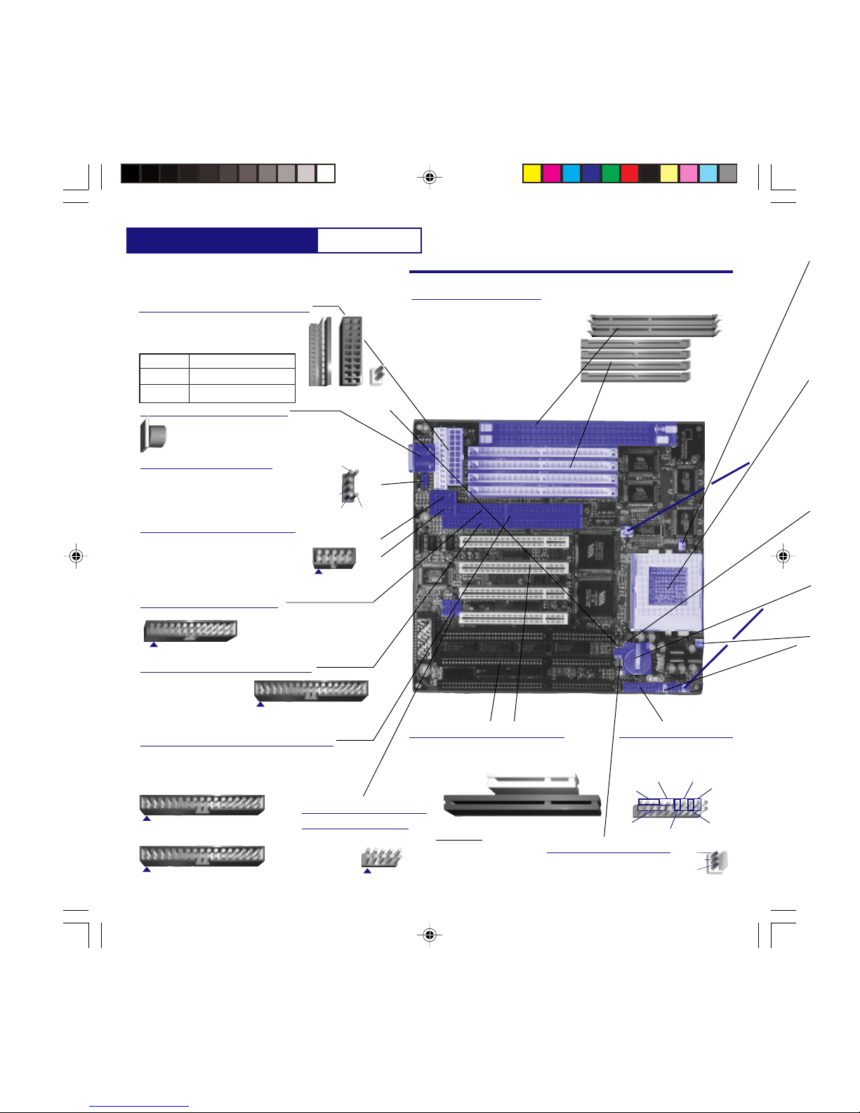
(1) Viking II (P5VPX97-AT) System
Board
(1) - 40-Pin IDE Ribbon Cable
(Internal connection to your IDE devices)
(1) - 34-Pin Floppy Ribbon Cable
(Internal connection to your floppy
disk drives)
(1) COM1-LPT1 Cable Assembly with
Bracket
(Provides COM1 and LPT1 connections
to the back of your computer chassis)
(1) PS/2 - COM2 Cable Assembly with
Bracket
(Provides PS/2 and COM2 connections
to the back of your computer chassis)
(1) USB Cable Assembly with Bracket
(Provides 2 USB connections to the back
of your computer chassis)
This item is optional and not included.
B
C
D
E
F
G
H
COM1 - LPT1
Cable Assembly
PS/2 - COM2
Cable Assembly
USB Cable Assembly
(Optional)
40-Pin IDE
Ribbon Cable
34-Pin Floppy
Ribbon Cable
A
D
B
E
F
G
H
Viking II System Board
C
A
P5VPX97-AT.p65 6/16/98, 3:31 PM2
P5VPX97-AT Table of Contents
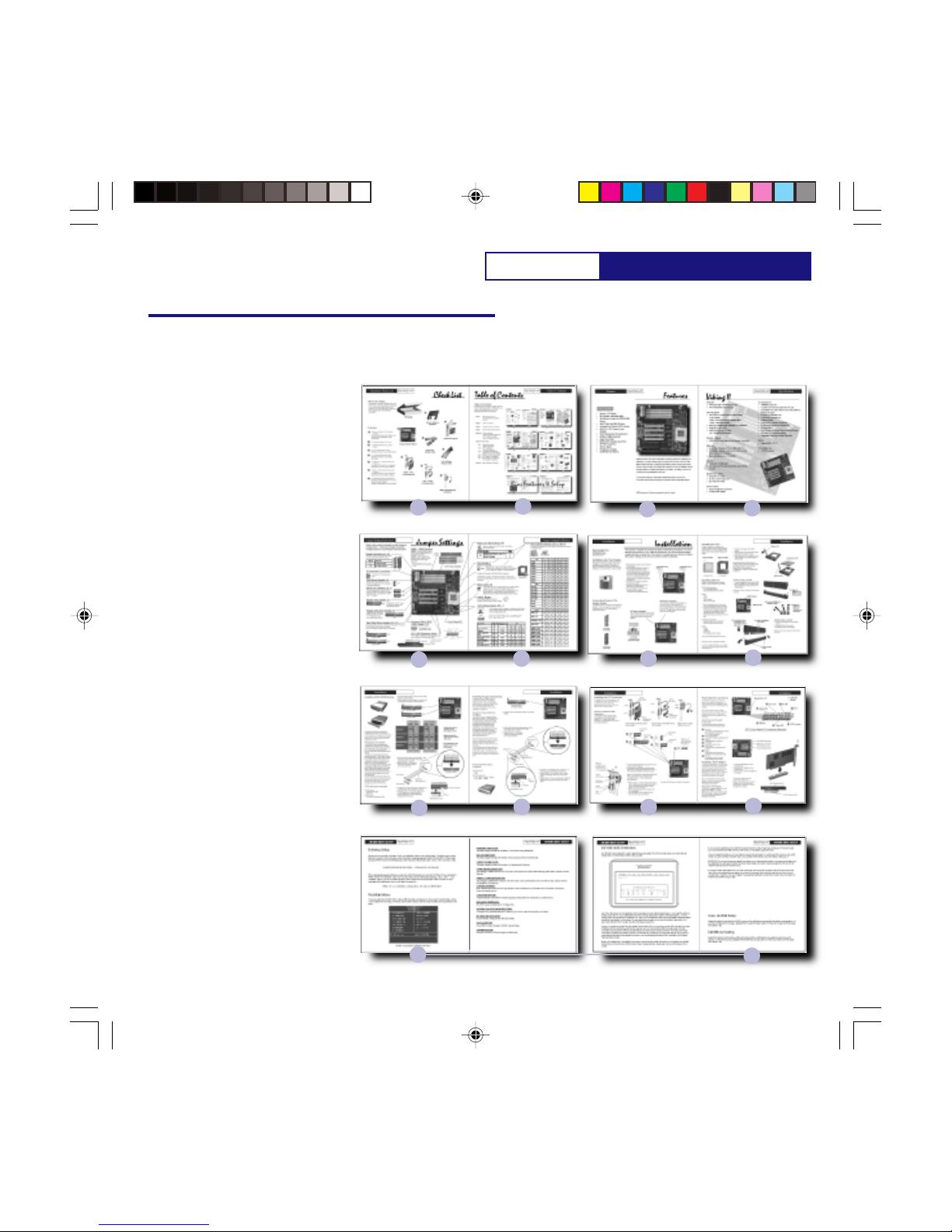
Table of Contents
5678
34
910 11 12
Table of Contents
Advanced users may skip to pages 5 and 6 for
jumper setting information. For beginners, we
recommend reading each section and
following each section step by step.
Page 1 Packing Information
All components included in
your kit.
Page 2 Table of Contents
Page 3 Features About Your Board
Page 4 System Board Specifications
Page 5-6 Jumper Settings
Connector Header Definitions
CPU, Voltage, Jumper Pinouts
Jumper Location Definition
Page 7-12 Installation
Pg.7 Chassis Mounting
Power Connection
Pg.8 CPU Installation
Memory Installation
Pg.9 ATAPI Device Installation
(Hard Disk Drive & CD-ROM)
Pg.10 Floppy Disk Drive Installation
Pg.11 I/O Connector Installation
Pg.12 Front Panel I/O Connection
VGA Adapter Installation
Page 13- BIOS Features and Setup
12
13
Bios Features & Setup
28
List
P5VPX97-AT.p65 6/16/98, 3:31 PM3
P5VPX97-AT
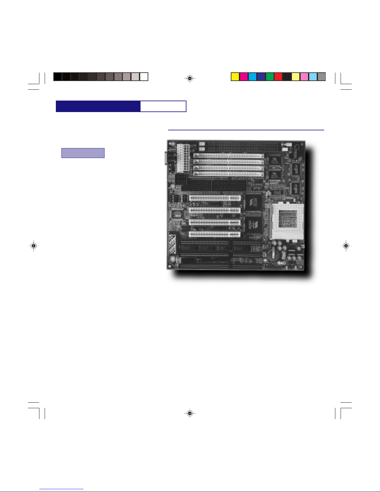
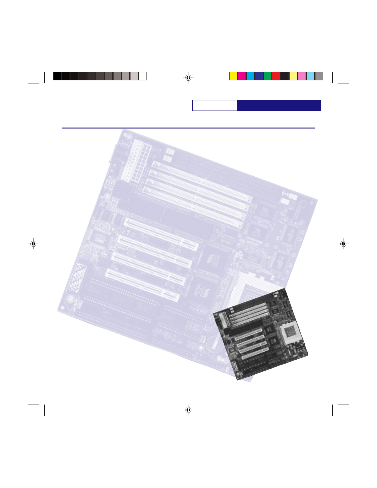
Features P5VPX97-AT
Features
FEATURES
EFA Corporation of America is dedicated to offer performance, reliability, and
flexibility in our system board designs. Designed and manufactured at our ISO
9001 compliant facilities, the Viking II system board offers a competitive socket-7
solution with the latest technologies. With support for the Ultra DMA 33 Protocol,
SDRAM DIMMs, and flexible BUS speeds up to 75MHz, the Viking II offers all the
amenities of a complete Socket-7 solution.
This quick installation guide provides detailed specifications and all the
information pertaining to the use and configuration of your new system board.
EFA Corporation of America reserves the right to change the specifications and/or
features of the Viking-II System Board. Please look for the updates at
www.efacorp.com.
• Socket-7 CPU Design
• BUS Speeds at 50/55/60/66/75MHz
• Fast Memory Access with SDRAM DIMM
Support.
• Fast I/O with Ultra DMA 33 Protocol
•Integrated Dual Channel EIDE Controller
•Support for Both AT or ATX Power
Supplies
•512K Pipe lined Burst Cache Standard
•SIMMs or DIMMs Supported
•Super I/O controller
• 65535 UART Compatible Serial Ports
• EPP/ECP Parallel Port
• USB via Header
• PS/2 Mouse via Header.
• 256MB Maximum Memory
P5VPX97-AT.p65 6/16/98, 3:31 PM4
P5VPX97-AT Specifications
Viking II
Chipset
• VIA Apollo 580 VPX/97 Core Logic
• VIA VT82C586B South Bridge
CPU Support
• Intel Pentium P54C/P54CS/P55CS/P55C
up to 233MHz
- P54C: 100/120/133/150/166/200 MHz
- P55C: 166/200/233 MHz
• IBM / Cyrix 6x86/6x86L/6x86MX up to PR233
• Cyrix MII up to PR300
• AMD K5/K6 up to 233 MHz
- K6: 166/200/233/266/300 MHz
System Speed
• 50/55/60/66/75 MHz System Bus Speeds
Supported
Memory
• (4) SIMMs 2 Banks of 72-pin (5V EDO/FP)
• (2) DIMMs 2 Banks of 168-pin for Sync or EDO
DRAM (3.3V 64-Bit Wide)
• Maximum Memory Up To 256MB
Cache
• Internal (L1) Write Back
• External (L2) Pipe-line Burst Write Back SRAM
(512K)
Expansion Slots
• (4) 32-Bit PCI Slots
• (3) 16-Bit ISA Slots
• (1) PCI / ISA Shared Slot
Form Factor
• Baby AT (220mm x 230mm)
• 4-Layer PCB Design
On Board I/O
• SMC669 Super I/O
• Local Bus Enhanced Dual-Channel IDE
• Bus Master PCI IDE / Mode 4 and Ultra DMA 33
Protocol Support
• 2 Serial I/O COMM Ports.
• 1 ECP/EPP Parallel Port
• FDD Controller
• SIR Function Header (Optional)
• 2 USB Ports (Optional USB Cable)
• AT Keyboard
• PS/2 Mouse (Optional Cable Included)
Power
• AT and ATX Power Connectors
• Integrated Switching Voltage Regulator
BIOS
• Award BIOS 4.51PG
Compliancies
• PC97 Compliant
• DOC Compliant
•CD
P5VPX97-AT
P5VPX97-AT.p65 6/16/98, 3:31 PM5
P5VPX97-AT
Jumper Setting Reference
REPMUJNOITCNUF
1JrotcennoCrewoPTA
2JrotcennoCrewoPXTA
CPU Fan Header
Power Connector J1, J2, J15
Serial Port Headers J6, J7
[J6]
[J7]
Communication ports 1 [J6] and 2 [J7]
(COM1, COM2). Used for mice, external
modems, and other input / output devices.
16550 UART compatible.
Floppy Disk Drive Header J9
Dual channel IDE controller. Support for Ultra DMA 33 Protocol.
Primary has priority over the secondary.
Up to 2 devices per channel may be connected.
AT Keyboard Connector
SIMM - DIMM Sockets
[DIMM 1]
[DIMM 2]
[SIMM 4]
[SIMM 3]
[SIMM 2]
[SIMM 1]
SIMMS - must be installed in pairs.
72-pin, 70ns or faster, EDO or F.P.
RAM types supported.
DIMMS - may be installed one
piece at a time. 168-pin 3.3Volt,
unbuffered SDRAM or EDO RAM types
supported.
*DIMMs and SIMMs may not be used
simultaneously due to the difference in
voltage.
PS2 Mouse Header J5
Parallel Port Header J8
PS2 or BUS mouse header.
Connect the PS2 mouse
bracket. The connector is
keyed for alignment.
Connect an AT type keyboard here.
Both an AT and ATX type of power supply
may be used with this system board. If
using an ATX power supply, you must
trigger the power on/off via shorting J15
[J1] [J2]
Parallel port 1. (LPT1). Used
to connect to printers and
other parallel devices.
Floppy disk drive controller.
Used to connect 3-1/2” and
5-1/4” floppy drives and
some backup tape devices.
Hard Disk Drive Header J10, J11
[J8]
[J9]
[J10]
[J11]
Secondary IDE
PrimaryIDE
PCI / ISA Expansion Slots
4PCI / 3ISA / 1 Shared PCI-ISA expansion slots
are available for your expansion cards.
PCI 32-bit
ISA 8-bit / 16-bit
**For best performance,
use PCI cards when
possible.
Front Panel I/O J17
Jumper Settings
Refer to this section for details on the hardware
configuration. All jumper settings should be
configured prior to installing the system board.
Connection to your chassis’
front panel display and
controls.
2
33
34
2
25
26
2
9
10
Pin-1
Pin-1
Pin-1
2
39
40
Pin-1
2
39
40
Pin-1
1- MS Data
2- NC
3- GRND
4- NC
5- MS CK
6- NC
[J5]
5
1
3
Universal Serial BUS
(USB) Header J13
[J13]
USB header
for the
optional USB
Cable. 9
10
2
Pin-1
1- Ground
3- USBDAT0-
5- USBDAT0+
7- Ground
9- Ground
2- Ground
4- Ground
6- USBDAT0+
8- USBDAT0-
10-Ground
USB Pinout:
++
+++++
+
-
----
--
Power LED
Key Lock
Turbo LED
Speaker HDD Activity
Reset
Ext SMI
CPU Fan Header J16
Connection for your 3-pin CPU
cooling fan.
Grnd
(+) 12V
Grnd
[J15]
ATX on/off
4
P5VPX97-AT.p65 6/16/98, 3:31 PM6

P5VPX97-AT Jumper Setting Reference
letnI1PJ2PJ3PJ8PJ9PJ01PJ
zHM573-23-23-2FFOFFOFFO
zHM092-13-23-2FFOFFOFFO
zHM0212-13-23-2NOFFOFFO
zHM0512-13-23-2NONOFFO
zHM0013-22-13-2FFOFFOFFO
zHM3313-22-13-2NOFFOFFO
zHM6613-22-13-2NONOFFO
zHM0023-22-13-2FFONOFFO
zHM3323-22-13-2FFOFFOFFO
XIRYC1PJ2PJ3PJ8PJ9PJ01PJ
+331P-68x6 3-23-22-1NOFFOFFO
+051P-68x6 2-13-23-2NOFFOFFO
+661P-L68x6/68x6 3-22-13-2NOFFOFFO
+002P-L68x6 2-13-22-1NOFFOFFO
661RP-XM68x6 x5.2SUBzHM06 2-13-23-2NONOFFO
661RP-XM68x6 x0.2SUBzHM66 3-22-13-2NOFFOFFO
002RP-XM68x6 x5.2SUBzHM66 3-22-13-2NONOFFO
002RP-XM68x6 x0.2SUBzHM57 2-13-22-1NOFFOFFO
332RP-XM68x6 x5.2SUBzHM57 2-13-22-1NONOFFO
003RPIIM68x6 x0.3SUBzHM57 2-13-22-1FFONOFFO
DMA1PJ2PJ3PJ8PJ9PJ01PJ
09RP-5K2-13-23-2FFOFFOFFO
001RP-5K3-22-13-2FFOFFOFFO
021RP-5K2-13-23-2FFOFFOFFO
331RP-5K3-22-13-2FFOFFOFFO
051RP-5K2-13-23-2NONOFFO
661RP-5K3-22-13-2NONOFFO
661-6K3-22-13-2NONOFFO
002-6K3-22-13-2FFONOFFO
332-6K3-22-13-2FFOFFOFFO
662-6K3-22-13-2NOFFONO
003-6K3-22-13-2NONONO
EPYTUPC5PJ6PJeroCegatloV7PJ
ABCDE
)zHM003,662(6KDMA3-23-2tloV2.2FFONOFFOFFOFFO
devreseR**tloV5.2NOFFONOFFOFFO
)zHM662(XMxiryC3-23-2tloV7.2NONONOFFOFFO
xiryC/XMMmuitneP 68x6 3-23-2tloV8.2FFOFFOFFONOFFO
)zHM002-661(6KDMA ,68x6xiryC )zHM003(IIMxiryC 3-23-2tloV9.2NOFFOFFONOFFO
)zHM332(6KDMA3-23-2tloV2.3FFOFFONONOFFO
muitnePletnI2-12-1tloV3.3NOFFONONOFFO
5KDMA/68x6xiryC2-12-1tloV5.3NONONONOFFO
Pipe-line Burst Mode JP4
repmuJnoitcnuFgnitteS
4PJ sUPCxiryCrofnoedoMtsruBdenilepiP
)tluafeD(sUPCrehtO
2-1
3-2
CPU Jumper Setting JP1-3, JP8-10
CPU Voltage Select JP5 - 7
Use this mode for Cyrix CPUs only. For all other
CPUs set to default Find the CPU manufacturer then configure the jumpers according
to the tables below.
CPUs require specific voltages according to the CPU type.
When possible, please refer to the CPU manufacturer for
correct voltage requirements
***There are 2 AMD K6 233MHz CPUs. One requires 2.2Volts, and
the other 3.2Volts. Please verify your AMD K6 233MHz CPU’s
voltage requirements before configuring your voltage settings.
1
33
1
[JP5] [JP6]
E
ABCD
[JP7]
1
2
3
[JP1] [JP2][JP3]
1
2
3
[JP8] [JP9] [JP10]
CPU Socket 7
CPU types supported
Intel -Pentium /54C /54CS /P55C up to 233MHz
IBM / Cyrix - 6x86 /6x86L /6x86MX up to PR233 / MII 300MHz
AMD - K5 / K6 166MHz / 200MHz / 233MHz /
266MHz / 300MHz
Variable BUS speeds of 50/55/60/66/75MHz Supported
Installing the processor: Swing the locking arm on the socket
up, look for the indentation on one of the corners of the CPU.
Insert straight down then lock the arm back to its place.
CPU Socket 7
BIOS Clear J14
Set to pins 1-2 for normal operation.
In the event that your computer does not boot after a BIOS
adjustment, you may clear the BIOS settings back to factory
defaults. To clear your CMOS, power down, short pins 2-3 for
2-5 seconds, then replace the jumper back to pins 1-2.
Reboot and factory default BIOS settings will be invoked.
CMOS Battery
[J14]
3 Volt Lithium Battery [CR2032]
Replace if BIOS does not keep
settings.
Voltage
Clock Ratio
BUS Speed
Example:
[JP8] [JP9] [JP10]
ON OFF OFF
1
3
2
Panel I/O J17
P5VPX97-AT.p65 6/16/98, 3:31 PM7
P5VPX97-AT
Installation
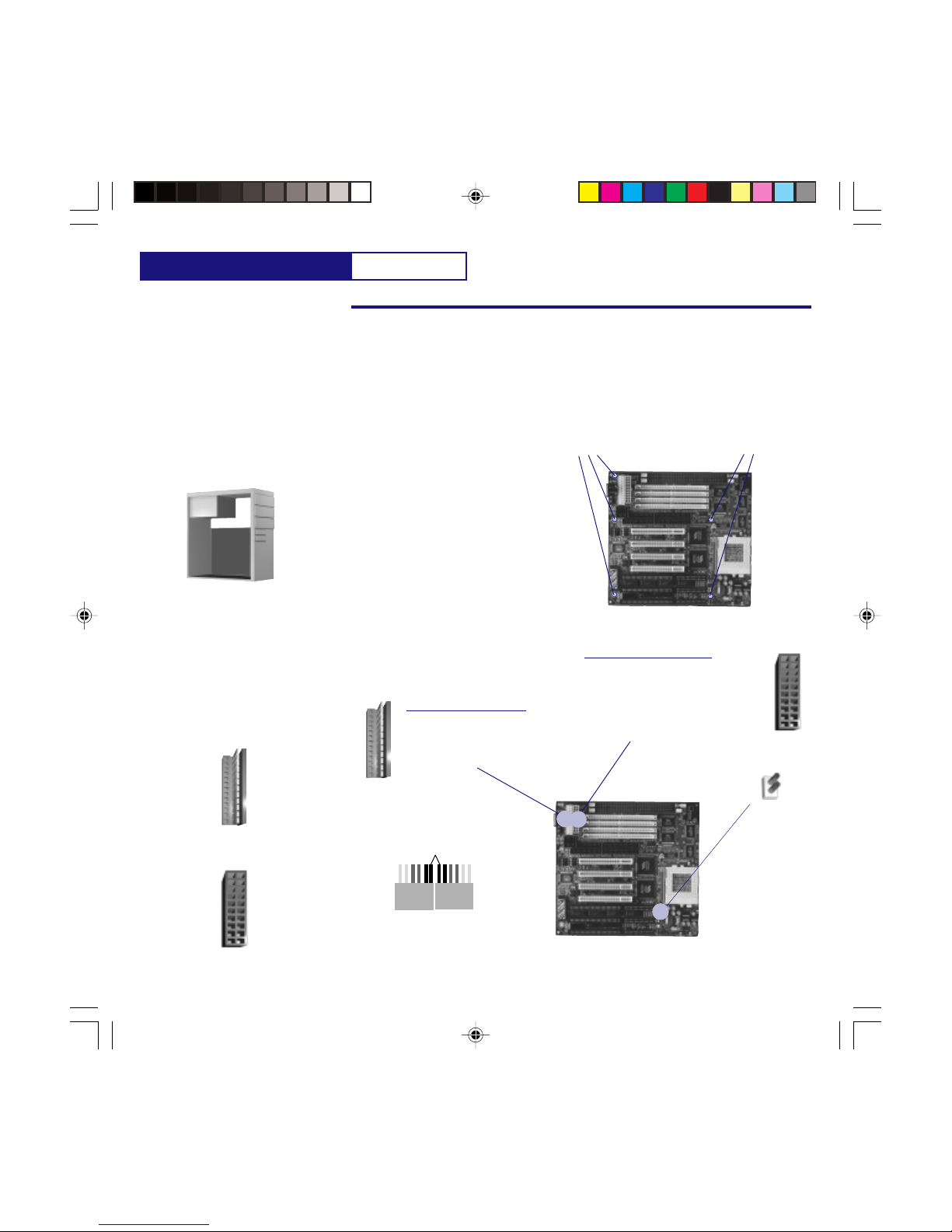
Installation intoThe Chassis
Installation
Every chassis will have it’s own instructions for
installation. Whenever possible, refer to the
manufacturer’s instructions. Provided is a
generic installation procedure for the Viking II
installation. You will need an AT type of
chassis.
1. Plug the power supply of your chassis
to the wall outlet.
2. Anchor the grounding wrist strap to a
non-painted metal surface of the
chassis and wear the wrist strap at all
times while handling the system board.
If you don’t have a grounding strap,
touch a non-painted surface of the
chassis each time before handling the
system board.
3. Locate the mounting hole positions
of the system board.
4. Align the mounting position of your
chassis to the system board.
5. Mount the system board on to the
chassis using the chassis
manufacturer’s supplied hardware.
Chassis Mounting
Positions
Chassis Mounting
Positions
Connecting Power toThe
System Board
AT Power
Connector
ATX Power
Connector
Two different power connectors are supplied
for flexibility. You may use either one but not
both at the same time. An AT power supply is
preferred if possible. An AT power connector comes in
pairs. When connecting to the
system board make sure the black
wires are kept together.
AT Power Connector J1
ATX Power Connector J2
This section will guide you though the basic installation procedures. For
more detailed instructions on your specific peripherals, use the installation
guides supplied by the manufacturer. If you haven’t already done so, please
configure the jumper settings in the previous section before installation.
RecommendedTools
Phillips Screw Driver
Grounding Wrist Strap
Needle Nose Pliers
Keep the black
wires together
AT Power
Connector from
the power supply.
An ATX power connector is keyed on the
connector and its header so they mate only
one possible way. When using an ATX
power supply however, J15 must be
connected to a momentary power switch to
trigger the on/off function of an ATX power
supply.
AT Power
Connector
ATX Power
Connector
[J15]
ATX on/off
Connect to your
power switch in
the front of your
ATX momentary
power switch.
J15
J1 J2
P5VPX97-AT.p65 6/16/98, 3:31 PM8
P5VPX97-AT Installation
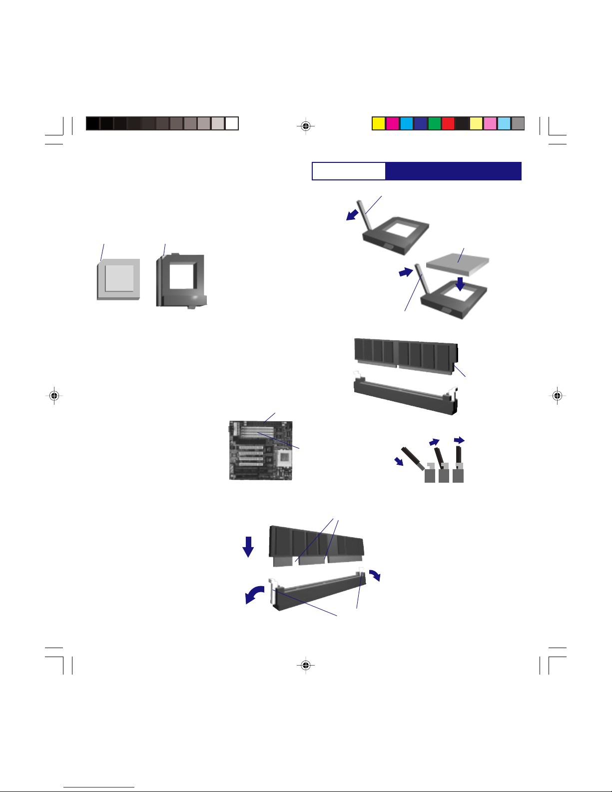
Installing the CPU
Installing Memory
1. Open the locking arm of the CPU
socket.
2. Align the CPU to the socket then insert
pressing firmly into the socket.
3. Make sure the CPU is seated firmly into
the socket then close the locking arm
of the socket.
Most Pentium Class CPUs require a
cooling fan and heat sink for appropriate
operating temperature requirements.
Please refer to the cooling fan
manufacturer for details on installing the
cooling fan.
CPU Socket 7
Alignment Edge
Alignment Edge
Pentium CPU
(2) Align the CPU
(3) Close Arm
Please make sure to configure your
system board for the correct BUS speed,
CPU frequency, and CPU voltage settings.
Refer to the “Jumper Setting” Section for
details.
SIMMs: Single Inline Memory Modules
DIMMs: Dual Inline Memory Modules
SIMM types supported:
F.P. (Fast Page) DRAM
EDO (Extended Data Out) DRAM
Specs:
5 Volt
72-Pin
70ns or faster
Parity or non parity
When installing SIMMs:
** Must be installed in pairs. Each pair
must be of equal size, speed, and type.
** The identical SIMM types must occupy
SIMM sockets 1&2 and/or 3&4 but not
in any other combinations. SIMM 1&2
and 3&4 make up a memory bank.
Each bank must have the same
memory type.
DIMM types supported:
EDO (Extended Data Out) DRAM
SDRAM (Synchronous) DRAM
Specs:
3.3Volt
168-Pin
Unbuffered
ECC Supported Via Chipset
**May be installed one DIMM at a time.
Maximum memory capacity is 256MB.
Due to the voltage difference, we strongly
recommend not to use SIMMs and DIMMs
at the same time.
(1) Open Arm
SIMM INSTALLATION
1. Locate the alignment notch of the SIMM
2. Insert the SIMMs at a 45 degree angle
3. Snap the SIMMs into place as shown in
the illustration.
Maximum memory capacity of the Viking II
is 256MB.
DIMM INSTALLATION
1. Open the locking levers on the DIMM
socket.
2. Align the DIMM to the socket.
3. Press firmly down on the DIMM
Maximum memory capacity of the Viking II
is 256MB.
(1) Open locking
arms
(2) Align the DIMM to
the socket.
(3) Press firmly down
90 degrees on to
the socket until the
arms lock.
SIMM Sockets
DIMM Sockets
(1) Align the
SIMMs to the
Socket. (Look
for the notch)
(2) Insert the SIMMs at a
45 degree angle. (3) Snap the
SIMMs into
place as
shown in this
illustration.
int l
e
P5VPX97-AT.p65 6/16/98, 3:31 PM9

P5VPX97-AT
Installation
Installing ATAPI EIDE Devices. 1. Note the location of the Primary and Secondary
EIDE Controller Headers.
2. Study the device priority diagram below then set
your devices as a slave or a master device.
About Dual Channel EIDE
The P5VPX97 has an integrated dual
channel EIDE controller; a primary and a
secondary. Each channel may support up
to 2 ATAPI EIDE devices, Hard Disk
Drives, CD-ROMs or other standard
ATAPI devices.
The primary channel has priority to the
secondary channel. Within each channel,
the two different devices are distinguished
by a master and slave relationship. The
master device has priority over the slave
device. E.G. If you are installing two
devices on a single channel, the master
will be assigned a higher drive letter than
the slave. (Refer to Fig A. on the right)
When installing a CD-ROM(s) with hard
disk drive(s), the hard disk drives will
have priority drive letter assignments over
the CD-ROM drives.
When installing more than one device per
channel, you must set one as a master
and the other as its slave device. These
device settings are usually determined by
a jumper that is on the ATAPI device.
ATAPI drive types supported:
MODE Support:
Ultra DMA 33 Mode
Mode 4 - 0
Maximum Size
9.0 GB EIDE via System BIOS
3. Orient the 40-pin ribbon cable as shown. Note
the location of the red stripe on the cable
indicating its pin-1 location.
4. Align up the pin-1 of the ribbon
cable to the controller header’s
pin-1 then insert firmly.
Master Device
Slave Device
To Controller
Header
Red Stripe
(Indicating Pin-1)
ControllerHeader
Pin-1
40-Pin Ribbon Cable
Rear of Hard Disk Drive
PowerConnector
40-Pin Ribbon Cable
Pin-1
5. Locate pin-1 on the ATAPI device. (Note: pin-1 is
usually located next to the power connector)
6. Align pin-1 of the ribbon cable to the
ATAPI header’s pin-1 then insert firmly.
7. Repeat steps 5-6 if you are installing any
additional ATAPI devices.
The following instructions are generic
installation procedures for installing an
ATAPI EIDE device. If you have
instructions that came with your ATAPI
devices, please refer to it for more detailed
instructions regarding your drive.
C: E:
HDD CD
Scenerio 3
Master Slave
F: D:
CD HDD
Secondary EIDE
Primary EIDE
C:
C: D:
HDD
HDD HDD
Scenario 1
Scenerio 2
Primary Channel has
priority over the
Secondary Channel
Master has priority
over the slave devices
(HDD only)
Hard disk Drives have
priority over the CD-
ROM devices
Master Slave
E: F:
HDD HDD
D:
HDD
Fig A. Device Priority Diagram
[J10]
[J11]
Secondary IDE
PrimaryIDE
2
39
40
Pin-1
2
39
40
Pin-1
J10
J11
P5VPX97-AT.p65 6/16/98, 3:31 PM10

P5VPX97-AT Installation
Installing Floppy Disk Drive(s).
The following instructions are generic
installation procedures for installing a
floppy disk drive. If you are installing a
tape backup drive that uses the floppy
disk drive controller, please refer to the
respective manufacturer’s instructions
regarding it’s installation.
About The Floppy Disk Drive
Controller
The P5VPX97 has an integrated floppy
disk drive controller. It may support up to
two floppy disk drive devices of various
sizes and densities. Similar to the EIDE
controller the two floppy devices are
distinguished by a master and slave
relationship. The master device has
priority over the slave device. E.G. If you
are installing two devices on a single
channel, the master will be assigned the
reserved floppy disk drive letter “A:\”
and the slave device “B:\”.
Unlike the EIDE controllers where master
and slave relationship is determined via a
jumper, floppy disk drive’s priority is
determined by the location of the drive on
the cable.
When installing only one floppy disk drive,
you must connect it to the master position
on the ribbon cable. (Trying to set your
single drive as a slave only will prevent
the computer from booting from the floppy
disk drive.)
Floppy Disk Drive Types
Supported:
Sizes Supported:
3-1/2”
5-1/4”
Densities Supported:
3-1/2”: 740K / 1.44MB / 2.88MB
5-1/4”: 560K / 1.22MB
2. Orient the 36-pin ribbon cable as shown. Note
the location of the red stripe on the cable
indicating its pin-1 location.
4. Align pin-1 of the ribbon
cable to the controller header’s
pin-1 then insert firmly.
Master Device
Slave Device
To Controller
Header
Red Stripe
(Indicating Pin-1)
ControllerHeader
Pin-1
36-Pin Ribbon Cable
5. Locate pin-1 on the floppy drive. (Note: pin-1 is
located usually next to the power connector.
6. Align up the pin-1 of the ribbon cable’s master
position to the floppy drive’s pin-1 then insert
firmly.
7. Repeat steps 5-6 if you are installing an
additional floppy drive on the slave position of
the ribbon cable.
Rear of Floppy Disk Drive
Power
Connector
36-Pin Ribbon Cable
Pin-1
1. Note the location of the floppy disk drive
controller header.
J9
[J9]
2
33
34
Pin-1
Floppy Disk Drive
ControllerHeader
P5VPX97-AT.p65 6/16/98, 3:31 PM11
P5VPX97-AT
Installation
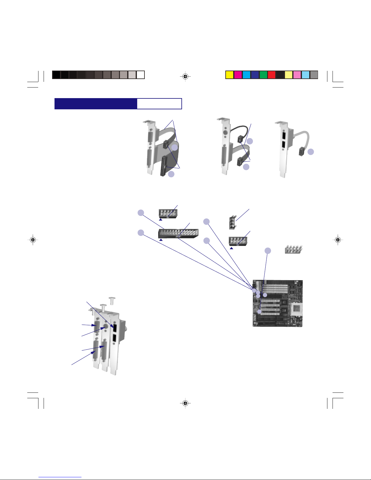
Installing the I/O Connectors
The P5VPX97 is an AT form factor. In an
AT design, you must connect the serial,
parallel, PS/2, and or USB cable
assemblies then attach them to the rear
panel of your AT style chassis.
LPT 1
Serial (COM1) and Parallel (LPT1)
cableassembly. Serial (COM2) and PS/2 (BUS Mouse)
cableassembly. USB port cable assembly
(Optional Accessory)
COM1
COM2
PS/2
About The Supplied Cable
Assemblies
The P5VPX97 comes with two cable
assemblies. (1) Serial-Parallel and (1)
Serial-PS/2. The third, USB cable
assembly, is an optional item and may be
purchased separately.
1. Mount the cable assemblies using a screw driver
to the rear of the chassis.
2. Using the above descriptions about the cable
assemblies, plug the appropriate connectors to
their respective headers on the system board.
(NOTE: The connectors are keyed to prevent
you from connecting them wrong. Always note
the orientation of pin-1. It can be located as
described below :
** Ribbon cables - The serial and parallel cables
have a red stripe on the cable to mark Pin-1.
Their connectors are also keyed to fit the
header in only one direction.
** PS/2 Cable are keyed on the connector for
Pin-1 orientation.
** The USB need not be keyed since it will
function either way you connect it.
(Pin-1)
Red Stripe
Keyed
connectors for
orientation.
(Pin-1)
Red Stripe
Keyed
connectors for
orientation.
Location of The Headers and Their Orientation
USB
[J13]
A
B
C
D
E
F
CB
A
D
A
B
C
D
E
USB1
USB2
Pin-1
LPT 1
[J8]
Pin-1
COM1
[J6]
COM2
[J7]
Pin-1
PS/2
[J5] Orientation
Notch.
Orientation
Notch.
Orientation
Notch.
Orientation
Notch.
USB does not
have a pin-1 and
does not have to
be oriented.
COM1
(Serial Mouse)
LPT1
(Printer)
COM2
(Ext. modem etc.)
PS/2 Mouse
(BUS Mouse)
USB A,B
(USB devices e.g.
Keyboard, mouse,
scanner, camera, etc.
Hot pluggable)
Refer to the Jumper Setting Section for detailed pinouts.
P5VPX97-AT.p65 6/16/98, 3:31 PM12
P5VPX97-AT Installation
[J17] Front Panel I/O Connector Definition
Front Panel I/O Connectors
The P5VPX97 connectors to the front
panel I/O are located on jumper block J17.
Follow the instructions carefully for proper
connections to your front panel display
and controls.
Note: Some chassis may not supply
connections to the Turbo LED, Ext. SMI,
or the Key Lock functions. These are not
essential to the normal operation and may
be left out.
About The Front Panel I/O
Connectors.
The P5VPX97 provides front panel I/O
connections for the following functions:
Jumper Block J17 +Cathode
+-
Power LED
Key Lock
Turbo LED
Speaker
Ext SMI
+
++ ++++
-- --- --
A
CD
B
G
HDD Activity
E
-Anode
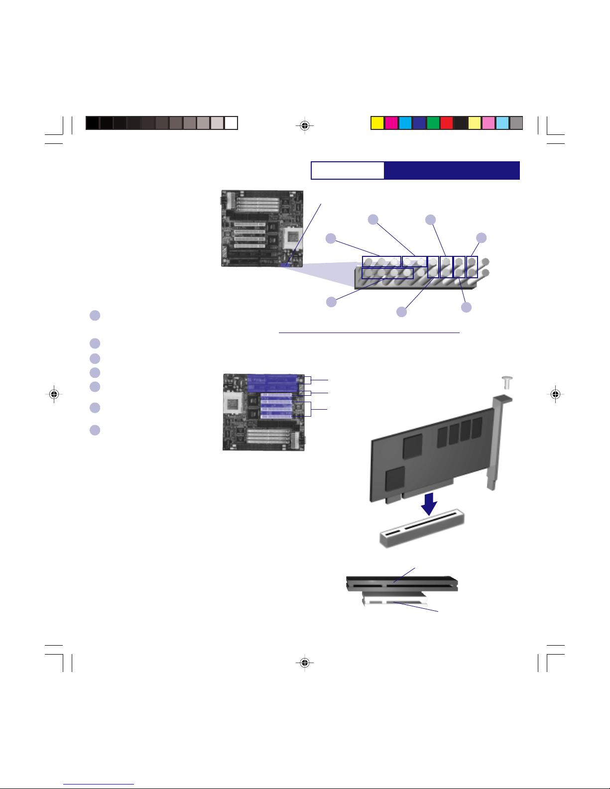
Installing a VGA Adapter
The P5VPX97 provides 3 PCI, 2 ISA, and
1 PCI/ISA expansion slots. Although
other peripherals may be installed at this
time, we recommend that you first start
with the Video Graphics Adapter. Since
other peripherals are not necessarily
needed for initial setup purposes, we will
only give examples of installing a VGA
adapter.
Note: For installation of SCSI, Internal
Modem, Audio, or any other peripherals,
please refer to the respective
manufacturer’s instructions.
Key Lock
(Connection to the keyboard lock switch)
ON - Keyboard is locked out
OFF - Normal operation
Power LED indicator
(On when the board is supplied power)
Speaker
(Internal speaker connection)
Turbo LED
(On when in turbo mode)
HDD Activity
(On when there is Hard Disk Drive
Activity)
Reset
(Connection to the reset switch)
Shorted to invoke a hardware reset
Ext. SMI
(Connection to the suspend switch)
Shorted to place the system into a
suspend mode or “Green” mode.
G
F
E
D
C
B
A
About The VGA Adapter
The P5VPX97 supports either PCI or ISA
types of VGA adapters. For best
performance, we recommend you to use a
PCI VGA Adapter. Using an ISA adapter
will reduce overall performance in a
Windows environment.
16-bit ISA Expansion
Slot
32-bit PCI Expansion
Slot
16-bit ISA Expansion
Slots
Shared (one or the other)
ISA/PCI Expansion Slot
32-bit PCI Expansion
Slots
1. Locate an available PCI or ISA
expansion slot.
2. Mount the VGA adapter on to an
expansion slot.
3. Use a screw to anchor the adapter
to the chassis.
You are now ready to boot the
computer for the first time.
Please continue to the next section to
configure your BIOS (Basic Input
Output System) Settings. It must be
configured for booting.
Reset
F
P5VPX97-AT.p65 6/16/98, 3:31 PM13
P5VPX97-AT
Entering Setup
Power on the computer and press <Del> immediately to allow you to enter Setup. The other way to enter
Setup is to power on the computer, when the below message appears briefly at the bottom of the screen
during the POST (Power On Self Test),press<Del> key or simultaneously press <Ctrl>,<Alt>,and<Esc> keys.
TO ENTER SETUP BEFORE BOOT PRESS : <CTRL-ALT-ESC>OR<DEL>KEY
If the message disappears before you respond, restart the system by turning it OFF then ON or pressing the
RESET button on the system case. You may also restart by simultaneously pressing <Ctrl>,<Alt>, and
<Delete> keys. If you do not press the keys at the correct time and the system does not boot, an error
message will be displayed and you will again be asked to,
PRESS <F1> TO CONTINUE, <CTRL-ALT-ESC> OR <DEL>TO ENTER SETUP
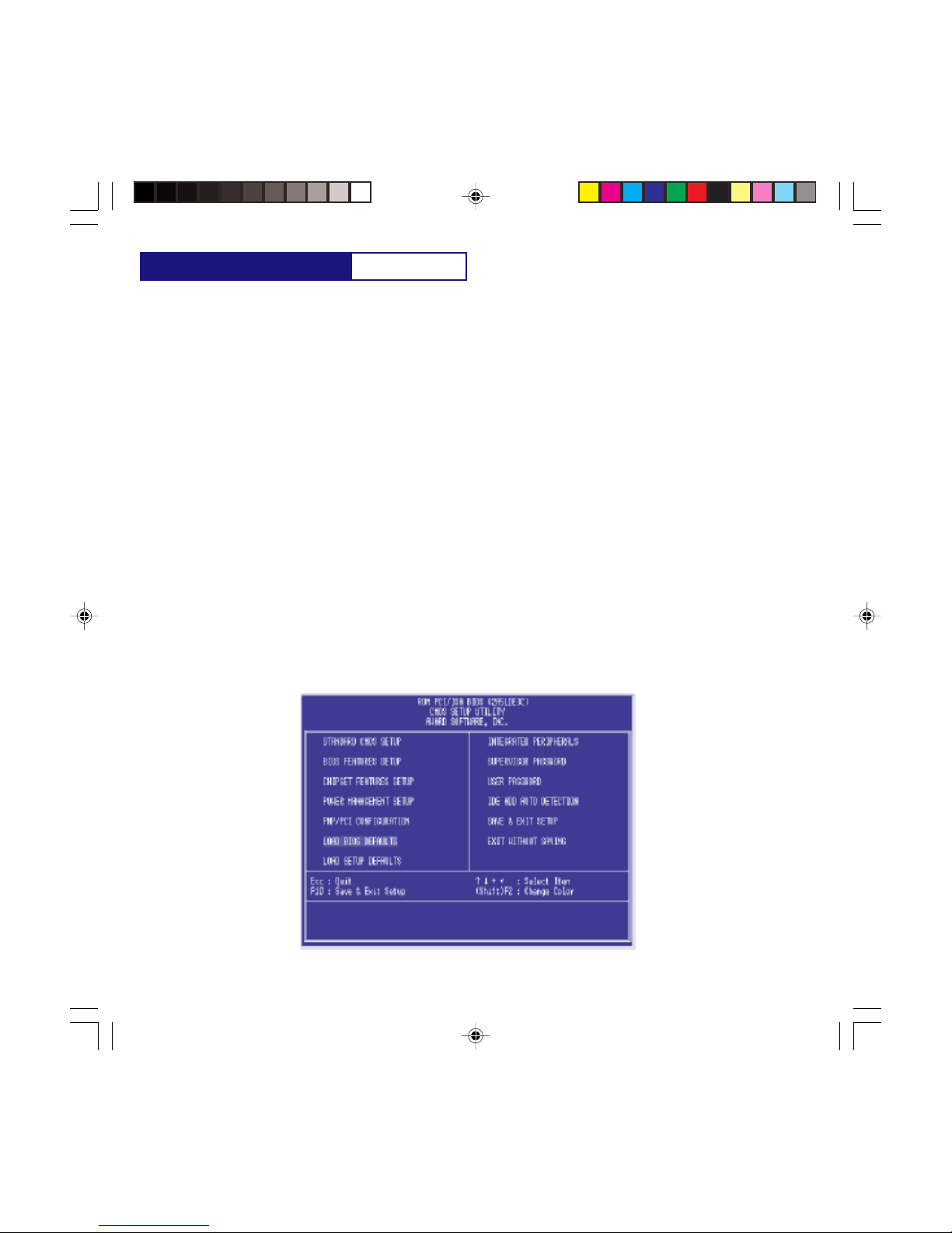
The Main Menu
Once you enter Award BIOS CMOS Setup Utility, the Menu will appear on the screen. The Main Menu allows
you to select from ten setup functions and two exit choices. Use arrow keys to select among the items and
press
<Enter> to accept or enter the sub-menu.
AWARD BIOS SETUP
P5VPX97-AT.p65 6/16/98, 3:31 PM14

P5VPX97-AT
STANDARD CMOS SETUP
This setup page includes all the items in a standard compatible BIOS.
BIOS FEATURES SETUP
This setup page includes all the items of Award special enhanced features.
CHIPSET FEATURES SETUP
This setup page includes all the items of chipset special features.
POWER MANAGEMENT SETUP
This category determines how much power consumption for system after selecting below items. Default value is
Disable.
PNP/PCI CONFIGURATION SETUP
This category specifies the value (in units of PCI bus clocks )of the latency time for this PCI bus master and the
IRQ level for a PCI device.
LOAD BIOS DEFAULTS
BIOS defaults indicates the most appropriate value of the system parameter which the system would be in
minimum performance.
LOAD SETUP DEFAULTS
Chipset defaults indicates the values required by the system for the maximum performance
INTEGRATED PERIPHERALS
IDE, FDD, Serial, parallel port I/O configuration.
SUPERVISOR & USER PASSWORD SETTING
Change, set, or disable password. It allows you to limit access to the system and Setup.
IDE HDD AUTO DETECTION
Automatically configure hard disk parameters.
SAVE & EXIT SETUP
Save CMOS value changes to CMOS and exit setup.
EXIT WITHOUT SAVE
Abandon all CMOS value changes and exit setup.
AWARD BIOS SETUP
P5VPX97-AT.p65 6/16/98, 3:31 PM15

P5VPX97-AT
The above screen provides you with a list of options. At the bottom of this screen are the control keys for use
on this screen. Take note of these keys and their respective uses.
User-configurable fields appear in a different color. If you need information on the selected field, press the
<F1> key. The help menu will them appear to provide you with the information you need. The memory
display at the lower right-hand side of the screen is read-only and automatically adjusts accordingly.
Standard CMOS Setup Menu
The items in Standard CMOS Setup Menu are divided into 10 categories. Each category includes no, one or
more than one setup items. Use the arrow keys to highlight the item and then use the <PgUp> or <PgDn>
keys to select the value you want in each item.
Date
To set the date, highlight the Date field and then press the page up/page down or +/- keys to set the
current date. Follow the month, day and year format. Valid values for month, day and year are:
Month: 1 to 12
Day: 1 to 31
Year: up to 2099
AWARD BIOS SETUP
P5VPX97-AT.p65 6/16/98, 3:31 PM16

P5VPX97-AT
Time
To set the time, highlight the Time field and then press the page up/page down or +/- keys to set the
current time. Follow the hour, minute and second format. Valid values for hour, minute and second are:
Hour: 00 to 23
Minute: 00 to 59
Second: 00 to 59
You can bypass the date and time prompts by creating an AUTOEXEC.BAT file. For information on how to
create this file, please refer to an MS-DOS manual.
Hard Disk Drives
This field records the specifications for all non-SCSI hard disk drives installed in your system. The onboard PCI
IDE connectors provide Primary and Secondary channels for connecting up to four IDE hard disks or other
IDE devices. Each channel can support up to two hard disks; the first of which is the master and the
second is the slave.
Specifications for SCSI hard disks need not to be entered here since they operate using device drivers and
are not supported by any the BIOS. If you install other vendors SCSI controller card, please refer to their
respective documentations on how to install the required SCSI drivers.
To enter specifications for a hard disk drive, you must select first a type. You can select User and specify
the specifications yourself manually, or you can select from the provided predefined drive specifications. To
select, simply press the <Page Up> or <Page Down> key to change the option listed after the drive letter.
For IDE hard disk drive setup, you can:
Use the Auto setting for detection during bootup.
Use the IDE HDD AUTO DETECTION in the main menu to automatically enter the drive specifications. ·
Enter the specifications yourself manually by using the User option.
The entries for specifying the hard disk type include CYLS (number of cylinders), HEAD (number of read/write
heads),PRECOMP (write precompensation), LANDZ (landing zone), SECTOR (number of sectors) and MODE.
The SIZE field automatically adjusts according to the configuration you specify, The documentation that
comes with your hard disk should provide you with the information regarding the drive specifications.
The MODE entry is for IDE hard disks only, and can be ignored for MFM and ESDI drives. This entry provides
three options: Normal, Large, LBA, or Auto (see below). Set MODE to the Normal for IDE hard disk drives
smaller than 528MB; set it to LBA for drives over 528MB that support Logical Block Addressing (LBA) to allow
larger IDE hard disks; set it to Large for drives over 528MB that do not support LBA. Large type of drive can
only be used with MS-DOS and is very uncommon. Most IDE drives over 528MB support the LBA mode.
AWARD BIOS SETUP
P5VPX97-AT.p65 6/16/98, 3:31 PM17

P5VPX97-AT
Auto detection of hard disks on bootup
For each field: Primary Master, Primary Slave, Secondary Master, and Secondary Slave, you can select Auto
under the TYPE and MODE fields. This will enable auto detection of your IDE drives during bootup. This will allow
you to change your hard drives (with the power off) and then power on without having to reconfigure your
hard drive type. If you use older hard drives which do not support this feature, then you must configure the
hard drive in the standard method as described above by the User option.
NOTE: After the IDE hard disk drive information has been entered into BIOS, new IDE hard disk drives must be
partitioned (such as with FDISK) and then formatted before data can be read from and write on. Primary IDE
hard disk drives must have its partition set to active (also possible with FDISK).
NOTE: SETUP Defaults are noted in parenthesis next to each function heading.
Drive A/Drive B (None)
These fields record the types of floppy disk installed in your system. The available options for drives A and B are:
360KB, 5.25in.; 1.2MB, 5.25in,; 720KB, 3.5in,; 1.44MB, 3.5in,;None.
To enter the configuration value for a particular drive, highlight its corresponding field and then select the drive
type using the left-or right-arrow key.
Floppy 3 Mode Support (Disabled)
This is the Japanese standard floppy drive. The standard stores 1.2MB in a 3.5 diskette. This is normally
disabled but you may choose from either: Drive A, Drive B, Both, and Disabled.
Video (EGA/VGA)
Set this field to the type of video display card installed in your system. The options are: EGA/VGA, Mono (for
Hercules or MDA), CGA 40, and CGA 80.
If you are using a VGA or any higher resolution card, choose the EGA/VGA option.
Halt On (All Errors)
This field determines which types of errors will cause the system to halt. Choose from: All Errors, No Errors,
All, But Keyboard, All, But Diskette, and All, But Disk/Key.
AWARD BIOS SETUP
P5VPX97-AT.p65 6/16/98, 3:31 PM18
P5VPX97-AT
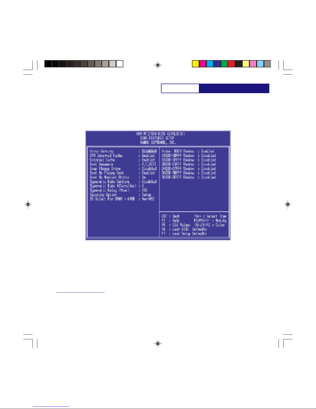
BIOS Features Setup
This BIOS Features Setup option consists of configuration entries that allow you to improve your system
performance, or let you set up some system features according to your preference. Some entries here are
required by the motherboards design to remain in their default settings.
A section at the lower right of the screen displays the control keys you can use. Take note of these keys and
their respective uses. If you need information on a particular entry, highlight it and then press the <F1> key.
A pop-up help menu will appear to provide you with the information you need. To load the last set values,
press the <F5> key. <F6> and <F7> load the BIOS default values and Setup default values, respectively.
NOTE: SETUP Defaults are noted in parenthesis next to each function heading.
Virus Warning (Disabled)
This field protects the boot sector and partition table of your hard disk against accidental modifications. Any
attempt to write to them will cause the system to halt and display a warning message. If this occurs, you can
either allow the operation to continue or use a bootable virus-free floppy disk to reboot and investigate your
system. This setting is recommended because conflicts with new operating systems. Installation of new
operating systems require that you disable this to prevent write errors.
AWARD BIOS SETUP
P5VPX97-AT.p65 6/16/98, 3:31 PM19

P5VPX97-AT
CPU Internal Cache (Enabled)
This option allows you to enable/disable CPU internal cache.
External Cache (Enabled)
This option allows you to enable/disable CPU external cache.
Boot Sequence (A,C,SCSI)
This field determines where the system looks first for an operating system. Options are A, C, SCSI ; C, A, SCSI ;
C, CDROM, A ; CDROM, C, A ; D, A, SCSI ; E, A, SCSI ; F, A, SCSI ; SCSI, A, C ; SCSI, C, A ; C only;LS/ZIP,C The
setup default setting is to check first the hard disk and then the floppy drive; that is A,C,SCSI.
Swap Floppy Drive (Disabled)
When enabled, the BIOS swaps floppy drive assignments so that Drive A becomes Drive B, and Drive B
becomes Drive A under DOS.
Boot Up Floppy Seek (Enabled)
When enabled, the BIOS will seek the floppy A drive one time.
Boot Up NumLock Status (On)
This field enables users to activate the NumberLock function upon system boot.
Typematic Rate Setting (Disabled)
When enabled, you can set the two typematic controls listed next. Setup default setting is Disabled.
Typematic Rate [Chars/Sec] (6)
This field controls the speed at which the system registers repeated keystrokes. Options range from 6 to 30
characters per second. Setup default setting is 6; other settings are 6, 8, 10, 12, 15, 20, 24 and 30.
Typematic Delay (Msec) (250ms)
This field sets the time interval for displaying the first and second characters. Four delay rate options are
available: 250ms, 500ms, 750ms and 1000ms.
Security Option (Setup)
This field determines when the system prompts for the password. The default setting is System, where the
system prompts for the User Password every time you boot up. The other option is Setup, where the system
always boots up, and prompts for the Supervisor Password only when the Setup utility is called up. You can
specify a password by using the Supervisor Password or User Password option from the main screen as
explained later in this section.
Video BIOS Shadow
It determines whether video BIOS will be copied to system RAM, however, it is optional from chipset design.
Video Shadow will increase the video speed.
OS/2 Select For DRAM > 64M (Non-OS2)
When using OS/2 operating systems with installed DRAM of greater than 64MB, you need to Enable this
option otherwise leave this on the setup default of Non-OS2.
AWARD BIOS SETUP
P5VPX97-AT.p65 6/16/98, 3:31 PM20
Table of contents
Other EFA Motherboard manuals


