EFA P5V580-AT-C User manual

_____________________________________________________________
P5V580-AT-C M/B Manual Page 1
P5V580-AT-C
ISA/PCI/IO
Mother Board
User’s Manual
PART NO. M523G0010C Rev 1.0 AUG. 1997

_____________________________________________________________
Page 2P5V580-AT-C M/B Manual
TABLE OF CONTENTS
1. SPECIFICATION .................................................................................. 2
2.
JUMPER SETTING ............................................................................... 3
2.1 Table of Jumper Setting .................................................................... 3
CPU Jumper Setting .......................................................................... 3
Memory Size ...................................................................................... 4
Special Function Jumpers .................................................................. 5
2.2 Chart of Jumper .................................................................................. 6
3.
AWARD BIOS SETUP ........................................................................... 7
3.1 Entering Setup ................................................................................... 7
3.2 The Main Menu ................................................................................. 8
3.3 Standard CMOS Setup Menu ............................................................ 10
3.4 BIOS Features Setup Menu ............................................................... 13
3.5 Chipset Features Setup Menu ........................................................... 16
3.6 Power Management Setup Menu ...................................................... 17
3.7 PNP/PCI Configuration Setup Menu ................................................ 20
3.8 Integrated Peripherals ....................................................................... 22
3.9 Supervisor Password & User Password Setting ................................ 24
3.10 IDE HDD Auto Detection ............................................................... 25
3.11 Power On Boot ................................................................................ 28
3.12 BIOS Reference - POST Message ................................................... 29

_____________________________________________________________
P5V580-AT-C M/B Manual Page 3
1. SPECIFICATIONS
1. P5V580-AT SPECIFICATIONS
CPU CPU Intel Pentium P54C / P54CS / P55C
Cyrix 6x86 / 6x86L / 6x86MX
AMD K5 / K6
CPU Speed P54C : 75/90/100/120/133/150/166/200MHz;
P55C : 166/200/233MHz
System Speed 50/55/60/66/75MHz
BIOS BIOS 128K BIOS; PnP Compliant
BIOS ROM Flash Memory
CACHE Internal (L1) Write Back
External (L2) Pipe-line Burst Write Back SRAM(256K/512K)
MEMORY DRAM Size From 8M up to 256M Bytes
DRAM Module SIMM x 4 for 2 Banks of 72 Pin
DIMM x 1 of 168 Pin for 3.3V Sync. and EDO DRAM
Data Path 64 Bit Wide
On Board I/O I/O Function Local Bus Enchanced Dual-Channel IDE
Bus Master PCI IDE /Mode 4 Support
ECP/EPP Parallel Port
2 Serial Port
IR Function (Optional)
FDD Support
GREEN SYSTEM SMM Control, Stop CPU Clock
VGA Control of DPMS
SLOT Expansion Slot 16 Bit ISA x 4
32 Bit PCI x 3 (3 Master Support)
PCI Bus Fully Synchronous 25/27.5/30/33/37.5MHz PCI Bus
Interface
MEMORY DIMM x 1 + SIMM x 4
Mouse PS/2 Mouse
Keyboard Keyboard CNN AT Keyboard
Others Main Chipset VIA 580VPX CHIPSET
IO Chipset SMC669
PCB Size 220mm x 230mm x 1.6mm, 4 layers
_____________________________________________________________
Page 4P5V580-AT-C M/B Manual
2.JUMPER SETTING
2. JUMPER SETTING
2.1. Table of Jumper Setting
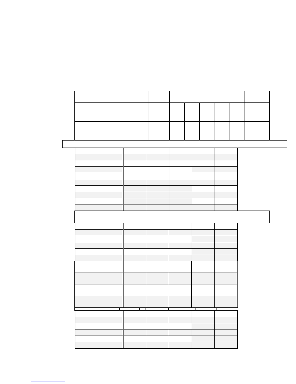
lCPU Voltage Select (* : reserve)
CPU TYPE JP1 JP9
A B C D E
VCORE
* * OFF OFF OFF OFF ON 2.1V
PENTIUM MMX/Cyrix 6x86L 3-5/4-6 OFF ON OFF OFF OFF 2.8V
Cyrix 6x86MX/AMD K6(166-200) 3-5/4-6 OFF ON OFF OFF ON 2.9V
AMD K6(233) 3-5/4-6 OFF ON ON OFF OFF 3.2V
PENTIUM 1-3/2-4 OFF ON ON OFF ON 3.3V
Cyrix 6x86/AMD K5 1-3/2-4 OFF ON ON ON ON 3.5V
lCPU Jumper Setting
INTEL JP6 JP7 JP8 JP2 JP3
75MHz 2-3 2-3 2-3 OFF OFF
90MHz OFF OFF
120MHz 2-3 2-3 1-2 OFF ON
150MHz ON ON
100MHz OFF OFF
133MHz OFF ON
166MHz 2-3 1-2 2-3 ON ON
200MHz ON OFF
233MHz OFF OFF
²If select Cyrix CPU, JP10 must be set ON and select 6x86L-P200+ / 6x86MX-
PR200 75MHz, JP5 must be set 2-3
Cyrix JP6 JP7 JP8 JP2 JP3
6x86-P120+2-3 2-3 2-3
6x86-P133+1-2 2-3 2-3
6x86-P150+2-3 2-3 1-2 OFF ON
6x86/6x86L-P166+2-3 1-2 2-3
6x86L-P200+1-2 2-3 1-2
6x86MX- PR166
60MHz Bus 2.5x 2-3 2-3 1-2 ON ON
6x86MX- PR166
66MHz Bus 2x 2-3 1-2 2-3 OFF ON
6x86MX- PR200
66MHz Bus 2.5x 2-3 1-2 2-3 ON ON
6x86MX- PR200
75MHz Bus 2x 1-2 2-3 1-2 OFF ON
AMD JP6 JP7 JP8 JP2 JP3
K5 -PR75 2-3 2-3 2-3
K5 -PR90 2-3 2-3 1-2
K5 -PR100 2-3 1-2 2-3 OFF OFF
K5 -PR120 2-3 2-3 1-2
K5 -PR133 2-3 1-2 2-3

_____________________________________________________________
P5V580-AT-C M/B Manual Page 5
K5 -PR150 2-3 2-3 1-2 ON ON
K5 -PR166 2-3 1-2 2-3 ON ON
K6-166 2-3 1-2 2-3 ON ON
K6-200 2-3 1-2 2-3 ON OFF
K6-233 2-3 1-2 2-3 OFF OFF
2. JUMPER SETTING
lMemory Size
²168 PIN DIMM & 72 PIN SIMM
Option Type
Bank0/1 8M, 16M, 32M, 64M
Bank2/3 4M/4M,8M/8M,16M/16M,32M/32M,64M/64M
Bank4/5 4M/4M,8M/8M,16M/16M,32M/32M,64M/64M
NOTE :1 > 4M :[ 1Mx(32/36)bit]2
8M :[ 2Mx(32/36)bit]2
16M :[ 4Mx(32/36)bit]2
32M :[ 8Mx(32/36)bit]2
64M :[16Mx(32/36)bit]2
2 > The DRAM interface supports 8Mbytes to 256 Mbytes
3 > For access time SIMM, must use 70us or less.
4 > The DRAM modules installed to the same memory bank
need to be consistent. But the combinations of different
memory size of Bank 1 and Bank 2 are accepted.
5 > Bank 0/1 support 168pin 3.3V Sync. and EDO DRAM.
6 >
Bank 2/3/4/5 support 72 pin 5V EDO and fast page mode
DRAM
_____________________________________________________________
Page 6P5V580-AT-C M/B Manual
2.JUMPER SETTING
lSpecial Function Jumpers
Jumper Number FUNCTION
J1 K/B CONNECTOR
J2 PS/2 MOUSE
J6 IR
COM 1 COM PORT 1
COM 2 COM PORT 2
IDE 1 IDE 1
IDE 2 IDE 2
FDC 1 FDD
LPT 1 PRINT PORT 1
JP4 CMOS CLEAR
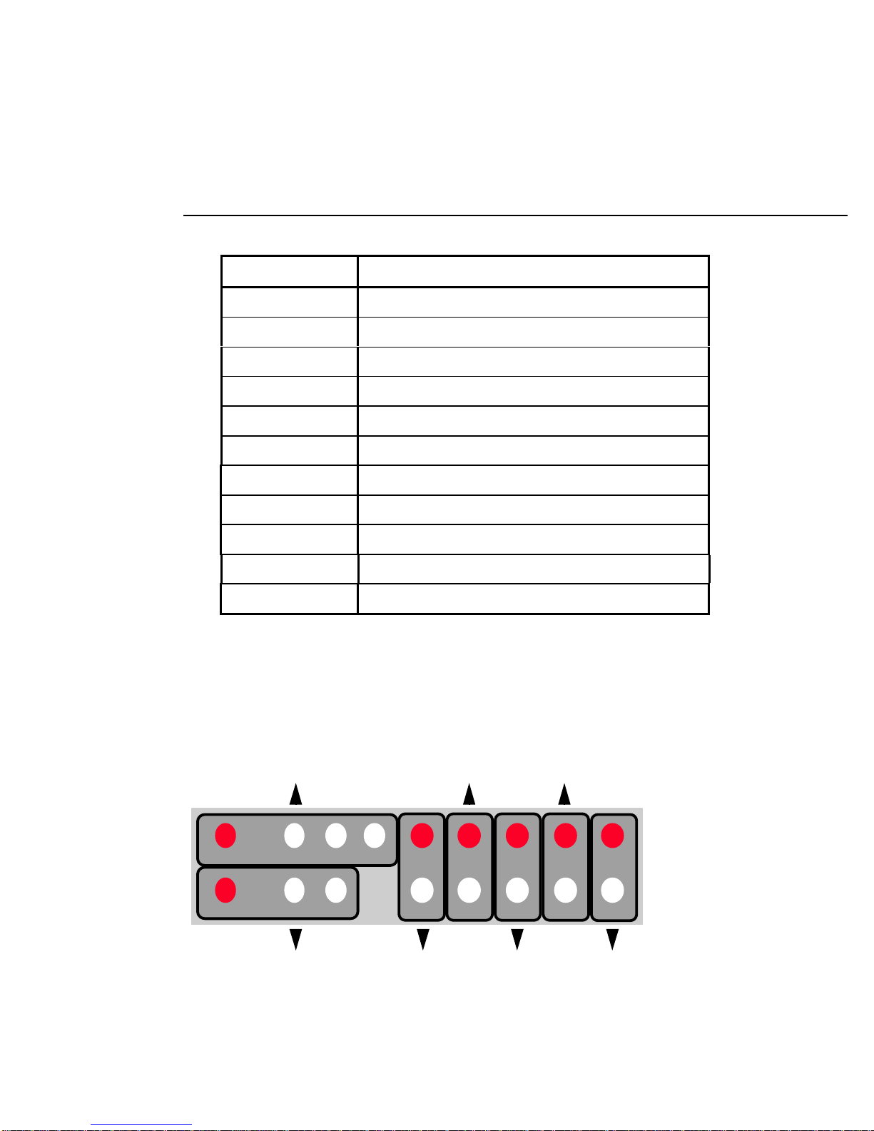
J7 MULTIFUNCTION CONNECTOR
lMultifunction Connector
Power LED/Key Lock
Speaker Turbo
LED
Ext_SMI
HDD
LED
Reset
Green
LED
+
++ + + + +
_____________________________________________________________
P5V580-AT-C M/B Manual Page 7
2. JUMPER SETTING
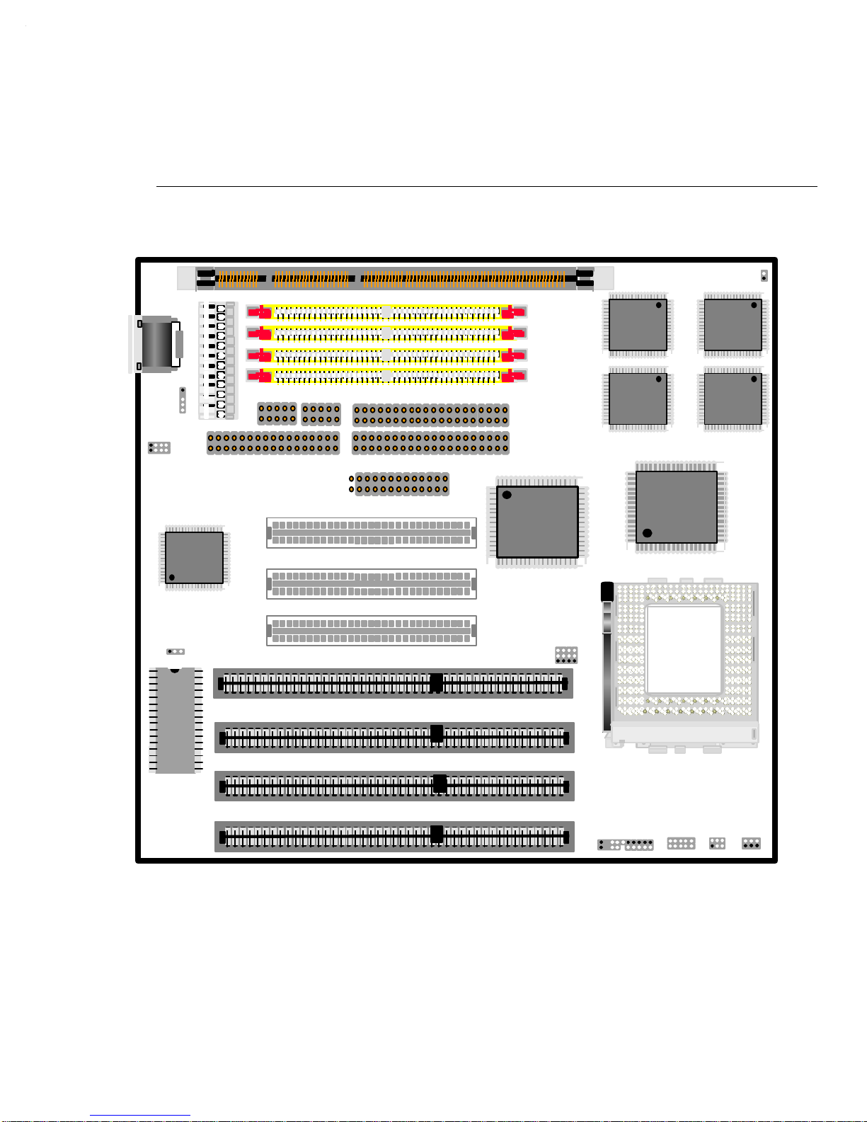
2.2 Chart of jumper
JUMPER OUTLINE
VT
82C587VP
VT
82C587VP 64KX32
64KX32
SMC669
VT
82C586VP
PCI1
PCI2
PCI3
VT
82C585VP
JP5/6/7/8
J7
BIOS
JP4 SL1
SL2
SL3
SL4
LPT1
BANK5
BANK4
BANK3
BANK2
FDD IDE2
IDE1
COM1/2
BANK0/1 JP10
JP3/2/11
JP9
ABCDE
JP1
135
J4
J5
J1
J2

_____________________________________________________________
Page 8P5V580-AT-C M/B Manual
3. AWARD BIOS SETUP
3. AWARD BIOS SETUP
3.1 Entering Setup
Power on the computer and press <Del> immediately to allow you to enter Setup. The other way to
enter Setup is to power on the computer, when the below message appears briefly at the bottom of
the screen during the POST (Power On Self Test), press <Del> key or simultaneously press <Ctrl>,
<Alt>, and <Esc> keys.
TO ENTER SETUP BEFORE BOOT PRESS : <CTRL-ALT-ESC> OR <DEL> KEY
If the message disappears before you respond, restart the system by turning it OFF then ON or
pressing the "RESET" button on the system case. You may also restart by simultaneously pressing
<Ctrl>, <Alt>, and <Delete> keys. If you do not press the keys at the correct time and the system
does not boot, an error message will be displayed and you will again be asked to,
PRESS <F1> TO CONTINUE, <CTRL-ALT-ESC> OR <DEL> TO ENTER SETUP

_____________________________________________________________
P5V580-AT-C M/B Manual Page 9
3.AWARD BIOS SETUP
3.2 The Main Menu
Once you enter Awoard BIOS CMOS Setup Utility, the Main Menu (Figure 1) will appear on the
screen. The Main Menu allows you to select from ten setup functions and two exit choices. Use
arrow keys to select among the items and press <Enter> to accept or enter the sub-menu.
STANDARD CMOS SETUP
This setup page includes all the items in a standard compatible BIOS.
BIOS FEATURES SETUP
This setup page includes all the items of Award special enhanced features.
CHIPSET FEATURES SETUP
This setup page includes all the items of chipset special features.
POWER MANAGEMENT SETUP
This category determines how much power consumption for system after selecting below items.
Default value is Disable.
PNP/PCI CONFIGURATION SETUP
This category specifies the value (in units of PCI bus clocks) of the latency time for this PCI bus
master and the IRQ level for a PCI device.

_____________________________________________________________
Page 10 P5V580-AT-C M/B Manual
3.AWARD BIOS SETUP
LOAD BIOS DEFAULTS
BIOS defaults indicates the most appropriate value of the system parameter which the system would
be in minimum performance.
LOAD SETUP DEFAULTS
Chipset defaults indicates the values required by the system for the maximum performance.
INTEGRATED PERIPHERALS
IDE, FDD, Serial, Parallel port I/O configuration.
SUPERVISOR & USER PASSWORD SETTING
Change, set, or disable password. It allows you to limit access to the system and Setup.
IDE HDD AUTO DETECTION
Automatically configure hard disk parameters.
HDD LOW LEVEL FORMAT
To perform low level format of hard disk drive.
SAVE & EXIT SETUP
Save CMOS value changes to CMOS and exit setup.
EXIT WITHOUT SAVE
Abandon all CMOS value changes and exit setup.

_____________________________________________________________
P5V580-AT-C M/B Manual Page 11
3.AWARD BIOS SETUP
3.3 Standard CMOS Setup Menu
The items in Standard CMOS Setup Menu are divided into 10 categories. Each category includes
no, one or more than one setup items. Use the arrow keys to highlight the item and then use the
<PgUp> or <PgDn> keys to select the value you want in each item.
Date
The date format is <day>, <date> <month> <year>.
day The day of week, from Sun to Sat, determined by the BIOS, is read only
date The date, from 1 to 31 (or the maximum allowed in the month), can key in
the numerical / function key
month The month, Jan through Dec
year The year, depends on the year of BIOS
Time
The time format is <hour> <minute> <second>. The time is calculated based on the 24-hour
military-time clock. For example, 1 p.m. is 13:00:00.

_____________________________________________________________
Page 12 P5V580-AT-C M/B Manual
3.AWARD BIOS SETUP
Primary Master/Primary Slave/Secondary Master/Secondary Slave
The category identifies primary and secondary channels. Type User is user- definable, you can select
“AUTO”, the system will be automatically detect harddisk type.
Press PgUp/<+> or PgDn/<symbol 45 \f "Symbol" \s 10.5
−
> to select a numbered hard disk type or
type the number and press <Enter>. Note that the specifications of your drive must match with the
drive table. The hard disk will not work properly if you enter improper information for this
category. If your hard disk drive type is not matched or listed, you can use Type User to define your
own drive type manually.
If you select Type User, related information is asked to be entered to the following items. Enter the
information directly from the keyboard and press <Enter>. This information should be provided in
the documentation from your hard disk vendor or the system manufacturer.
If the controller of HDD interface is SCSI, the selection shall be “None”.
If the controller of HDD interface is CD-ROM, the selection shall be “None”.
CYLS.
number of cylinders
HEADS
number of heads
PRECOMP
write precomp
LANDZONE
landing zone
SECTORS
number of sectors
MODE
HDD access mode
If a hard disk has not been installed select NONE and press <Enter>.
Drive A type/Drive B type
The category identifies the types of floppy disk drive A or drive B that have been installed in the
computer.
None No floppy drive installed
360K, 5.25 in 5-1/4 inch PC-type standard drive; 360 kilobyte capacity
1.2M, 5.25 in 5-1/4 inch AT-type high-density drive; 1.2 megabyte capacity
720K, 3.5 in 3-1/2 inch double-sided drive; 720 kilobyte capacity
1.44M, 3.5 in 3-1/2 inch double-sided drive; 1.44 megabyte capacity
2.88M, 3.5 in 3-1/2 inch double-sided drive; 2.88 megabyte capacity

_____________________________________________________________
P5V580-AT-C M/B Manual Page 13
3.AWARD BIOS SETUP
Video
The category selects the type of adapter used for the primary system monitor that must match your
video display card and monitor. Although secondary monitors are supported, you do not have to
select the type in Setup.
There are two ways to boot up the system:
1. When VGA as primary and monochrome as secondary, the selection of the video type is “VGA
Mode”
2. When monochrome as primary and VGA as secondary, the selection of the video type is
“Monochrome Mode”.
EGA/VGA Enhanced Graphics Adapter/Video Graphics Array. For EGA, VGA, SVGA, or PGA
monitor adapters.
CGA 40 Color Graphics Adapter, power up in 40 column mode
CGA 80 Color Graphics Adapter, power up in 80 column mode
MONO Monochrome adapter, includes high resolution monochrome adapters
Error halt
The category determines whether the computer will stop if an error is detected during power up.
No errors Whenever the BIOS detects a non-fatal error the system will be stopped and you
will be prompted.
All errors The system boot will not be stopped for any error that may be detected.
All,But Keyboard The system boot will not stop for a keyboard error; it will stop for all other errors.
All, But Diskette The system boot will not stop for a disk error; it will stop for all other errors.
All, But Disk/Key The system boot will not stop for a keyboard or disk error; it will stop for all other
errors.
Memory
The category is display-only which is determined by POST Self Test) of the BIOS.
symbol 254 \f "MS LineDraw" \s 10.5} Base Memory
The POST of the BIOS will determine the amount of base (or conventional) memory installed in the
system. The value of the base memory is typically 512K for systems with 512K memory installed
on the motherboard, or 640K for systems with 640K or more memory installed on the motherboard.
symbol 254 \f "MS LineDraw" \s 10.5} Extended Memory
The BIOS determines how much extended memory is present during the POST. This is the amount
of memory located above 1MB in the CPU's memory address map.
symbol 254 \f "MS LineDraw" \s 10.5} Other Memory
This refers to the memory located in the 640K to 1024K address space. This is memory that can be
used for different applications. DOS uses this area to load device drivers to keep as much base
memory free for application programs. Most use for this area is Shadow RAM.
symbol 254 \f "MS LineDraw" \s 10.5} Total Memory
System total memory is the sum of basic memory, extended memory, and other memory.
_____________________________________________________________
Page 14 P5V580-AT-C M/B Manual
3.AWARD BIOS SETUP
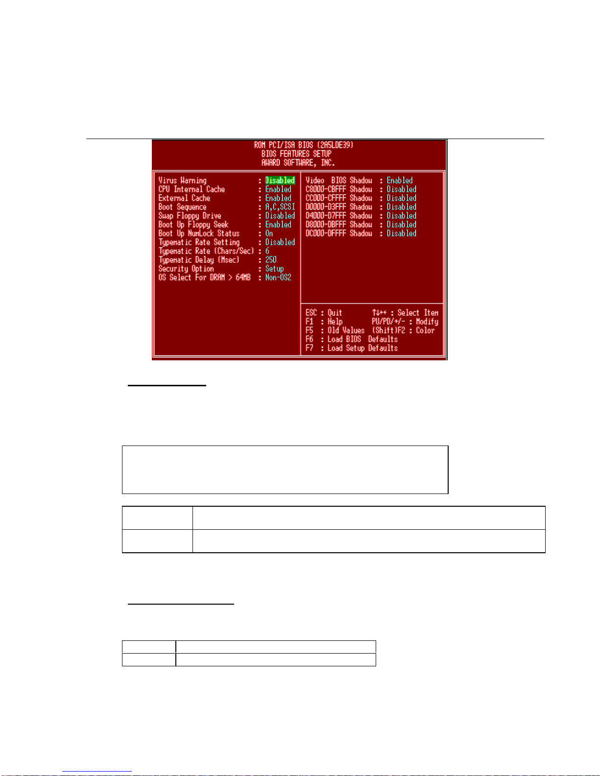
3.4BIOS Features Setup Menu
Virus Warning
This category flashes on the screen. During and after the system boots up, any attempt to write to
the boot sector or partition table of the hard disk drive will halt the system and the following error
message will appear, in the mean time, you can run an anti-virus program to locate the problem.
! WARNING !
Disk boot sector is to be modified
Type "Y" to accept write or "N" to abort write
Award Software, Inc.
Enabled Activates automatically when the system boots up causing a warning message to
appear when anything attempts to access the boot sector or hard disk partition table.
Disabled No warning message to appear when anything attempts to access the boot sector or
hard disk partition table.
Note: This function is available only for DOS and other OSes that do not trap INT13.
CPU Internal Cache
These two categories speed up memory access. The default value is Enable.
Enabled Enable cache
Disabled Disable cache

_____________________________________________________________
P5V580-AT-C M/B Manual Page 15
3.AWARD BIOS SETUP
External Cache
The External Cache selection enables or disables the external (L2) cache and the onboard secondary
cache. The default setting is Enabled.
Enabled Enable external cache
Disabled Disable external cache
Boot Sequence
This category determines which drive the computer searches first for the disk operating system
(i.e., DOS). Default value is A,C,SCSI.
Boot Sequence:
1. A, C, SCSI 6. E, A, SCSI
2. C, A, SCSI 7. F, A, SCSI
3. C, CDROM, A 8. SCSI, A, C
4. CDROM, C, A 9. SCSI, C, A
5. D, A, SCSI 10. C only
Swap Floppy Drive
This category can change A and B drive.
Enabled Assign A to B & B to A drive.
Disabled Normal.
Boot Up Floppy Seek
During POST, BIOS will determine if the floppy disk drive installed is 40 or 80 tracks. 360K type
is 40 tracks while 760K, 1.2M and 1.44M are all 80 tracks.
Enabled BIOS searches for floppy disk drive to detemine if it is 40 or 80 tracks. Note that BIOS can
not tell from 720K, 1.2M or 1.44M drive type as they are all 80 tracks.
Disabled BIOS will not search for the type of floppy disk drive by track number, Note that there will
not be any warning message if the drive installed is 360K.
Boot Up NumLock Status
The default value is On.
On Keypad is number keys
Off Keypad is arrow keys

_____________________________________________________________
Page 16 P5V580-AT-C M/B Manual
3. AWARD BIOS SETUP
Typematic Rate Setting
This detemines the typematic rate.
Enabled Enable typematic rate and typematic delay programming
Disabled Disable typematic rate and typematic delay programming. The system BIOS will use
default value of this 2 items and the default is controlled by deyboard.
Typematic Rate (Chars/Sec)
66 characters per second
88 characters per second
10 10 characters per second
12 12 characters per second
15 15 characters per second
20 20 characters per second
24 24 characters per second
30 30 characters per second
Typematic Delay (Msec)
250 250 msec
500 500 msec
750 750 msec
1000 1000 msec
Security Option
This category allows you to limit access to the system and Setup, or just to Setup.
System The system will not boot and access to Setup will be denied if the correct password
is not entered at the prompt.
Setup The system will boot, but access to Setup will be denied if the correct password is
not entered at the prompt.
Note: To disable security, select PASSWORD SETTING at Main Menu and then you will be asked
to enter password. Do not type anything and just press <Enter>, it will disable security. Once the
security is disabled, the system will boot and you can enter Setup freely.
Video BIOS Shadow
It determines whether video BIOS will be copied to system RAM, however, it is optional from
chipset design. Video Shadow will increase the video speed.
Enabled Video shadow is enabled
Disabled Video shadow is disabled

_____________________________________________________________
P5V580-AT-C M/B Manual Page 17
3.AWARD BIOS SETUP
3.5 Chipset Features Setup Menu
DRAM Auto Configuration
This option specifies DRAM Timing. If DRAM modules speed symbol 60 \f "Symbol" \s 10.5
<
60ns, please select 60ns. If DRAM modules speed symbol 62 \f "Symbol" \s 10.5
>
70ns, please
select 70ns.
DRAM Timing Control
This option specifies Turbo / Fast / Medium / Normal mode DRAM Timing
Video BIOS Cacheable
The Video BIOS Cache selection allows you to cache the video BIOS for even higher performance.
The default setting is Enabled.
System BIOS Cacheable
The System BIOS Cache selection allows you to cache the system BIOS for even higher
performance. The default setting is Enabled
On-Chip USB
This motherboard supports Universal Serial Bus (USB) devices. This option enbaled or disabled the USB
controller.
USB Keyboard Support
If you are using the USB keyboard should this item be enabled.

_____________________________________________________________
Page 18 P5V580-AT-C M/B Manual
3. AWARD BIOS SETUP
3.6 Power Management Setup
The Power management setup will appear on your screen like this:
This category determines how much power is comsumed. Default value is Disable. The following
pages tell you the options of each item & describe the meanings of each option.
Item Options Descriptions
Power Management 1. Disable Global Power Management
will be disabled
2. User Define Users can configure their
own power management
3. Min Saving Pre-defined timer values are
used such that all timers are
in their MAX value
4. Max Saving Pre-defined timer values are
used such that all timers
MIN value

_____________________________________________________________
P5V580-AT-C M/B Manual Page 19
3.AWARD BIOS SETUP
Item Options Descriptions
PM Control by APM 1. No System BIOS will ignore
APM when power managing
the system
2. Yes System BIOS will wait for
APM’s prompt before it
enter any PM mode e.g.
DOZE, STANDBY or
SUSPEND
Note1: If APM is installed,&
if there is a task
running, even the
timer is time out, the
APM will not prompt
the BIOS to put the
system into any
power saving
modesymbol 33 \f
"Symbol" \s 10.5!
Note2: If APM is not
installed, this option
has no effect.
Video Off Method 1. Blank Screen The system BIOS will only
blank off the screen when
disabling video
2. V/H SYNC + Blank In addition to (1), BIOS will
also turn off the V-
SYNC & H-SYNC signals
form VGA cards to monitor
3. DPMS This function is enabled for
VGA card that support DPM
Note: Green monitors
detect the V/H
SYNC signals to
turn off its electron
gun
MODEM Use IRQ 1. 3
2. 4
3. 5
4. 7
5. 9
6. 10
7. 11
8. NA
Use IRQ 3
Use IRQ 4
Use IRQ 5
Use IRQ 7
Use IRQ 9
Use IRQ 10
Use IRQ 11
Not Use IRQ

_____________________________________________________________
Page 20 P5V580-AT-C M/B Manual
3. AWARD BIOS SETUP
Item Options Descriptions
HDD Power Down 1. Disabled
2. 1-15Mins Shuts down any IDE hard
disk drives in the system
after a period of inactivity.
Doze Mode
(*) Remark 1 1. Disable System will never enter
DOZE mode
2. 1 Min
2 Min
4 Min
6 Min
8 Min
10 Min
20 Min
30 Min
40 Min
1 Hr
Defines the continuous idle
time before the system
enters DOZE mode.
if any item defined in (H) is
enabled & active, DOZE
timer will be reloaded.
Note: Normally,DOZE
mode puts the
system into low
speed or 8MHz,
screen may be
off depending on
Video Off Option
suspend Mode
(*) Remark 1 1. Disable System will never enter
SUSPEND mode
2. 1 Min
2 Min
4 Min
6 Min
8 Min
10 Min
20 Min
30 Min
40 Min
1 Hr
Defines the continuous idle
time before the system
enters SUSPEND mode.
If any item defined in (H) is
enabled & active,
SUSPEND timer will be
reloaded.
Note: Normally,SUSPEND
mode puts the
system into low
speed or 8MHz,
clock is stopped,
screen may be off
depending on
Video Off Option
3. When Suspend BIOS will turn the HDD’s
motor off when system is in
SUSPEND mode
PM Events
VGA/LPT & COM
HDD & FDD
DMA/master
Primary INTR
You can set IRQs 3-15 individually. Activity detected from
any enabled IRQ channel will wake up the system.
* Remark 1: All items mark with (*) in this menu, will be loaded with predefined values as long as
the item ‘Power Management’ is not configured to ‘User Defined’ These items are :
Item ‘System Doze’ & ‘System Suspend’
Table of contents
Other EFA Motherboard manuals


