EFA Viking m3 User manual

Viking m3
(P5MVP3-MATX)
AGP – PCI – ISA – I/O
Motherboard
User’s Manual
PART NUMBER: M563G00100 Rev 1.0JUNE 1998

Viking m3 Manual P5MVP3-MATX Page 1
TABLE OF CONTENTS
1. SPECIFICATIONS 2
2. INSTALLATION GUIDE 3
2.1 Jumper Description 3
2.2 Processor Installation 4
2.3 DIMM Memory Installation 4
2.4 Mounting the Motherboard in the Case
and Connecting the Cables 4
3. JUMPER SETTINGS 6
3.1 CPU Voltage Settings 6
3.2 CPU Jumper Settings 6
3.3 SDRAM Clock Settings 7
3.4 Special Function Jumpers 7
3.5 ATX Form Factor Layout 8
3.6 Multifunction Connector 8
3.7 Memory Size 8
3.8 Jumper Layout Chart 9
4. AWARD BIOS SETUP 10
4.1 Entering Setup 10
4.2 Main Menu 10
4.3 Standard CMOS Setup 11
4.4 BIOS Features Setup 14
4.5 Chipset Features Setup 16
4.6 Power Management Setup 17
4.7 PnP/ PCI Configuration Setup 19
4.8 Load BIOS Defaults 20
4.9 Load Setup Defaults 20
4.10 Integrated Peripherals 21
4.11 Supervisor and User Password 22
4.12 IDE Hard Drive Auto Detection 23
4.13 Save and Exit Setup 23
4.14 Exit Without Saving 23
5. Troubleshooting 24

Viking m3 Manual P5MVP3-MATX Page 2
SPECIFICATIONS
1. P5MVP3-MATX Specifications
CPU CPU Support Intel Pentium /P54C/P54CS/P55C(MMX)
Cyrix 6x86/6x86L/6x86MX/M II
AMD K5/K6/K6-2
CPU Speed P54C:90/100/120/133/150/166/200MHz;
P55C:166/200/233/266/300MHz;
System Speed 60/66/75/83/100MHz
BIOS BIOS 1MB BIOS; PnP Compliant
BIOS ROM Flash Memory
CACHE Internal(L1) Write Back
External(L2) Pipe-line Burst Write Back SRAM(512K/1MB)
MEMORY DRAM Size From 8MB up to 512MB
DRAM Module DIMM x 2 of 168 Pin for Sync. DRAM(3.3V Non-
Buffer or 3.3V EDO)
SIMM x 2 for 1 Bank of 72 Pin (5V EDO / FP)
Data Path 64 Bit Wide
On Board I/O I/O Function Local Bus Enhanced Dual-Channel IDE
Bus Master PCI IDE / Mode 4 Support,
Ultra DMA-33 Mode Supports.
ECP/EPP Parallel Port
2 Serial Port
IR Function (Optional)
FDD Support
GREEN SYSTEM SMM Control, ACPI
VGA Control of DPMS
SLOT Expansion Slot 16 Bit ISA x 1
32 Bit PCI x 3 (4 Master Support)
AGP 1 AGP
Memory DIMM x 2 & SIMM x 2
USB Two USB Ports
Mouse PS/2 Mouse
Keyboard Keyboard CNN PS/2 Keyboard
Others Main Chipset VIA MVP3 Chipset
I/O Chipset SMC669
PCB Size 244mm x 210mm x 1.6mm, 4 layers
Viking m3 Manual P5MVP3-MATX Page 3
1
1
2
5
6
1
3 1 3
INSTALLATION GUIDE
2. Installation Guide
Please follow these steps for proper installation of your high quality EFA motherboard
into your system:
A. Set the jumpers on the motherboard of the type of CPU you will be
installing.
B. Install the Central Processing Unit (CPU or processor).
C. Install the DIMM (Dual Inline Memory Modules).
D. Mount the motherboard in the case.
E. Connect all cables and wires to the motherboard.
F. Install the expansion cards.
Warning: The motherboard and other components contain many IC (Integrated
Circuit) chips. To protect them against damage from static electricity, please pay
attention to the following precautions whenever you are working with computer
components:
1. Unplug the power connector whenever you are working on the interior of the
computer.
2. Hold the motherboard, peripherals, and components by the edges and try not to
touch the IC chips, leads and circuitry.
3. If possible, use a grounded wrist strap when handling the components and place
them on a grounded anti-static pad or anti-static bag when they are pulled from the
computer.
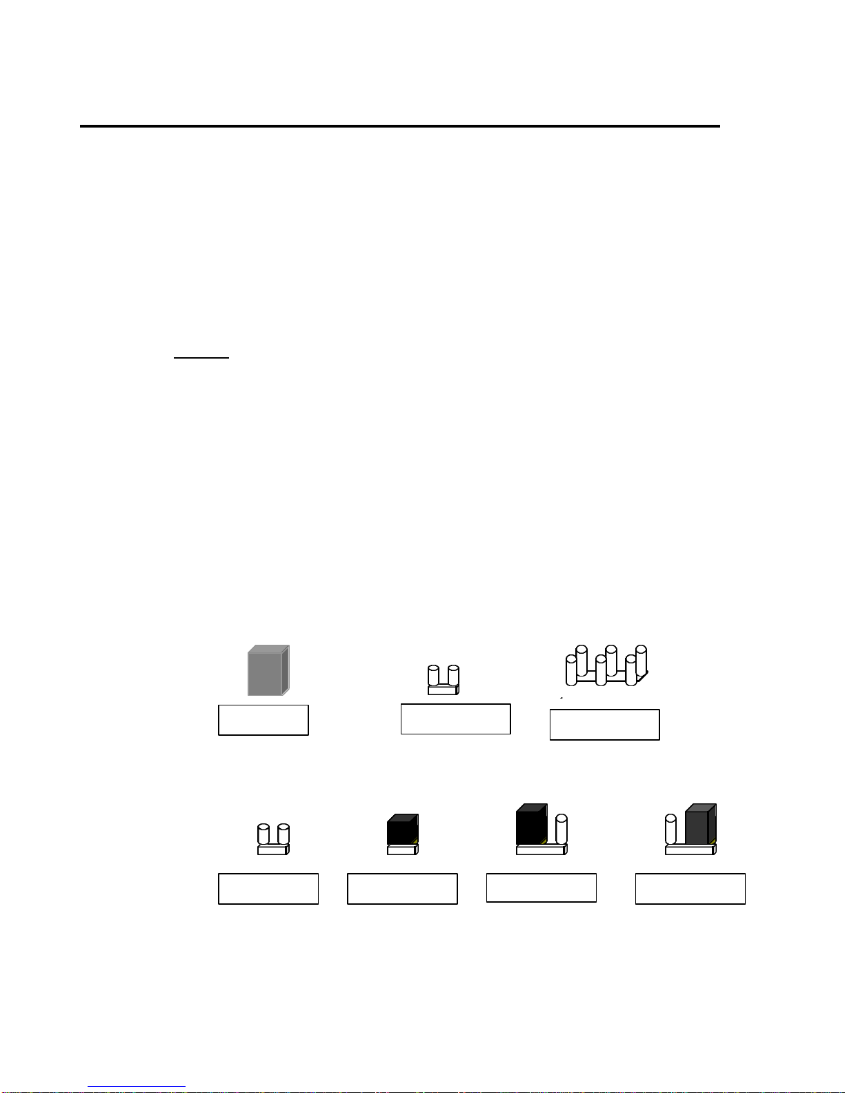
2.1 Jumper Description
Many hardware settings are made through the use of jumper caps connecting the
jumper pins (see the following figures). There are various jumper pins on the
motherboard such as two, three six and eight pin jumpers.
Please refer to the “Table of Jumper Settings“ in the manual. For jumper
examples, see below:
Note: Pin # 1 and the last pin for all the jumpers are silk-screened on the
motherboard.
You should now set the jumpers for the voltage, clock ratio, system clock and
CPU type. Please refer to the Jumper Settings section of this manual.
Pin 1-2 Closed
Pin 2–3 Closed
Jumper Cap 2-pin Jumper 6-pin Jumper
Open Jumper Closed Jumper

Viking m3 Manual P5MVP3-MATX Page 4
INSTALLATION GUIDE
2.2 Processor Installation
Before putting the CPU into the CPU ZIF socket, lift up the locking bar on the
side of the socket, making sure that Pin 1 of the CPU (the corner with the notch)
is facing towards the notch on the CPU socket. Press the CPU firmly into the
socket making sure that it is firmly seated. Continue to push down on the CPU
while lowering the locking bar to lock the CPU in place.
It is always necessary to use a reliable CPU cooling fan with a heat sink.
Most fans will snap onto the ZIF socket.
2.3 DIMM Memory Installation
To install a DIMM module, simply line the notches of the module up with the
notches in the DIMM socket on the motherboard and push the module into the
socket and lock the plastic clips on the ends of the socket. DIMM memory can be
added one at a time.
2.4 Mounting the Motherboard in the Case and Connecting
the Cables
Mounting the Motherboard
Line up the keyboard connector on the motherboard with the keyboard hole on
the case. This should also help you in lining up the mounting holes on the
motherboard. Then use screws to mount the motherboard into the case.
Note: It is important that the motherboard is secure and does not touch the
bare metal of the case. This could cause the motherboard to short.
Power Cable (ATX Power Supply)
Line up the clip on the power cable’s connector with the notch on the ATX jack
on the motherboard and insert the cable in the jack.

Viking m3 Manual P5MVP3-MATX Page 5
INSTALLATION GUIDE
Floppy Drive Interface (34-pin block)
Connect the floppy ribbon cable’s single connection end to the motherboard and
then connect the two plugs on the other end of the cable to the floppy drive(s).
To identify which way to install the cable, make sure that the red stripe on the
cable is connected to pin 1 on the floppy drive and pin 1 on the floppy interface
on the motherboard. Pin 1 on the floppy drive is located closest to the power
pins on the floppy drive.
Primary / Secondary IDE Interface (two 40-pin blocks)
Connect the IDE ribbon cable’s single connection end to the motherboard and then
connect the two plugs at the other end of the cable to the hard drive(s) and/or CD-ROM
drive(s). If you have more than one hard drive, you can connect them in a “daisy-
chained” manner (one as a “master” drive and one as a “slave” drive on the primary or
secondary IDE channel).
Note: Make sure the master and slave jumpers on the hard drive or other IDE device is
set correctly. You may need to refer to your hard drive or other IDE device’s
documentation to identify the correct jumper settings.
Pin 1
Floppy
Drive
FDD Ribbon Cable
Pin 1 (red dot)
Floppy Cable Connection
Diagram

Viking m3 Manual P5MVP3-MATX Page 6
JUMPER SETTINGS
3. Jumper Settings
3.1 CPU Voltage Settings
CPU VOLTAGE (JP1) ABCD
2.2V OFF ON OFF OFF
2.8V OFF OFF OFF ON
2.9V ON OFF OFF ON
3.2V OFF OFF ON ON
3.3V ON OFF ON ON
3.52V ON ON ON ON
3.2 CPU Jumper Settings
INTEL S.C JP2 JP3 JP4 JP5 C.R JP
6JP
7JP
8
90MHz 60MHz 1.5 1-2 1-2 1-2
120MHz 60MHz 2-3 1-2 1-2 2-3 21-2 2-3 1-2
150MHz 60MHz 2.5 1-2 2-3 2-3
100MHz 66MHz 1.5 1-2 1-2 1-2
133MHz 66MHz 21-2 2-3 1-2
166MHz 66MHz 2-3 1-2 1-2 1-2 2.5 1-2 2-3 2-3
200MHz 66MHz 31-2 1-2 2-3
233MHz 66MHz 3.5 1-2 1-2 1-2
Cyrix JP2 JP3 JP4 JP5 JP6 JP7 JP8
6x86-P150+
60MHz Bus 2x 2-3 1-2 1-2 2-3 1-2 2-3 1-2
6x86MX-PR166
60MHz Bus 2.5x 2-3 1-2 1-2 2-3 1-2 2-3 2-3
6x86/6x86L-
P166+
66MHz Bus 2x
2-3 1-2 1-2 1-2 1-2 2-3 1-2
6x86MX-PR166
66MHz Bus 2x 2-3 1-2 1-2 1-2 1-2 2-3 1-2
6x86MX-PR200
66MHz Bus 2.5x 2-3 1-2 1-2 1-2 1-2 2-3 2-3
M II-300 2-3 1-2 1-2 1-2 1-2 1-2 1-2
66MHz Bus 3.5x
6x86MX-PR233
75MHz Bus 2.5x 2-3 1-2 2-3 1-2 1-2 2-3 2-3
M II-300 2-3 1-2 2-3 1-2 1-2 1-2 2-3
75MHz Bus3x
6x86MX-PR266
83MHz Bus 2.5x 1-2 1-2 2-3 2-3 1-2 2-3 2-3
M II-333
83MHz Bus 3x 1-2 1-2 2-3 2-3 1-2 1-2 2-3

Viking m3 Manual P5MVP3-MATX Page 7
JUMPER SETTINGS
AMD S.C JP2 JP3 JP4 JP5 C.R JP6 JP7 JP8
K5-PR120 60MHz 2-3 1-2 1-2 2-3 21-2 2-3 1-2
K5-PR133 66MHz 2-3 1-2 1-2 1-2 21-2 2-3 1-2
K5-PR150 60MHz 2-3 1-2 1-2 2-3 2.5 1-2 2-3 2-3
K5-PR166 66MHz 2-3 1-2 1-2 1-2 2.5 1-2 2-3 2-3
K6-166 66MHz 2-3 1-2 1-2 1-2 2.5 1-2 2-3 2-3
K6-200 66MHz 2-3 1-2 1-2 1-2 31-2 1-2 2-3
K6-233 66MHz 2-3 1-2 1-2 1-2 3.5 1-2 1-2 1-2
K6-2/250 100MHz 1-2 2-3 1-2 1-2 2.5 1-2 2-3 2-3
K6-266 66MHz 2-3 1-2 1-2 1-2 42-3 2-3 1-2
K6-2/266 66MHz 2-3 1-2 1-2 1-2 42-3 2-3 1-2
K6-300 66MHz 2-3 1-2 1-2 1-2 4.5 2-3 2-3 2-3
K6-2/300 100MHz 1-2 2-3 1-2 1-2 31-2 1-2 2-3
3.3 SDRAM Clock Settings
SDRAM CLOCK JP10 JP9
SAME AS CPU 2-3 2-3
SAME AS AGP 1-2 1-2
3.4 Special Function Jumpers
Jumper Number FUNCTION
J1 KB/PS/2 MOUSE CONNECTOR
J3 USB CONNECTOR
J4 SYSTEM FAN
J5 IR CONNECTOR
J7 ATX POWER SWITCH BUTTON
J8/P1/3/5/7 SPEAKER CONNECTOR
J8/P2/4/6/8 POWER LED &KEYLOCK
J8/P11/12 TURBO LED
J8/P13/14 EXIT SMI SWITCH
J8/P15/16 HDD LED
J8/P17/18 RESET SWITCH
J8/P19/20 GREEN LED
JP13 Default 1-2
JP14 CMOS SELECT
1-2 NORMAL
2-3 CLEAR CMOS
CN1 ATX POWER CONNECTOR
COM1 COM1 CONNECTOR
COM2 COM2 CONNECTOR
FDC FDD CONNECTOR
IDE1 PRIMARY HDD CONNECTOR
IDE2 SECONDARY HDD CONNECTOR
LPT PRINTER PORT CONNECTOR

Viking m3 Manual P5MVP3-MATX Page 8
JUMPER SETTINGS
3.5 ATX Form Factor Layout
KB USB COM1 COM2
PRT1MOUSE
3.6 Multifunction Connector *
Power LED/Key Lock Reset
Speaker HDD_LED
TB_LED
GREEN LED
1
2 20
19
*NOTE: Black pins on diagram identify positive (+) current pins.
3.7 Memory Size *
Option TYPE
DIMM1/2/3 8M,16M,32M,64M,128M,256M
*NOTE: -The P5MVP3-MATX only supports 168-pin DIMM modules.
-DRAM interface supports from 8MB to 768MB.
-DRAM interface supports both SDRAM and EDO DRAM modules at
3.3V.
-For 100MHz bus operation you must use 10ns or faster DIMM
modules.

Viking m3 Manual P5MVP3-MATX Page 9
Viking m3 Manual P5MVP3-MATX Page 10
JUMPER SETTINGS
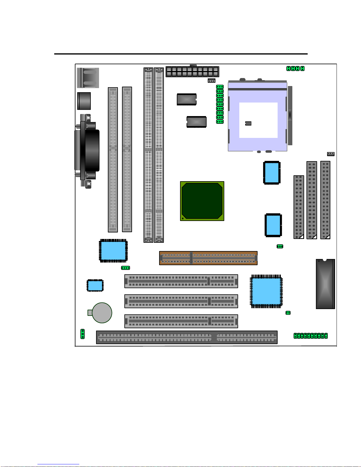
3.8 Jumper Layout Chart
SOCKET 7
SIMM1
SIMM2
ATX PWR CON.
PCI1
PCI2
AGP
FDC IDE2 IDE 1
BIOS
SMC669
64KX64
PCI3
VIA82C586B
VIA
VT82C598AT
JP2 A B C D
64KX64
LM75
TAG
32K*8
ICW48S
87-27A
LM78
CPU FAN J9
SYSTEM FAN J4
U5
U6
U8
U10
J5
DIMM1 DIMM2
JP14
ISA1
J7
J8
JP13
JP6
JP7
JP8
JP5
JP4
JP3
JP2
JP9
JP10

Viking m3 Manual P5MVP3-MATX Page 11
AWARD BIOS SETUP
4AWARD BIOS SETUP
4.1 Entering Setup
It is strongly recommended that for most applications you load the setup
defaults (as referred to in the following BIOS guide) and change only what
is necessary to configure your system. Only system administrators or
advanced computer users should configure a system on an item-by-item
basis.
Power on the computer and press the [DEL] key immediately after the memory
test is completed to enter Setup. You may also enter Setup by powering on the
system and pressing the [CTRL], [ALT] and [ESC] keys simultaneously when you
see the following message displayed briefly at the bottom of the screen:
“TO ENTER SETUP BEFORE BOOT PRESS: <CTRL-ALT-ESC> OR <DEL>
KEY”
If the message is no longer displayed before you respond then just restart your
system by turning the power off and then back on again. You may also restart
your system by pressing the [CTRL], [ALT] and [DEL] keys simultaneously.
If you are booting the system for the first time you may see the following
message:
“CHECKSUM ERROR, BIOS DEFAULTS LOADED. HIT [F1] TO CONTINUE”
This just means that the data in the BIOS Setup has been cleared and the factory
defaults loaded. You will need to go into Setup to specify custom settings for
your system.
4.2 Main Menu
Once you have entered the Award BIOS Setup Utility, the following menu will
appear on the screen. The main menu allows you to select from the various sub-
menus to specify system-specific and other customized settings for your system.
You can use the arrow keys and the [ENTER] key to navigate and enter the sub-
menus.

Viking m3 Manual P5MVP3-MATX Page 12
AWARD BIOS SETUP
Standard CMOS Setup allows you to specify pre-defined and user-defined
settings for your IDE devices in addition to floppy drive setup and entering the
time and date.
BIOS Features Setup allows you to configure functions of Award’s enhanced
features.
Chipset Features Setup allows you to configure special chipset features.
Power Management Setup allows you to configure power consumption and
power-saving features for your system.
PnP/PCI Configuration allows you to configure your IRQ, DMA and other
resource settings for your system.
Load BIOS Defaults will load the factory defaults for the BIOS.
Load Setup Defaults will load the factory defaults for the Setup Utility.
Integrated Peripherals includes configuration options for the on-board IDE
Controllers, Floppy Drive Controller, as well as Serial Port and Parallel Port
configuration.
Supervisor & User Password Setting allows you to setup up a system
password which will require a password to be entered to complete the boot
process as well as a supervisor password to restrict access to the Setup Utility.
IDE HDD Auto Detection This utility will detect and configure your IDE hard
drives and enter the information in the Standard CMOS Setup menu.
Save & Exit Setup saves all changes made in the Setup Utility and reboots the
system so the changes can take effect.
Exit Without Save will reboot the system without saving any changes made in
the Setup Utility.

Viking m3 Manual P5MVP3-MATX Page 13
AWARD BIOS SETUP
4.3 Standard CMOS Setup Menu
You can navigate through this menu by using the arrow keys. To change the
values of configurable items you can use the [PgUp]/[PgDn] or the [+]/[-] keys.
If you will refer to the image above, you will notice that the bottom section
displays various keys you can use to navigate, change values, quit or get help on
whatever item is highlighted.
User-definable items will appear in a different color from the rest of the text on
your screen. To receive help on a highlighted item, just press the [F1] key to
bring up the help menu. The memory display at the lower-right corner of the
screen is read-only for reference purposes.
DATE
To set the date, highlight the TIME field and then use the appropriate keys to
change the value of the individual sets of numbers. Available settings are:
Month: 1 to 12
Day: 1 to 31
Year: up to 2099
TIME
To set the time, highlight the TIME field and then use the appropriate keys to
change the value of the individual sets of numbers. Available settings are:
Hour: 00 to 23
Minute: 00 to 59
Second: 00 to 59

Viking m3 Manual P5MVP3-MATX Page 14
AWARD BIOS SETUP
You can also bypass the date and time prompts by creating an AUTOEXEC.BAT
file. For information on how to create this file, please refer to an MS-DOS
manual.
Hard Disk Drives
This field records the specifications for installed IDE hard drives on your system.
The onboard PCI IDE interfaces provide Primary and Secondary Channels for
installing up to four IDE devices. Each channel can support up to two IDE
devices, the first device is the “master” and the second device is the “slave” on
the same channel.
SCSI devices are configured by a dedicated controller card and are not setup in
the Award BIOS Setup Utility.
You can enter specifications for a hard drive by first selecting the type and then
either specifying a pre-defined, user or auto setting. If there is no hard drive
installed in a particular category you can choose the type “NONE” to skip the
auto-detection process for that category during boot or avoid a hard drive failure
if the drive is not currently installed.
Explanation of Spec Descriptions
The fields for specifying the hard drive type include CYLS (number of cylinders),
HEAD (number of read/write heads), PRECOMP (write pre-compensation),
LANDZ (landing zone), SECTOR (number of sectors) and MODE. The SIZE
field will automatically adjust according to the configuration you specify in the
other fields. Your hard drive’s documentation should provide you with the
information necessary to properly set up the specifications for your drive.
Auto Detection of Hard Drives on Bootup
If you decide that you want one or more of your Primary/Secondary and
Master/Slave devices to be automatically detected during bootup, you can select
“Auto” under the TYPE and MODE fields which will enable the auto detection
during bootup. This will allow you to change hard drives (with the power off)
without having to reconfigure the drives every time you switch them. If you are
using an older hard drive which does not support this function then it will be
necessary for you to reconfigure that drive every time you install it on your
system.
NOTE: Setup defaults are noted in parenthesis next to each function
necessary where they apply.
Drive A/Drive B (None)
These fields record the type of floppy drives installed on your system. The
available options for drives A and B are: 360KB 5.25”, 1.2MB 5.25”, 720KB
3.5”, 1.44MB 3.5” and None.
Video (EGA/VGA)
Set this field to the type of video display card you have installed in your system.
The options are: EGA/VGA, Mono (for Hercules or MDA), CGA 40 and CGA
80.
NOTE: If you are using a VGA or higher resolution card then choose the
“EGA/VGA” option.

Viking m3 Manual P5MVP3-MATX Page 15
AWARD BIOS SETUP
Halt On (All Errors)
This field determines which types of errors will cause the system to halt the boot
process. You can choose from the following options: All Errors, No Errors, All
but Keyboard, All but Diskette and All but Disk/Key.
4.4 BIOS Features Setup
This menu will allow you to configure the enhanced BIOS features to better
optimize your system’s performance. Some of the fields are required by the
design of the motherboard to remain in their default setting.
Virus Warning (Disabled)
Enabling this function protects the boot sector and partition table of your hard
drive against accidental modifications. Any attempt to write to them will cause
the system to halt and display a warning message. If this occurs, you can either
allow the operation to continue or use a bootable virus-free floppy disk to reboot
and investigate your system.
NOTE: Installation of new operating systems requires that this function remain
disabled until the installation is completed to prevent write errors to your hard
drive.
CPU Internal Cache (Enabled)
Enables or disables the internal cache on your processor.
External Cache (Enabled)
Enables or disables the external cache on the motherboard.
Boot Sequence (A, C, SCSI)
You can specify from a variety of options (which also include CD-ROM, ZIP Drive
and LS-120 support) to determine which device your system will look first,
second and third for the operating system to boot.

Viking m3 Manual P5MVP3-MATX Page 16
AWARD BIOS SETUP
Swap Floppy Drive (Disabled)
When enabled, the BIOS will swap the floppy drive assignments so the
drive A becomes drive B and vice versa under DOS.
Boot Up Floppy Seek (Enabled)
When enabled, the BIOS will seek floppy A drive. When disabled the BIOS will
not seek the floppy A drive.
Boot Up NumLock Status (On)
A setting of ON will turn on the NumLock light on your keyboard during bootup.
Changing the setting to OFF will leave the NumLock light off.
Memory Parity/ECC Check (Disabled)
Enabling this function will enable the DRAM Parity/ECC Check Mode for
compatible memory types.
Typematic Rate Setting (Disabled)
When enabled, you can set the two following typematic controls…
Typematic Rate [Chars/Sec] (6)
This function controls the speed at which the system will register repeated
keystrokes. Option range from 6 to 30 characters per second.
Typematic Delay [Msec] (250ms)
This function controls the time interval for displaying the first and second
characters of repeated keystrokes. You can choose from 250ms, 500ms,
750ms and 1000ms.
Security Option (Setup)
Determines when the system prompts for a password if any are selected. If you
specify “Setup”, the system will prompt for the Supervisor password only when
entering setup. Selecting “System” will cause the system to prompt you for the
password before completing the boot process. The passwords can be specified
from the Main Menu under Supervisor Password and User Password.
PS/2 Mouse Function Control (Enabled)
Enable this function when using a PS/2 mouse.
OS Select for DRAM > 64MB (Non-OS2)
When using the OS/2 operating system with more than 64MB memory installed,
you must enable this function. Otherwise leave the value set at “Non-OS2”.
Report No FDD for Win95 (NO)
Leaving this function on a “NO” setting will cause Windows 95 to report “No FDD
for Windows 95” if no floppy drive is found on your system.
Video BIOS Shadow (Enable)
Determines whether video BIOS will be copied to the system’s RAM, however, it
is optional for each video chipset design. Video BIOS shadowing will help
increase video performance.
Viking m3 Manual P5MVP3-MATX Page 17
AWARD BIOS SETUP
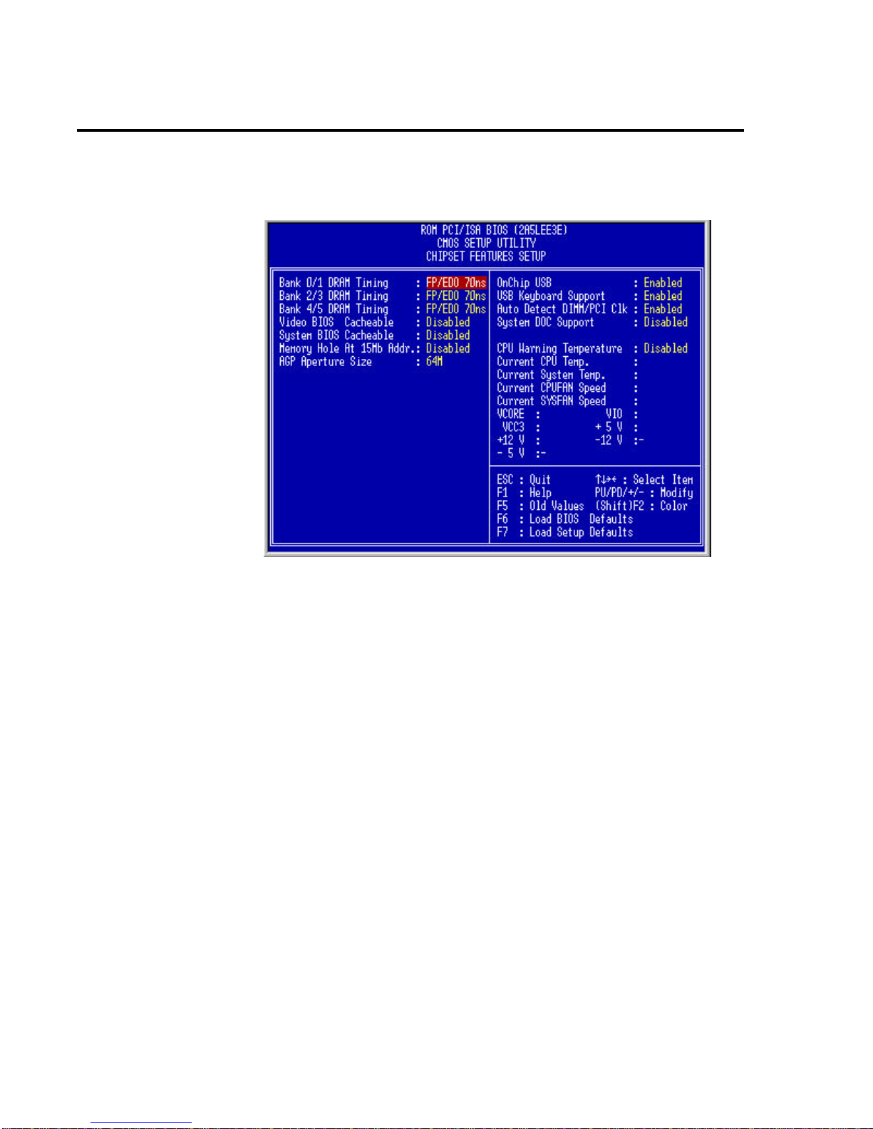
4.5 Chipset Features Setup
This menu will allow you to configure the enhanced chipset features to better
optimize your system’s performance.
Bank 0/1/2/3/4/5 DRAM Timing (FP/EDO 70ns)
Use either 60ns or 70ns settings based on what type of memory you are using. If
you are using SDRAM then you will not need to configure this option.
Video BIOS Cacheable (Disabled)
Allows the video BIOS to be cached when enabled. Enabling this function will
permit faster video BIOS execution.
System BIOS Cacheable (Disabled)
Enabling this function allows you to cache the system BIOS to help enhance
system performance.
Memory Hold at 15MB Addr (Disabled)
Enabling this function means that when the system memory is greater than
15MB, the physical memory address from 15MB to 16MB will be passed to PCI
or ISA and there will be a 1MB hole in your system memory. This option is
designed for some operating systems with special add-on cards which need the
15-16MB memory addresses.
AGP Aperture Size (64MB)
This will determine the effective size of the of the AGP Graphics Aperture which
memory-mapped graphic data structures can reside in.
On Chip USB (Enable)
Enables or disables USB support.

Viking m3 Manual P5MVP3-MATX Page 18
AWARD BIOS SETUP
USB Keyboard Support (Disabled)
Enables or disables support for USB keyboards.
Auto Detect DIMM/PCI Clk (Enabled)
When set to “Enabled”, the system will automatically turn off the PCI and DIMM
clocks which are not being used and reduce electromagnetic interference.
System DOC Support (Disabled)
When this function is enabled, the motherboard will pass the FCC Declaration of
Conformity test. This function is for compatibility testing.
CPU Warning Temperature (Disabled)
Enabling this function will allow the system to slow down when the CPU
temperature is over the warning threshold.
Current CPU/System Temperature
Monitors the processor’s temperature.
Current CPU Fan/System Fan Speed
Monitors CPU fan (FAN 2) and system fan (FAN 1) RPM.
VCORE, VIO, Vcc3, +5V, +12V, -12V
Monitors the conditions of:
Processor Core Voltage (VCORE)
Processor I/O Voltage (VIO)
Onboard 3.3 Voltage (Vcc3)
5 Volt Power Supply (+5V)
-5 Volt Power Supply (-5V)
12 Volt Power Supply (+12V)
-12 Volt Power Supply (-12V)
4.6 Power Management Setup
This menu allows you to control the motherboard’s green features.

Viking m3 Manual P5MVP3-MATX Page 19
AWARD BIOS SETUP
Power Management (User Defined)
This function allows you to set the parameters of the power-saving modes. You
can disable this if you do not want to use these features.
PM Controlled by APM (Yes)
If “Max Saving” is specified you can turn on this item to transfer power
management to APM (Advanced Power Management) which will enhance the
power-saving functions.
Video Off Option (Suspend = Off)
This function will suspend the display on your monitor when the system is
powered down.
Video Off Method (V/H SYNC+Blank)
This function will determine the method in which the monitor is put into suspend
mode. Blank screen writes blanks to the video buffer. V/H SYNC+Blank allows
the BIOS to control the VSYNC and HSYNC signals. This function applies only
for DPMS (Display Power Management Standard) monitors. The DPMS mode
uses the DPMS functions provided by the VGA card if it supports this function.
Modem Use IRQ (3)
You can set IRQs 3, 4, 5 or 7 individually through the modem. Activity detected
on the corresponding IRQ channel will “wake-up” the system.
Soft-Off by PWR-BTTN (Delay 4 Sec)
The system can be set in one of two states: one is suspend mode and the other
is Soft-Off mode. Pushing the power button for less than 4 seconds places the
system into suspend mode. When the power button is pressed for more than 4
seconds the system will enter Soft-Off mode. Setting this option to “Instant” will
shut down the system when the power button is pushed.
HDD Power Down (Disabled)
This function lets you specify the IDE hard drive idle time before the device
enters the power down state. This function operates independently from the
Standby and Suspend functions.
Doze Mode (1 Min)
Determines how much idle time is required before the system enters Doze mode.
In this mode the processor’s clock will slow down. The ratio is specified in
“Throttle Duty Cycle.” Any activity detected on the IRQ channels returns the
system to full power.
Standby Mode (1 Min)
This function determines how much idle time is required before the system enters
Standby mode. In this mode the processor will slow down and IDE hard drives
will be powered down while the monitor is placed into suspend mode. In activity
detected on the IRQ channels will return the system to full power.
Suspend Mode (1 Min)
This is another idle time requirement to place the system into Suspend mode.
Suspend mode can either suspend the system’s power or suspend IDE hard
drives. This determination is specified in “Suspend Mode Option.”
This manual suits for next models
1
Table of contents
Other EFA Motherboard manuals


