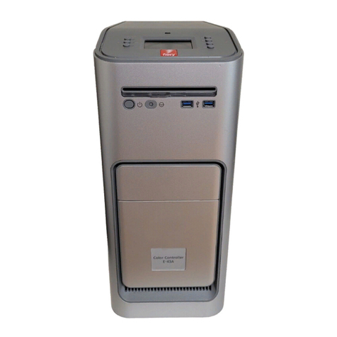
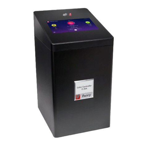
EFI Fiery X3eTY 50_45C-KM User manual

Fiery
®
X3eTY 50_45C-KM
A guide for service technicians
EFI Part Number: 45062331
14 May 2007
Service Guide

© 2007 Electronics for Imaging, Inc.
This documentation is protected by copyright, and all rights are reserved. No part of it may be reproduced or transmitted in any
form or by any means for any purpose without express prior written consent from Electronics for Imaging, Inc. (“EFI”), except
as expressly permitted herein. Information in this documentation is subject to change without notice and does not represent a
commitment on the part of EFI. The documentation is further covered by “Legal Notices” distributed with this product, which can
be found on the User Documentation CD. The documentation may be provided in conjunction with EFI Software (“Software”)
and any other EFI product described in the documentation. The Software is furnished under license and may only be used or
copied in accordance with the terms of the Software License Agreement, which can be found in the “Legal Notices” distributed
with this product.

Contents
iii
Overview
1
Precautions
2
Exploded view
5
Soft power button
6
Power up
6
Connector panel and DIAG board interface
7
Shut down and access of the Fiery X3eTY for service
7
Checking connections
12
Removing and replacing the motherboard
14
Removing and replacing components
17
Interface board 18
DIMMs 20
BIOS chip 21
Battery 22
CPU and CPU cooling assembly 23
DIAG board 27
Enclosed fan 28
Soft power button 29
Power supply 30
Hard disk drive 31
Restoring functionality after service
34
Printing Fiery X3eTY pages
35
Verifying connection to the network
37
System considerations regarding connection to the network 38
System software
39
System software installation reminders 39
Installing system software over the network port 39
Installing system software using a USB flash drive 43
Specifications
47
Hardware features 47
Networking and connectivity 47
Safety and emissions compliance 48
The troubleshooting process
49
Where problems occur 49
Before you go to the customer site 51
Preliminary on-site checkout 52
Checking connections 52
Symptoms and solutions 55
Checking the network 67
Printing to the Fiery X3eTY 67
Clearing the CMOS and power-up settings 69
Index


1
Overview
Overview
The Fiery X3eTY Color Server embeds computer connectivity and highly efficient
PostScript and PCL printing capacity into 50_45C-KM print engines. Generally, the
Fiery X3eTY does not require regular maintenance. The Fiery X3eTY is shipped with all
necessary software already installed.
Use the procedures in this guide to inspect, remove, reseat, or replace major hardware
components and to reinstall system software. Replacement parts for the Fiery X3eTY
are available from your authorized service support center.
You must reinstall system software if you replace the hard disk drive (HDD) or receive a
more recent version of the system software. You may also reinstall system software as a
way to troubleshoot the system.
F
IGURE
A
Printing system

2
Precautions
Precautions
Always observe the following general precautions when servicing the Fiery X3eTY
assembly:
1. Report any shipping damage.
If you see any evidence of shipping or handling damage to packing boxes or their
contents, save the damaged boxes and parts, call the shipper immediately to file a claim,
and notify your authorized service/support center.
2. Never alter an existing network without permission.
The Fiery X3eTY is probably connected to an existing Local Area Network (LAN) based
on Ethernet hardware. The network is the link between the customer’s computer, existing
laser printers, and other prepress equipment. Never disturb the LAN by breaking or
making a network connection, altering termination, installing or removing networking
hardware or software, or shutting down networked devices without the knowledge and
express permission of the site administrator.
3. Never assign an IP address in Network Setup.
Only the site administrator should assign an IP address on a network device. Entering an
incorrect IP address to the Fiery X3eTY can cause unpredictable errors on any or all
devices.
4. Follow standard ESD (electrostatic discharge) precautions while working on the internal
components of the print engine.
Static is always a concern when servicing electronic devices. It is highly unlikely that the
area around the print engine is static-free. Carpeting, leather-soled shoes, synthetic
clothing fibers, silks, and plastics may generate a static charge of more than 10,000 volts.
Static discharge is capable of destroying the circuits etched in silicon microchips, or
dramatically shortening their life span. By observing standard precautions, you may avoid
extra service calls and save the cost of a new board.
When possible, work on a ground-connected antistatic mat. Wear an antistatic
wristband, grounded at the same place as the antistatic mat. If that is not possible:
•Attach a grounding strap to your wrist. Attach the other end to a good ground.
• When you remove an electronic component, place it into an antistatic bag
immediately. Do not walk across a carpet or vinyl floor while carrying an unprotected
board.
• Leave new electronic components inside their antistatic bags until you are ready to
install them.
•When you unpack the electronic components, touch a metal area of the print engine to
discharge the static on your body. Place the components on a grounded antistatic
surface, component-side up.
5. Avoid flexing a printed circuit board, and handle it by opposing edges (not corners) only.
6. Never set a cup of coffee—or any liquid—on or near any components or the print device.

3
Precautions
Power Supply Cord Notice
CAUTION:
The power supply cord is used as the main disconnect device. Ensure that
the socket-outlet is located/installed near the equipment and is easily accessible.
ATTENTION :
Le cordon d’alimentation doit être débranché pour une mise hors tension totale du produit. La prise de
courant doit être située ou installée à proximité du matériel et être facilement accessible.
ATTENZIONE:
Il cavo di alimentazione deve essere scollegato per interrompere completamente la corrente. Accertarsi che
la presa di corrente si trovi o sia installata vicino alla macchina e sia facilmente accessibile.
ACHTUNG:
Der Netzstecker dient zur sicheren Trennung des Gerätes von der Stromversorgung. Stellen Sie sicher, dass
sich die Steckdose in unmittelbarer Nähe des Gerätes befindet und leicht zugänglich ist.
CUIDADO:
El cable de alimentación eléctrica se utiliza como dispositivo de desconexión principal. Asegúrese de que el enchufe-
toma esté situado/instalado cerca del equipo y que sea fácilmente accesible.
CUIDADO:
O cabo de força é usado como dispositivo principal de desconexão. Assegure-se de que a saída de energia
esteja localizada/instalada próxima ao equipamento e facilmente acessível.
VOORZICHTIG:
Het netsnoer moet worden uitgetrokken om de stroomvoorziening te onderbreken. Zorg ervoor dat het
stopcontact zich dicht bij het apparaat bevindt en gemakkelijk toegankelijk is.
Lithium Battery Notice
CAUTION:
Danger of explosion if battery is replaced with incorrect type. Replace the
battery only with the same type recommended by the manufacturer. Dispose of used
batteries according to the manufacturer’s instructions.
ATTENTION :
Il y a danger d’explosion en cas de remplacement avec le mauvais type de batterie. Remplacer uniquement
avec une batterie du même type recommandé par le constructeur. Les batteries usagées doivent être jetées conformément
aux instructions du fabricant.
ATTENZIONE:
Pericolo di esplosione se la batteria viene sostituita con un tipo non corretto. Usare esclusivamente batterie
del tipo consigliato dal produttore. Lo smaltimento delle batterie deve essere effettuato in base alle istruzioni del produttore.
ACHTUNG:
Es besteht Explosionsgefahr, wenn die Batterien durch einen falschen Batterientyp ersetzt werden. Ersetzen Sie sie
deshalb nur durch denselben, vom Hersteller empfohlenen Typ. Entsorgen Sie leere Batterien entsprechend den Anweisungen
des Herstellers.
CUIDADO
:
Existe peligro de explosión si la batería se sustituye por una de un tipo incorrecto. Sustituya la batería sólo por
una batería del mismo tipo que recomienda el fabricante. Deseche las baterías usadas según las instrucciones del fabricante.
CUIDADO:
Há perigo de explosão se a bateria for substituída por outra de tipo incorreto. Substitua apenas por outra de
mesmo tipo, recomendada pelo fabricante. Descarte as baterias usadas conforme as instruções do fabricante.
VOORZICHTIG:
Het vervangen van de batterij door een verkeerd type kan ontploffing veroorzaken. Vervang de batterij
uitsluitend door hetzelfde, door de fabrikant aanbevolen type. Het wegwerpen van batterijen dient volgens de voorschriften
van de fabrikant te gebeuren.

4
Precautions
Short Circuit Protection
WARNING:
This product relies on the building’s installation for short-circuit
(overcurrent) protection. Ensure that a fuse or circuit breaker no larger than
120 VAC, 15A U.S. (240 VAC, 10A international) is used on the phase conductors
(all current-carrying conductors).
ATTENTION :
La protection contre les courts-circuits (surtension) du produit est assurée par l’installation électrique du local où
il est installé. S’assurer qu’un fusible ou un disjoncteur inférieur ou égal à 120 V CA , 15 A aux Etats-Unis (240 V CA, 10 A
dans les autres pays) est utilisé pour les conducteurs de phase (conducteurs de courant).
AVVERTENZA:
La protezione contro i cortocircuiti (sovracorrente) del prodotto dipende dall’impianto elettrico dell’edificio
in cui è installato. Accertarsi che sui conduttori di fase (che portano la corrente) venga utilizzato un fusibile o interruttore non
superiore a 120 Vc.a., 15 A negli Stati Uniti (240 Vc.a., 10 A internazzionale).
WARNUNG:
Dieses Produkt ist darauf angewiesen, dass im Gebäude ein Kurzschluss- bzw. Überstromschutz installiert ist.
Stellen Sie sicher, dass eine Sicherung oder ein Unterbrecher von nicht mehr als 240 V Wechselstrom, 10 A (bzw. in den USA
120 V Wechselstrom, 15 A) an den Phasenleitern (allen stromführenden Leitern) verwendet wird.
ADVERTENCIA
:
Este producto depende de la instalación del edificio en lo relativo a la protección frente a cortocircuitos
(sobretensión). Asegúrese de utilizar un fusible o un interruptor de circuito que no sea de más de 120 V CA, 15A en EE.UU.
(240 V CA, 10A internacional) en los conductores de fase (todos los conductores que transportan corriente).
ADVERTÊNCIA:
Esse produto depende da instalação de proteção contra curto-circuito (sobrecarga) do edifício. Assegure-se
de que um fusível ou disjuntor de até 120 VAC, 15A U.S. (240 VAC, 10 A internacional) seja usado nos condutores de fase
(todos os condutores de corrente).
WAARSCHUWING:
Dit apparaat wordt tegen kortsluiting (overstroom) beveiligd via de elektrische installatie van het gebouw.
Zorg ervoor dat de fasegeleiders (alle stroomvoerende geleiders) beveiligd zijn met een zekering of stroomonderbreker met
een maximale capaciteit van 120 V wisselstroom, 15 A in de V.S. (240 V wisselstroom, 10 A internationaal).

5
Exploded view
Exploded view
F
IGURE
B
Fiery X3eTY exploded view
1
2a
2b
3
4
5
10
12
11
9
8
7
6
14
13
16
15
17
NOTE: For cable connector information,
see Figure H on page 12.
Key
1. Lid
2. CPU cooling assembly:
a) Clamp
b) CPU fan and heatsink
3. Interface board
4. DIMM
5. Battery
6. Fiery X3eTY motherboard
7. Fiery X3eTY power supply
8. Enclosed fan
9. HDD cable
10. HDD
11. DIAG board
12. DIAG board cable
13. Pan
14. Connector panel (see page 7)
15. Extender card
16. Rail
17. Soft power button assembly

6
Soft power button
Soft power button
The Fiery X3eTY has a Soft power button on the connector panel (see Figure C).
The green LED in the Soft power button is on when the Fiery X3eTY is powered on.
Press the Soft power button for two seconds to power on; press it for several seconds to
shut down the Fiery X3eTY. Using the Soft power button to shut down the Fiery X3eTY
does not power off the Fiery X3eTY completely.
Always shut down the Fiery X3eTY properly before you unplug the AC power cable.
Unplug the AC power cable from the wall outlet before you disconnect other cables
connected to the Fiery X3eTY. Cable disconnections require a complete power off.
Power up
In general, always make sure that the Fiery X3eTY is warmed up before you turn on the
copier. This is especially important if the system is using DHCP to assign IP addresses for
network communication and a LAN cross-over cable connects the print engine to the
COPIER port on the Fiery X3eTY.

7
Connector panel and DIAG board interface
Connector panel and DIAG board interface
F
IGURE
C
External hardware interface
Shut down and access of the Fiery X3eTY for service
The Fiery X3eTY Functions > Shut Down menu includes the following commands:
•
Restart Server
—resets the Fiery X3eTY server software without resetting the
underlying operating system.
•
Shut Down System
—shuts down the Fiery X3eTY properly so that you can safely
power off the Fiery X3eTY.
•
Reboot System
—resets both the Fiery X3eTY and the underlying operating system,
and then reboots the Fiery X3eTY.
Choose Shut Down System when you are ready to inspect and/or service the
Fiery X3eTY, according to the following procedure.
ON
12
ON
12
Service switches
Interface connector
(for image transmission)
COPIER port
(for a LAN cross-over cable)
LAN port
USB port Type A (3)
[not used]
[not used]
[not used]
Soft power button
DIAG LEDs
Normal position
Service position
Front view

8
Shut down and access of the Fiery X3eTY for service
T
O
SHUT
DOWN
THE
F
IERY
X3
E
TY
Always verify that the Fiery X3eTY is not in use before you power off or restart it. Make
sure that the system is not RIPping or printing a job. Before you take the Fiery X3eTY
off the network, always obtain permission from the network administrator.
1. Press the Utility/Counter key on the print engine.
2. Touch Controller Details.
3. At the Idle screen, press the Menu button on the control panel LCD.
4. Use the arrow buttons on the LCD to scroll and choose Shut Down from the menu.
F
IGURE
D
Menu options (2 of 3 screens)
5. At the next menu, choose Shut Down System.
6. Wait a few minutes for the green LED on the Soft power button to turn off.
Print Pages
USB Media Server
Suspend Printing
Resume Printing
Shut Down
Run Setup
Run Diagnostics
Tray Alignment
Choose this selection
to access the Shut Down
menu.

9
Shut down and access of the Fiery X3eTY for service
A
CCESSING
THE
F
IERY
X3
E
TY
To service the Fiery X3eTY hardware, shut down the Fiery X3eTY properly before you
disconnect the AC power cord from the Fiery X3eTY. Power off and unplug the
print engine before you remove the Fiery X3eTY from the print engine.
F
IGURE
E
Fiery X3eTY installed in the print engine
Print engine
(back)
COPIER port
(for a LAN cross-over cable)
Fiery X3eTY
Print engine (right side)
Interface connector
(for image transmission cable)
AC power cord
connector and
securing clamp

10
Shut down and access of the Fiery X3eTY for service
T
O
OPEN
THE
F
IERY
X3
E
TY
C
AUTION
:
Before you touch any parts inside the Fiery X3eTY, make sure that you wear an
ESD grounding wrist strap and follow all ESD safety precautions.
1. Shut down the Fiery X3eTY and the print engine (see page 8).
2. Disconnect all external cables from the connector panel of the Fiery X3eTY: the LAN port
cable to the LAN and the print engine cables (interface cable and the COPIER port
cable). If the COPIER port cable is not attached to the print engine, see page 38.
3. Disconnect the power cable from the Fiery X3eTY.
4. Remove the four screws that attach the Fiery X3eTY to the print engine.
5. Unhook and remove the Fiery X3eTY from the print engine.
F
IGURE
F
Accessing the Fiery X3eTY
Interface connector
(for image transmission)
Soft power button
Hook location
T
op screw
l
ocat
i
ons
(2)
Bottom screw locations (2)
COPIER port
for a LAN cross-over cable
LAN port
USB-A connector (1 of 3)

11
Shut down and access of the Fiery X3eTY for service
For detailed information about removing/installing the Fiery X3eTY, see the installation
instructions that accompany the print engine (not included in this service guide).
6. Place the Fiery X3eTY on a flat surface, and remove the 8 screws that secure the lid to
the pan (see Figure G).
7. Lift the lid
just enough
to reach the HDD SATA power cable (4-wire ribbon cable).
C
AUTION
:
Do not stretch, cut, or pinch the HDD cables with the lid.
8. Disconnect the SATA power cable from the HDD.
9. Disconnect the SATA data cable from the HDD.
10. Remove the lid (with the HDD attached).
Set the lid and screws aside.
F
IGURE
G
Lifting the lid off the Fiery X3eTY pan
The Fiery X3eTY is now ready for inspection and service.
Lid
Pan
Screw (1 of 8)
HDD power cable
(see Caution above)
HDD data cable
HDD

12
Checking connections
Checking connections
The most common causes of hardware problems are faulty or loose connections. Before
you decide to replace any parts of the Fiery X3eTY, make sure to verify all cables and
connections. If you have verified all external connections, check the internal connections.
F
IGURE H Cable diagram
Key to components, cabling, and
motherboard labels
NOTE: Connectors that are not
described are not used.
1. Fiery X3eTY motherboard
2. HDD, cable to SATA1
3. DIMM slots:
a) DIMM2 for standard DIMM
b) DIMM1 for optional DIMM
4. Battery in battery socket F4
5. CPU cooling assembly to FAN1
6. PCI1 for interface board extender card
7. LAN port (RJ-45 for network cable)
8. USB Type A ports (3)
9. Enclosed fan cable to motherboard
FAN3
1
2
3a
4
5
7
8
9
10
6
12
HDD
13
11a
11b
11c
13. DIAG board ribbon cable from
DIAG board J1 to motherboard J2
14. CMOS 3-pin jumper area JP1
15. RJ-45 for cross-over LAN cable
to print engine (or to PC for system
software installation)
NOT SHOWN:
Extender card
Interface board
Service switches
Default
Position
JP1
Reset
Position
JP1
10. Soft power button cables to J9 front panel
connector:
NOTE: Four wires left to right: red, black, red, yellow
11. Power supply:
a) to HDD
b) to J18
c) to J11
12. BIOS chip
SW
SW LED
J9 Front Panel
Edge of motherboard
17 18
3b
Power supply
External fan
Pan
14
15

13
Checking connections
TOCHECK INTERNAL CONNECTIONS
CAUTION:Before you touch any parts inside the print engine, make sure that you wear an
ESD grounding wrist strap and follow all ESD safety precautions.
1. Make sure that all Fiery X3eTY cables, devices, and DIMMs (dual in-line memory
modules) are present, intact, properly aligned, and well seated in their connectors.
2. Specifically check the following for proper installation in the pan: power supply, HDD,
enclosed fan, motherboard, motherboard components (see page 17).
3. Specifically check motherboard cable and component connections:
4. Specifically check all other power supply cable connections in the pan:
5. After verifying connections, if one or more Fiery X3eTY components is still not
receiving power, check the print engine and its internal interface to the Fiery X3eTY
(for information, see the documentation that accompanies the print engine).
Motherboard silk-screened label Component or cable
DIMM1; DIMM2 Socket for upgrade option; Socket for standard DIMM
U15 PLCC32 socket for BIOS chip
SATA1 HDD cable from HDD SATA data connector
FAN3 Enclosed fan with attached cable
NOTE: Airflow is out.
[on CPU, no label visible] CPU cooling assembly
FAN1 CPU cooling assembly fan with attached cable
PCI1 Extender card for interface board
J18 Power supply with attached cable
F4 Battery (see “Specifications” on page 47)
J9 Front Panel [see footnote] Soft power button with two attached cables (2 wires each):
SW LED wires are red and black
SW wires are red and yellow
NOTE: Four wires left to right: red, black, red, yellow
J11 Power supply with attached cable
J2 Ribbon cable to DIAG board at J1
JP1 CMOS 3-pin jumper area Jumper position (see page 69)
NOTE: “Front Panel” is silk-screened in two places on the motherboard. Refer only to the label that
appears at J9, on the edge of the board in very small text.
Location Component or cable
HDD Power supply with attached SATA power cable
SW
SW LED
J9 Front Panel

14
Removing and replacing the motherboard
Removing and replacing the motherboard
When the Fiery X3eTY motherboard needs to be removed and replaced, use the
following procedures. You can use a magnetic screwdriver if it is rated for electronic
components.
TOREMOVE THE FIERY X3ETY MOTHERBOARD
CAUTION:Make sure that you wear an ESD grounding wrist strap and follow standard
ESD precautions while performing this procedure.
1. If possible, print a Configuration page so that you have a record of system settings and
features (see page 35).
2. Remove the Fiery X3eTY from the print engine, (see page 10).
3. Remove the interface board according to the procedure on page 18.
4. Disconnect the following cables from the motherboard (see Figure H on page 12):
NOTE:Before you cut any tie-wraps, note the cable routing, so that you can properly
arrange the cabling later with new tie-wraps. Tie-wraps are included in the motherboard
spare kit.
•Power supply cable at motherboard J11
•Power supply cable at motherboard J18
• HDD cable at motherboard SATA1
•Enclosed fan cable at motherboard FAN3
• DIAG board ribbon cable at motherboard J2
•Soft power button cables (two) at motherboard connector labeled “Front Panel”
Four wires left to right: red, black, red, yellow
5. Remove the two screws that attach the rail to the pan. Remove the extender card from
the motherboard connector PCI1. Set aside the rail, with the extender card attached, and
the two screws.
6. Remove the screws that secure the Fiery X3eTY motherboard to the pan (four screws) and
the connector panel (four screws). Keep screws of the same type or function together.
7. Slide the motherboard away from the connector panel cutouts.
Make sure to note the position of the “metal fingers” on the USB connectors so that you
can reposition them later.
SW
SW LED
J9 Front Panel
Edge of motherboard
17 18

15
Removing and replacing the motherboard
8. Lift the motherboard out of the pan and set it on a flat, anti-static surface.
As you remove it, be careful to avoid stressing the motherboard or the surrounding cables
in the pan.
9. If you are replacing the motherboard with a new motherboard, remove the CPU and CPU
cooling assembly, DIMMs, and the BIOS chip from the old motherboard (see “Removing
and replacing components” on page 17).
TOREPLACE THE MOTHERBOARD IN THE PAN
CAUTION:Make sure that you wear an ESD grounding wrist strap and follow standard
ESD precautions while handling Fiery X3eTY components.
1. If you are installing a new motherboard:
•Transfer the CPU and CPU cooling assembly, DIMMs, and the BIOS chip.
For the proper procedures, see “Removing and replacing components” on page 17.
•Remove the battery from the new motherboard (see page 22).
Set aside the battery so that you can replace it later.
• Locate the jumper that is installed on the 3-pin jumper area JP1 on the motherboard.
JP1 is located between motherboard connectors PCI2 and PRI-IDE.
•Remove the jumper from the default position on JP1, and install it in reset position.
•Wait one full minute.
•Remove the jumper from the reset position on JP1, and reinstall it in the default
position.
2. Align the motherboard with the screw holes in the bottom of the pan, sliding the edge
connectors into the connector panel cutouts.
As you install it, be careful to avoid stressing the motherboard or the surrounding cables
in the pan. Make sure to position the metal fingers on the USB connectors.
PCI2
PRI-IDE
JP1
(default position)
PCI2
PRI-IDE
JP1
(reset position)

16
Removing and replacing the motherboard
3. Install the motherboard screws into the pan (four screws) and connector panel
(two screws).
Tighten the screws to the connector panel before you tighten the screws to the pan, to
prevent stress on motherboard connectors.
4. Connect the following cables from the motherboard (see Figure H on page 12):
•Soft power button cables (two) at connector labeled “Front Panel”
Four wires left to right: red, black, red, yellow
The two 2-wire cables are labeled SW LED and SW. SW LED wires are red and black;
SW wires are red and yellow.
• DIAG board ribbon cable at J2
•Enclosed fan cable at FAN3
• HDD cable at SATA1
•Power supply cables at J11 and J18
5. Install the extender card (with rail attached) into motherboard connector PCI1.
Align the rail onto the pan and install the two screws you removed earlier.
6. Install the interface board (see page 19).
7. Reassemble the Fiery X3eTY (see page 34) and power on the Fiery X3eTY.
8. Configure the date and time in Setup (for details, see the User Documentation CD).
9. Print a Configuration page to verify system settings and features.
SW
SW LED
J9 Front Panel
Edge of motherboard
17 18
Table of contents
Other EFI Controllers manuals
EFI
EFI E-85 Installation and maintenance instructions
EFI
EFI Fiery Quick guide
EFI
EFI E-36A Installation and maintenance instructions
EFI
EFI E-42B Quick guide
EFI
EFI E-820 User manual
EFI
EFI E-46A Installation and maintenance instructions
EFI
EFI K Performance Tiny O2 User manual
EFI
EFI E-45A Installation and maintenance instructions
EFI
EFI E-42B Installation and maintenance instructions
EFI
EFI E-42 Installation and maintenance instructions
