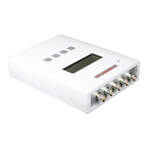
eGauge EG4 Series User manual

Quickstart Guide
Support Contact Info:
Web: KB.eGauge.net
Email: [email protected]
Phone: 877-342-8431 x2
Please visit eGauge.net/start for full
information on installing and
configuring the eGauge meter.

Before You Start...
• Read the EG4xxx Owner’s Manual.
• Install eGauge energy meters in
accordance with NEC and local codes.
• Always connect a neutral to the meter,
do not connect a ground instead of a
neutral.
• The meter requires configuration and
verification from within the eGauge
website before data is collected.
• This guide does not cover all installation
scenarios. Additional configuration is
required after install. To complete setup,
visit eGauge.net/start.
For more information and to complete software
configuration, visit eGauge.net/start
2
CAUTION/ATTENTION

3
Thank you for choosing eGauge!
To ensure that your eGauge meter is set up
to record accurate data, please complete all
required installation steps:
1. Connect Voltage (p. 4)
2. Connect Sensors (p. 7)
3. Connect Network (p. 9)
4. Software configuration & Commissioning
(p. 10)
I. Connect to the meter with a web
browser and configure the settings
II. Validate the readings
All steps must be
completed before meter
will record any data.
For detailed information related to installation
and configuration please visit eGauge.net/start

1. Determine your electrical service type.
2. Connect your eGauge “N” terminal to
the neutral bus bar of the electrical panel
using NEC compliant conductors.
3. Connect L1, L2, and L3 (if applicable) to
a 15A breaker or fuse block using NEC
compliant conductors. Ensure each line
is connected to its respective voltage
phase in the panel.
It is very important
that L1, L2, and
L3 (if applicable)
are all connected
to independent
phases. Record
which phase is
connected to which voltage terminal pin in
the table provided.
4. See the last page of this guide for
additional phasing information.
Voltage Connection
4

120/240VAC (1p/3w)
Power-off Electrical Panel!
120/208VAC (3p/4w)
eGauge L1 L2
Phase
eGauge L1 L2 L3
Phase
5

Power-off Electrical Panel!
277/480VAC (3p/4w)
For services without a neutral, or
if do not see your electrical service
here, visit the full getting started
guide at eGauge.net/start
eGauge L1 L2 L3
Phase
6

Sensor Connection
7
1. Connect current transformers (CTs) around
each conductor being measured. Depending
on the direction the CT is facing, power will
have a positive or negative polarity.
For positive values:
2. Gently squeeze the CT shut and ensure it is
latched fully (J&D CTs require 2 clicks before
closing fully).
3. Connect the 2-pin plug of the CT to a port on
the eGauge meter. Record the CT model, CT
amperage rating, phase it is on and what it is
measuring (see following page).
• eGauge ECS CTs: Point the arrow in
the same direction as the current
flow.
• J&D JSxx CTs: Point the arrow against
the direction of current flow.
• Flexible rope CTs: Point the arrow
against the direction of current
flow.

Use a table like shown below to track
the CT information, this is necessary to
configure the meter in a later step.
You may download a template at
eGauge.net/support/install-info.
8
Port CT info Item Phase
1JS16FL 100A Grid L1
2JS16FL 100A Grid L2
3JS10FL 50A Heater L1

9
Network Connection
Caution: Using grounded Ethernet plugs
(metal covered plugs) can damage the
meter or equipment if used improperly.
• Ethernet connections have a max
distance of 100 meters (328 feet).
• Check newly made CAT5/6 cables
with a network cable diagnostic tool.
• Ensure the orange and green LEDs are
illuminated on the meter Ethernet port.
• After connecting to a network source,
check for the Ethernet connectivity
symbol ( ) on the eGauge LCD
screen and that there is an IP address
under the Info screen. The connectivity
symbol will blink if it has Internet.

10
Software Configuration
After powering the meter on and connecting it
to the network, the meter can be accessed via
local IP shown on the LCD screen or by visiting
eGauge.net/find if the meter has Internet
access. Allow up to 5 minutes for the meter to
connect to the Internet.
• The username and password for the meter
is found on a label on the back-side of
the meter. This is required to configure the
meter.
• After accessing the meter, navigate
to Settings →Installation. Use the CT
information table made earlier to input the
CT information and Power Registers.
• Visit eGauge.net/start for more
information on configuring the eGauge
meter.

11
Commissioning
Before closing the electrical panel and leaving
the site, make sure to properly commission the
installation. Verify the following:
• Phasing: Verify CTs are on the correct
phases. A handheld voltmeter can be
used to check, for example, the meter’s L1
voltage terminal is the same phase as the
breaker that the CT port 1 is measuring.
See the following page for more
information on phasing.
• All CTs are facing the correct direction
and fully latched.
• Network connectivity on the eGauge LCD
screen.
• Network connectivity with a new browser
window.
• Software configuration is correct in
Settings →Installation.
• Use the Channel Checker (Tools →
Channel Checker) to verify voltage,
amperage, and power readings.

12
To measure power, the eGauge meter uses
amperage measurements collected by current
transformers (CTs) and voltage phases connected
to the line inputs. Every phase from the service
must be connected to the eGauge, as well as a
neutral. Single/split phase service requires L1 and
L2, while 3-phase service requires L1, L2, and L3.
The phase connected to the L1 line input of
the eGauge meter should be the same as the
system L1, or a “phase mix-up” may occur when
calculating power using the CT measurements
and power measurements will be incorrect.
For more information about phasing and example
diagrams, please visit
eGauge.net/support/phasing.
Phasing Information
Table of contents
Other eGauge Measuring Instrument manuals
