AUF750 Series Operation Manual OP750.1.1.7ENG
2. Starting Installation and Measurement
2.1 Inspection prior to Installation
Inspection should be made before installing the AUF-750. Check to see if the spare parts are in accordance with the
packing list. Make sure that there is no potential damage to the enclosure due to a loose screw or loose wire, which
occurred during transportation. Any questions, please contact your representative as soon as possible.
2.2 Power supply
90-260Vac, 50/60 Hz or 8-36 VDC.
2.3 Powering on
As soon as AUF-750 flowmeter is switched on, the self-diagnosis program will start to run. If any error is detected, a
corresponding error code will display on the screen (Refer to Chapter of Error Diagnoses). After that, the system will run
automatically according to the last input parameters. If the installation is accomplished when system is switched on, gain
adjustment can be monitored in Window M01. After S1, S2, S3, S4 are displayed on the upper left corner of the screen,
the system will activate the normal measurement condition automatically. It is indicated by code “*R” on the upper left
corner of the screen. The system will default to the last window settings and automatically display then at every next
power on.
2.4 Keypad Functions
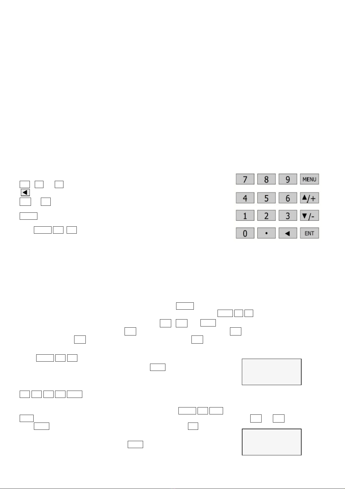
Follow these guidelines when using the AUF-750 flowmeter keypad (Refer to
Keypad Figure on the right-hand side of this page):
0 ~ 9 and . to input numbers.
to backspace or delete characters to the left.
▲/+and▼/- to return to the last menu or to open the next menu. Also acts as
“+” and “-” functions when entering numbers.
MENUto select a menu. Press this key first, input two menu numbersand then
enter the selected menu. For instance, to input a pipe outside diameter,
pressMENU 1 1 keys, where “11” is the window ID todisplay the
parameter for pipe outside diameter.
2.5 Keypad Operation
With all of the parameters entered, the instrument setup and measurement
displays are subdivided or consolidated into more than 100 independent
windows. The operator can input parameters, modify settings or display
measurement results by “visiting” a specific window. These windows are arranged by 2-digit serial numbers (including
“+” sign) from 00~99, then to +0, +1, etc. Each window serial number, or so-called window ID code, has a defined
meaning. For instance, Window M11 indicates the parameter input for pipe outside diameter, while Window F25
indicates the mounting distance between the transducers, etc.
The keypad shortcut to visit a specific window is to press the MENU key at any time, then input the 2-digit window ID
code. For instance, to input or check the pipe outside diameter, just press the ENT 1 1 keys for window ID code 11.
Another method to visit a particular window is to press ▲/+ , ▼/- and ENT keys to scroll the screen. For instance, if
the current window ID code is F66,press ▲/+ key to enter Window M65,press the ▲/+ button again to enter Window
M64; then, press the ▼/- key to back Window M65, and press the ▼/- key again to enter M66.
Example 1, To enter a pipe outside diameter of 1224, the procedure is as follows:
Press MENU 1 1 keys to enter Window M11 (the numerical value M 11
PIPE OUTER
DIAME
110 mm
displayed currently is a previous value). Now press ENT key. The
symbol “>” and the flashing cursor are displayed at the left end of the
second line on the Screen. The new value can be entered then…
1 2 2 4 ENT .
Example 2. If the pipe material is “Stainless Steel”, press keysMENU 1 4 to enter Window M14 first. Then press
ENT key to modify the options. Now, select the “1. Stainless Steel "option by pressing ▲/+ and ▼/- keys, and then
press ENT key to confirm the selection. It is possible to press the 1 key to
M 14
Pipe Material
5. pvc
change the selection and wait until “1. Stainless Steel” is displayed on the
second line of the screen. Then press the ENT key to confirm.
7