Powerdiverter CTSA16-100A Operation manual

1
Installation &
User Guide
For more information please contact CoverTel Power on 1800 (268 378)COVERTEL

2
Installation Guide
Welcome to the Powerdiverter!
Thank you for purchasing this Powerdiverter. The Powerdiverter is the most flexible, cost-effective
solar energy manager on the market, designed to save you money on your fuel bills from the day
it’s installed.
Powerdiverter works with your solar PV system to store excess solar energy in the form of heat in
a hot water storage tank or storage heaters in your home (think of them as “heat batteries”!). By
storing your solar energy, rather than exporting it, Powerdiverter saves you money every day on
your electricity bills.
Here’s how it works. Your solar panels (1) generate electricity which is converted to standard 240V
AC mains energy by the solar inverter (2). This energy is measured by your solar and supply meter
(3). If no appliances are turned on in the home to consume the energy, it gets exported out to the
grid (7). But with the addition of the Powerdiverter Sensor (4) and a Powerdiverter Controller (5), the
excess solar energy can be diverted from going out to the grid and instead stored in your hot water
tank (6) during the day for use later. Simple!
Originally launched in the UK, this new Powerdiverter has been re-designed for Australia and
New Zealand with full support for higher power water heaters up to 4.8kW and higher ambient
temperatures than we see in the UK.
The Powerdiverter offers ease and flexibility of installation. With the wireless solar power sensor
unit you can fit the Powerdiverter indoors or outdoors without drilling through walls.
With the wired sensor input on the controller, you have the option
to connect the sensor directly.
1
6
7
5 3
Figure 1
How the Powerdiverter works
4
2

3
Economy and convenience. The Powerdiverter has a special input for sensing when your controlled
load power circuit is activated by the electricity supplier for cheap rate electricity. The Powerdiverter
will then heat your water using the cheap rate electricity in addition to solar power so that you
always have hot water when you want it and at the lowest cost.
Hot water – your way! Program your own heating schedules with the 7 day 24 hour digital boost
timer to provide hot water at any time, day or night.
Need a quick boost? No worries! The boost button on the Powerdiverter gives you a quick 1, 2 or
3 hour heating boost without having to program the timer.
What’s in the box?
1 x Powerdiverter Controller unit.
1 x Powerdiverter Sensor unit (for wireless remote sensor installations only).
1 x Powerdiverter Sensor unit AC adapter.
1 x Sensor clamp with 5m cable.
1 x Wall plugs and screws kit
1 x Controller mounting template
1 x Powerdiverter installation and User Guide

4
Safety Instructions
• If using the wireless sensor unit, use only the supplied Powerdiverter AC power adaptor or 2
x 1.5V C cells.
• Use only the provided Powerdiverter Split Core CT CTSA16-100A 100A/50mA clamp.
• Please follow the installation and usage instructions carefully. If the equipment is used in a
manner not specified by the manufacturer, the protection provided by the equipment may be
impraired.
• Please note that a qualified electrician must install this product.
When fitting the current sensor clamp, follow the fitting instructions and
check the safety of the electrical cables being handled. Parts of the electrical
installation may have exposed live terminals. Consult a qualified electrician if in
doubt before installing the sensor clamp.
Do not apply the current sensor clamp around or remove from hazardous live
conductors. The sensor clamp must only be fitted to insulated cables.
Switch off the circuit before commencing installation to avoid the risk of electric
shock.
The Powerdiverter has been tested and registered on the RCM product
database.
European Conformity is a conformity marking for products sold in the European
Economic Area.
Waste Electrical and Electronic Equipment Directive is a European Community
directive that requires you to take any waste electrical and electronic equipment
to your nearest recycling facility.
Indoor use only. Unit should be installed in a location protected from weather
and moisture. See the Powerdiverter website for your stockist for more
information about suitalbe weatherproof enclosures.

5
CABLES ONLY!
INSULATED
TO BE USED WITH
CAT II
(Indelible)
Bottom Label
(Indelible)
Cable Side Label
100A/50mA
CTSA16-100A
Split Core CT
Powerdiverter

6
How to install the Powerdiverter:
To start off you will need to run through a quick checklist to ensure your home is suitable for the
installation. Please check the following:
• Do you have a grid connected solar PV system of at least 1.5kW output power?
• Is the solar inverter output connected to the same phase as the normal supply at the switch
box?
• Do you have a hot water tank with a working water heater fitted to it?
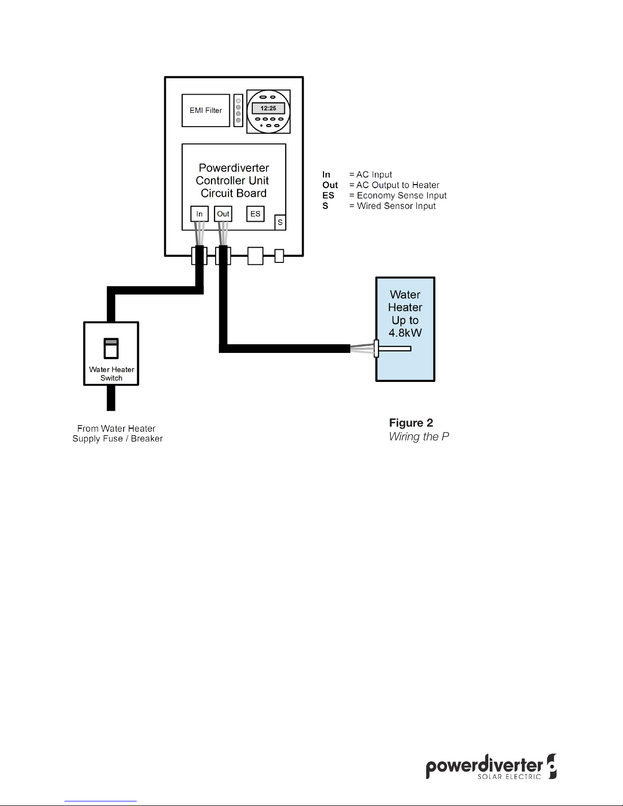
• Is your water heater rated at or below 4800W and 240V AC
• Does the water heater have a working thermostat?
• Is the water heater connected to an existing switched spur circuit? No other appliances
should be connected to it.
If the answer is yes to the all the above then you are ready to go!
Identifying Your Type of Electrical Installation
A variety of installation types exist. Please take a moment to look at the house wiring and select
the closest matching installation type. If in doubt, please contact Powerdiverter support for more
information.
There are two basic types of electrical installation:
Single Phase Supply
This is where the house has a single Active line supply of power that everything is connected
to. The solar inverter, house loads and the water heater all are fed from one Active line into the
property.
This is the easiest type of installation for the Powerdiverter to work with as the Powerdiverter
measures the net import/export power on the Active line where it leaves the property and controls
the water heater in the house fed from the same Active line. The other house loads can all share the
solar power as well.
The remainder of the installation instructions cover this type of installation.
Multi-Phase Supply
This is where the house has two or three Active line supplies.
One will be used for house loads (sockets and lights). The others will be used possibly for the water
heater, the solar inverter and/or other heavy loads (such as air conditioning or a pool heater). There
can be many variations on what is connected where in these types of installations, far too many to
cover in this guide.
The important thing to note is that the Powerdiverter Controller unit controls the active line to the
water heater and this must be on the same Active line phase as the solar inverter. The sensor
clamp (whether used directly with the Powerdiverter Controller or the wireless Sensor Unit) must
measure the net sum power of the solar generation trying to be exported to the grid, less the load
of the water heater trying to be imported from the grid ON THE SAME PHASE.

7
If the water heater is connected to a different phase to that used for the solar inverter, the
Powerdiverter will not work. You will need to move the wiring for the water heater to be on the
same phase as the solar inverter before installing the Powerdiverter.
You may wish to do this permanently by altering the house wiring to the hot water system or it can
be achieved with a Powerdiverter Controlled Load Contactor to allow both power sources to be
used.
This is useful in situations where the water heater is installed on a dedicated Controlled Load phase
for off-peak cheap electricity to heat the water. In this case, the water heater wiring is modified so
that when the Controlled Load power is turned on (by a utility meter with a dedicated Controlled
Load output or separate utility provided Load Control Unit), the Powerdiverter Controlled Load
Contactor automatically connects the water heater to that power line. When not activated, the
contactor automatically connects the water heater to the Powerdiverter Controller unit and feeds it
solar power.
See the section of the installation guide on Controlled Loads for more information or contact
Powerdiverter support for advice.

8
Step 2: Check the existing wiring between the water heater spur switch and the inside of the water
heater cap. If the wire is not 2.5mm² high temperature water heater cable, replace it. If any cable
insulation is burned or damaged in any way, replace the cable. If in ANY doubt about the safety of
the cable – replace it!
Make absolutely certain that the water heater element is working and the thermostat and the
secondary anti-boil cut out are in good condition and safe. If the water heater does not have a
secondary anti-boil cut-out, replace the thermostat with a new one that does.
Test the heating circuit with a meter that reads DC Ohms resistance and check that the heating
element reads 12 Ohms or more (for a 4.8kW, 240V AC heater element) across the Active and
Neutral terminals where the cable from the Powerdiverter connects. If it reads lower than 11.5
Ohms, check the power rating of the heating element and check the wiring for short circuits. If
it reads more than 25 Ohms, check the heating element, thermostat and secondary cut-out (if
present).
Tip: If you do not have a test meter, a quick check is provided by the Powerdiverter LEDs. When
the heating circuit is being fed power but the circuit is open, the ‘Knight Rider’ display shows on
the red LEDs. This normally means the water is hot but could mean the thermostat or heater or
wiring is faulty if the water is cold.
Step 1: Ensure the power has been isolated to the water heater feed circuit at the consumer unit
(and/or turn off the water heater spur switch).
Figure 2
Wiring the Powerdiverter

9
Figure 3
Checking existing wiring
Figure 3 shows a classic example of burned out wiring from a faulty thermostat on an old water
heater. In this case the wiring and the thermostat had to be replaced before fitting the Powerdiverter.
Step 3: Open the Powerdiverter controller unit to see the connections. Install the supplied cable
glands into the pre-cut holes. If the existing cabling is long enough to reach into the Powerdiverter
and back out to the heater and is in good condition, you can simply cut the cable between the spur
switch and the immersion heater and re-use it in step 5.
Step 4: The unit should always be sited out of direct sunshine or places that are likely to reach
more than 40 degrees Celsius to avoid the unit becoming too warm and reducing its output power.
If installed outdoors, the unit should be installed in a weatherproof enclosure with ventilation to
allow cooling air to circulate around the Powerdiverter.
The unit should ALWAYS be installed in a vertical position
to allow cooling air to circulate from the bottom to the top
vents on the Powerdiverter enclosure.
Please ensure there is at least 10cm of clear space from
the top and bottom and 5cm of clear space to each side of
the Powerdiverter control unit for air circulation.
If the unit is installed in an airing cupboard do not cover the
unit with anything or allow items of clothing to block the air
vents as the unit may become too warm and shut down to
protect itself.
Fit the controller unit to the wall using the four screw holes
provided in the enclosure corners. Use the wall plugs and
screws provided or ones suitable to the type of wall. Check
for cables and pipes in the wall before drilling or screwing
into the wall!
A cardboard drilling template has been provided to make
this easier.
KEY BENEFITS:
HOT WATER FROM SOLAR PV
Powerdiverter has dual inputs allowing you to connect your on/o-peak
tari supplies ensuring hot water security at the lowest possible rates.
The powerdiverter uses custom-designed wireless technology to make this product the
easiest to install in Australia. Years of experience within the solar PV industry has been key to
the design and functionality of the powerdiverter to maximise your return on investment.
Built for Australia
Save up to $650 extra on
your annual energy bills
24/7 timer for scheduled hot
water boosting or use the
Easy Boost button for hot
water on demand
Powerdiverter automatically
knows when to boost to
protect against legionella.
Can be installed within
minutes with the wireless
battery or mains sensor unit
Extendable 5 year warranty
Variable power control that
delivers spare energy in all
weather conditions
No plumbing or additional
wiring required
Use up to 100% of the excess
power being generated
Hot water from your excess
solar electricity using your
existing hot water heater.
Compatible with all
hot water elements
up to 4.8kW
www.powerdiverter.com.au
+61 (0) 413 150 000
sales@powerdiverter.com.au
5cm
10cm
5cm
10cm
5cm 5cm
10cm 10cm
Figure 4
Installation locations and position

10
Step 5: Connect the power cable from the spur switch to the AC input connector on the left hand
side of the circuit board, following the Live (Active), Neutral and Earth markings. Solid core or
stranded cables up to 6mm² can be used. To open the connector, lift up the white levers. Strip 1cm
of insulation from the wires, twist the strands together and insert the bare wire end into the hole.
Flip down the lever.
Figure 6
Economy Sense
Step 6: Connect the water heater cable to the middle connector block on the circuit board in the
same way as in step 5 above.
Economy Sensor Connector
If required, connect a feed from the controlled load circuit to the right hand connector block.
Figure 5
Before wiring and after wired
Please consult your energy supplier to determine if your “normal” supply is also charged at a lower
rate during these times as this depends on the type of supply meter(s) fitted at your property.
This optional connection is for sensing the presence of power on the economy / cheap rate circuits
controlled by the electricity supplier.

11
When AC power is applied to this connector, the Powerdiverter assumes that it is from a
controlled load circuit that tells it that the electricity supply is in a cheap rate period. This will trigger
the Powerdiverter to apply full power to the heater from the normal power circuit feeding the
Powerdiverter.
The economy rate sensor input does not require heavy gauge cable, as it draws a maximum of 1.5
watts of power. It does not require an earth connection but one is provided in case a 3 core cable
is used. Any cable of 1.5mm² or greater can be used, if appropriately fused at the source.
Fitting the Sensor
You have two choices for fitting the sensor:
You can use either a wired sensor clamp, which plugs into the controller or a wireless sensor unit
that can be installed remotely.
To use the wired sensor clamp, the controller unit must be located close to the place where the
sensor clamp needs to be installed (a cable where the supply comes into the property) and close to
the wiring for the heater. The supplied sensor clamp has 5 meters of cable.
To use the wireless sensor, you need the wireless sensor unit and the plug-in sensor clamp. The
sensor unit can be powered by batteries or an AC adaptor, which will need a socket to be located
near to the sensor unit. If not using the batteries to power the unit, please remove them to prevent
eventual leakage.
To use the wireless sensor outdoors, make sure that the sensor unit and AC adaptor are installed in
a weatherproof box. See your Powerdiverter supplier for an all-weather enclosure.

12
Step 7: With either setup, fit the sensor clamp to the active incoming supply cable tail. The arrow
embossed on the top of the sensor clamp should point towards the switch box/load. This sensor
clamp must be located before the solar inverter circuit. If the inverter is installed via a service
connection block, be sure to install the Powerdiverter sensor clamp before the block so that it
measures the sum of the generation and load.
See Figure 7 and 8 for more details on where to install the sensor clamp. Follow these instructions
carefully as the Powerdiverter will not work properly if the sensor clamp is installed in the wrong
place or the wrong way round.
Figure 7
Sensor clamp
Figure 8
Installing the sensor clamp
Switch Box
Service
Connection
Block
Supply
Meter
1234
Active
Line
Solar PV
System
Supply Fuse
Installation position for Powerdiverter
sensor clamp on Active wire (brown).
Note the direction of the arrows on the
sensor clamp!
OR

13
Step 8: For wireless sensor installations
Plug the 3.5mm jack from the sensor clamp or extension cable into the Powerdiverter sensor unit. If
using the extension cable, plug the sensor clamp into the end of the extension cable.
If you are using the AC adapter, remove the batteries from the unit (to avoid leakage), and plug
the AC adaptor into a mains power socket. Plug the AC adaptor’s DC power plug into the
Powerdiverter sensor unit. Switch on the AC adaptor at the wall socket.
Note for houses with 2 or 3 phase power: Make sure the mains adaptor is plugged into a socket
that is on the same phase as the Powerdiverter controller unit and the solar system. If it is plugged
into a socket on a different phase, the Powerdiverter will not function correctly.
If using the batteries, open the hatch on the sensor unit and install two C-sized battery cells.
Once activated, the LED on the sensor unit should blink
red and then green once as a test and then blink orange
for 2 minutes.
In the Powerdiverter controller unit, set the jumper on
J3 “Sensor Select” to be on pins 2 and 3 for “Wireless”
sensor operation.
Step 8: For wired sensor installations
Route the sensor wire to the Powerdiverter controller unit
and feed the 3.5mm jack plug from the sensor clamp
through the 16mm gland on the Powerdiverter controller
box.
Plug it into the sensor socket on the Powerdiverter
controller circuit board. Set the jumper on J3 “Sensor
Select” to be on pins 1 and 2 for “Wired” sensor
operation.
Figure 9
J3 Wired sensor selection
Step 9: Once you are happy with the wiring installation of the controller unit, please fit the front of
the unit back on, using the four captive screws built into it. The holes in the front face should be
matched up to the LEDs and the timer clock and then the front face can be pushed home on to the
seal.
You are now ready to test the system!
Switch on the spur switch next to the water tank and you will see the LEDs on the Powerdiverter
controller unit blink twice as a self-test. Depending on whether you have installled using a wired or
wireless sensor, follow the instructions in the following relevant sections.

14
Testing For Wireless Sensor Installations
Make sure that the wireless sensor unit is turned on at the mains or has the baterries installed so
that it is transmitting.
After two minutes, the green LED on the Powerdiverter controller unit will then start to flash every 2
seconds (showing that the sensor unit is communicating to the controller unit).
When first installed, each Powerdiverter is pre-set at the factory to a unique communication pairing
code. For all normal installations, the system is ‘plug and play’ and it should not be necessary to
pair the units. If you experience difficulty with getting a signal from the sensor unit to the controller
unit, please look at the suggestions in Appendix A to see if these can solve any problems.
If you need to re-pair the units for any reason, see Appendix B for details on how to do this.
Testing the Installation – “The Kettle Test”
It is very important to test the installation before leaving it to work. The sensor clamp must be
installed in the correct place in the wiring and the correct way round in order to correctly detect
exported solar energy. If not installed properly, the system can work “backwards”, resulting in
energy being diverted at the wrong times.
The easiest way to test the installation is with a “Kettle Test”.
1. Turn off the solar inverter. This allows us to be sure that the house is importing energy.
2. Turn on a large load (such as a kettle filled with cold water). The LED on the Powerdiverter
sensor unit should blink red every 2 seconds (AC powered) or 6 seconds (battery powered)
to show that energy is being imported from the grid to run the load. All the red LEDs on the
controller unit should be out or rapidly turn off if any were on. If the sensor LED blinks green in
this step, check the position and direction of the sensor clamp.
3. Turn off the kettle and turn on the solar inverter. After a couple of minutes the inverter will start
up and commence generating if it is sunny. At this time, the LED on the Powerdiverter sensor
unit should start to blink green if there is excess solar power being exported from the house. If
there is enough excess solar power, one or more of the red LEDs on the controller will start to
light up to show that diversion has started.
Note: Do not install the sensor clamp on the power line to the solar inverter itself. If a
service connection block is used to connect the solar inverter circuit, make sure the
clamp is installed on the supply side of the block, closest to the supply meter.

15
Testing For Wired Sensor Installations
When turning on the Powerdiverter controller in wired sensor mode, the usual LED test will show
and then after a few seconds the green LED will blink every 2 seconds when there is no excess
solar power detected or the house is consuming energy from the grid. This also serves to show
that the Powerdiverter is switched on.
The Powerdiverter controller cannot be used simultaneously with a wired and wireless sensor. If
J3 is set to “Wireless” operation, the wired sensor will be ignored. Similarly, if J3 is set to “Wired”
operation, the wireless sensor will be ignored.
Testing the Installation – “The Kettle Test”
It is very important to test the installation before leaving it to work. The sensor clamp must be
installed in the correct place in the wiring and the correct way round in order to correctly detect
exported solar energy. If not installed properly, the system can work “backwards”, resulting in
energy being diverted at the wrong times.
The easiest way to test the installation is with a “Kettle Test”.
1. Turn off the solar inverter. This allows us to be sure that the house is importing energy.
2. Turn on a large load (such as a kettle filled with cold water). The green LED on the
Powerdiverter controller unit should blink every 2 seconds to show that energy is being
imported from the grid to run the load. All the red LEDs on the controller unit should be out or
rapidly turn off if any were on. If the green LED lights solidly in this step, check the position and
direction of the sensor clamp.
3. Turn off the kettle and turn on the solar inverter. After a couple of minutes the inverter will start
up and commence generating if it is sunny. At this time, the green LED on the Powerdiverter
controller unit should light solidly if there is excess solar power being exported from the house.
If there is enough excess solar power, one or more of the red LEDs on the controller will start
to light up to show that diversion has started.
Note: Do not install the sensor clamp on the power line to the solar inverter itself. If a
service connection block is used to connect the solar inverter circuit, make sure the
clamp is installed on the supply side of the block, closest to the supply meter.

16
Note on Water Heater Thermostat Wiring and Setting
It is very important that the water heater has a working thermostat and that it is wired into the
Active (brown wire) feed from the Powerdiverter. Without this, the water in the tank can boil,
resulting in damage to the tank and/or serious personal injury from the excessively hot water.
Adjust the thermostat to a temperature higher than 60°C so that bacteria cannot grow in the tank.
Check the instructions from your water heater for details on how to do this.
Adjust any external tank thermostat for a gas/oil boiler similarly. Best effectiveness of the
Powerdiverter is obtained by setting the water heater thermostat to a higher temperature than the
boiler thermostat. This allows the Powerdiverter to heat the water to a temperature that prevents
any external boiler from turning on, which saves wasted fuel.
A typical water heater with thermostat correctly wired is shown in Figure 10. Be sure to replace and
secure the insulated water heater cap when wiring is completed. Note that this thermostat has an
integral anti-boil cut-out switch. If this is triggered or the thermostat is new, you may need to press
the reset button on the thermostat body to allow the heater to work.
Figure 10
Setting the thermostat temperature and anti-boil cut-out

17
Installations With Controlled Load Circuits for Water Heating
The Powerdiverter needs to be connected to the normal day circuit phase where your solar inverter
is connected in order to receive solar power during the day. The output of the Powerdiverter needs
to be connected to the heater element directly and no other appliances.
Depending on your type of electrical installation and local electrical regulations, you may have a
dedicated hot water circuit and meter that supplies cheap rate electricity to your hot water tank
heater. This is known as a Controlled Load circuit and is controlled by your utility company through
the meter by remote control (ripple frequency control) or a built in timer switch programmed by your
utility company for off peak times of the day or night.
For single phase supplies, you may have a “E2” type of utility supply meter which has a separate
cheap rate meter output or your utility company may have fitted a separate Load Control Unit (LCU)
which receives power all the time from the meter but which has the ripple frequency receiver or
timer unit in it to turn on/off the line to the water heater.
Some single phase installations may switch the whole house to use cheap rate electricity while
others may only allow the Controlled Load circuit to receive cheap rate electricity with the rest of
the house always receiving full rate electricity.
In using a hot water storage tank with a Powerdiverter, you have a few choices of how to deal with
the Controlled Load circuit.
Permanent Wiring of Water Heater to Normal Circuit
You may choose to permanently rewire the water heater to use the solar output of the
Powerdiverter, disconnecting it from the Controlled Load circuit.
Note: Some utility companies may require you to change tariffs and/or remove or change your
Controlled Load meter or LCU if you chose to permanently disconnect the water heater from the
Controlled Load circuit. Please consult your utility company for advice.
Use of Economy Sense Input for Homes with Whole House Off Peak Electricity
If all the house circuits also receive cheap rate electricity, you can connect the Controlled Load
circuit to the Economy Sense input on the Powerdiverter so that the Powerdiverter knows when
the electricity is cheap and automatically boosts the water temperature (overriding the solar or timer
functions). This is shown in Figure 11 (over the page). If you do not wish to have the water heater
run when cheap rate electricity is available, turn off the Controlled Load main switch (MCB/RCBO)
to the Powerdiverter.
No Cheap Rate Power Use
Even if cheap rate electricity is not provided to the whole house normal supply, the benefit of solar
power to heat the water will most likely out-weigh the cost of sometimes running the water heater
on “normal” full rate electric, rather than the cheap rate dedicated supply.
In this case, do not connect the Economy Sense input to anything and use the manual boost
button or the programmable timer built into the Powerdiverter Controller unit to run the water heater
as required, in addition to the automatic solar power use.
Other Uses of the Economy Sense Input
The economy rate sensor circuit can be used to cause the Powerdiverter to boost to the heater by
applying 240V AC to the terminals and may be used for other purposes such as remote wireless
boosting, for example. Please contact Powerdiveter support for more information.

18
Figure 11
Connecting to Controlled Load Power and Normal Power Lines
By using an optional Powerdiverter Controlled Load Contactor, the water heater may be connected
to both the Controlled Load power line and the output of the Powerdiverter Controller at the same
time.
The wiring diagram in Figure 12 opposite shows how the Powerdiverter Controlled Load Contactor
works and should be connected.
This is especially useful for installations where you wish to use the cheap rate electricity supplied by
the Controlled Load power line from your utility meter or LCU and the utility company requires that
the water heater load be permanently connected to that supply line.
The Powerdiverter Controlled Load Contactor is a special DIN rail contactor switch which has its
activation coil connected to the Controlled Load Active / Live line.
The contactor has a Normally Closed position that is selected automatically by a spring when there
is no power applied to the Controlled Load line. This allows the water heater to be connected
to the Powerdiverter Controller and receive solar power (or manual boost power or timed boost
power) from the Normal day circuit. This electricity is either “free” solar power or Normal rate
power.

19
Figure 12
Help and Support
For more help with installing or using the Powerdiverter, please check out the support pages with
our “how to” videos on our web site at:
www.powerdiverter.com.au
Water
Heater
Common Neutral
NO
Controlled Load Live
Powerdiverter
Controlled Load Contactor
NC
Coil
1234
Powerdiverter
Controller
Normal Live
Note: For clarity, the
Earth connections are not
shown in this diagram.
When the utility company activates the Controlled Load (either by the LCU or meter), the
Powerdiverter Controlled Load Contactor coil is energised and immediately and automatically
switches the water heater to be connected to the Controlled Load circuit via the Normally Open
contacts for as long as it is energised by the utility company.
In this way the water heater is effectively “permanently connected” to the water heater as it is
automatically connected to the Load Controlled circuit whenever it is actually supplying power.
Anti-bacterial Timer
In any event, the automatic anti-bacterial water heating function will operate whenever the
Powerdiverter is turned on and senses that the water heater has not reached the set thermostat
temperature in at least once in every 7 days of operation.

20
User Operation Guide
Sensor Unit Indications
The Powerdiverter sensor unit has a single LED that blinks to let you know that it is transmitting
data and whether the house is importing or exporting energy.
The sensor unit LED will blink every two seconds when mains powered and every six seconds
when battery powered.
The LED blinks red when the house is importing grid energy and it blinks green when the house is
exporting energy.
In time with the sensor unit LED, the green LED on the Powerdiverter controller should blink to
confirm communication. If it does not, either move the sensor unit to a different location or try re-
pairing the transmitter and controller units, as detailed earlier.
When powered by batteries, the sensor unit will also indicate if it is out of radio range. If it is out of
range, it blinks the LED in a ‘green-red, green-red’ pattern every 6 seconds.
Note: During the first two minutes of operation, the LED blinks orange every 2 seconds to
show that it is possible to re-pair the radios. During this time, the Powerdiverter will not
divert energy and Easy Boost mode cannot be started.
Powerdiverter Controller Operation
The Powerdiverter is normally completely automatic when working from solar or wind power.
It constantly measures the power available to export to the grid and when there is more than the
minimum excess power available, it starts to gradually feed power to your water heater. When the
sensor unit is AC powered, the Powerdiverter starts diverting power when there is more than 50W
power available. When the sensor unit is battery powered, the Powerdiverter starts diverting power
when there is more than 100W power available.
The three red LEDs on the controller unit indicate the level of power being diverted to the water
heater, with one LED meaning that the Powerdiverter has started to feed energy to the heater,
two meaning that over half power is applied, and all three red LEDs meaning that full power to the
heater is applied.
When the water is fully hot, the thermostat on the heater will click open to stop heating. The
Powerdiverter recognizes this and signals that the water is hot by showing the three red LEDs
running up and down on the controller (like the red lights on the car in ‘Knight Rider’, if you
remember that 1980’s classic TV series!).
To turn off the Powerdiverter, simply use the existing wall mounted water heater spur switch.
Table of contents
Other Powerdiverter Inverter manuals