EHC EH500.38.63 User manual

The Combination Range of
Electric Radiators
The Electric Heating Company Limited
Unit 40 ,Block 5, Third Road,
Blantyre Industrial Estate,
Glasgow
G72 OUP
Tel:01698 820533
info@electric-heatingcompany.co.uk www.electric-heatingcompany.co.uk
the electric heating company
INSTALLATION
&
OPERATING INSTRUCTIONS
THESE INSTRUCTIONS SHOULD BE READ CAREFULLY AND RETAINED
FOR FUTURE REFERENCE.
BE SURE TO OBSERVE ALL LABELS AND WARNINGS ON THE
APPLIANCE.
Fax: 01698 820533

CONTENTS
1.
Safety information ...................................4
2.
General information ..................................2
3. Installation .........................................5
4. Operating instructions ...............................10
5. Operating safety .................................. 10
6. Technical data .....................................13
7. Control Types......................................14
This appliance is not intended for use by persons (including children) with reduced physical, sensory
or mental capabilities, or lack of experience and knowledge, unless they have been given supervision
or instruction concerning use of the appliance by a person responsible for their safety. Young children
should be supervised to ensure that they do not play with the appliance;
Electrical Connections
IMPORTANT
The wires in the mains leads are coloured in accordance with the following code:
GREEN & YELLOW: EARTH
BLUE: NEUTRAL
BROWN: LIVE
WARNING – THIS APPLIANCE MUST BE EARTHED
The installation of this appliance should be carried out by a competent electrician in
accordance with I.E.E. Regulations for Electrical Equipment.
The radiator is fitted with a standard UK 3 pin plug that can be directly connected to an
electrical socket. Care must be taken when connecting radiators in this way not to overload the
ring main circuit. If you are unsure contact a qualified electrician.
Alternatively, the mains cable can be cut to length by a Qualified Electrician and connected to
a suitable 13A DP Switched Fuse Connection unit adjacent to the radiator. This connection unit
should comply with BS 1364-4 having a contact separation of at least 3mm. Please ensure that
the electricity supply is disconnected prior to using this installation method.
Page
Page 1

1.General Information
EHC Combination Electric radiators have been designed using the latest technology to create an
elegant solution for all hard to heat situations. They can be installed in almost any location apart from
the safety restrictions noted in this manual.
The range has been developed to provide a flexible solution for electric heating in Domestic properties,
Conservatories, Holiday homes, Offices and any temporary heating situation.
Our unique patented ’Magmatic’ heating tablets provide the heat source for your new radiator. Whilst
the radiator is classed as a 100% efficient Direct Acting appliance, the heating tablets provide partial
storage to prolong your heating comfort and to reduce running costs. The radiator has a robust body
which incorporates a spot welded high fin surface area to ensure that there are no contraction noises
during the heating cycle. The high fin design boasts 6 times the normal radiator surface area to provide
a balance of Convection and Radiant heat for your added comfort.
The radiators can be simply plugged in to a Standard socket or Hard wired to an existing
spur connection. The range has the flexibility of being Wall mounted or free standing on Castors or
Feet.
For added versatility we can supply Conservatory radiators which are also ideal for use below windows
with low sills.
Control types:
All our standard model sizes are supplied with a TEI 1 manual room thermostat. For a fully controllable
central heating system, the radiators can be installed with our EHC Control Box, Single or twin Zone
Programmer's and Room Thermostatsto comply with the latest Building Regulations.
In addition to the above we also supply Radio Frequency controlled radiators which provide all the
benefits of the standard version however the control wiring is eliminated. These models can be
controlled by our T-Pod and T-Basic Programmers.
Also available is our TDI range of Electric Radiators. Simply plug in the radiator to a standard 13amp
socket and control by TIME & TEMPERATURE using the TDI control located within the side of the
radiator.
WiFi Control:
DSR WiFi Control is our easy to use App based control system. To take benefit of this feature you
simply need to purchase and connect the radiators to our DSR Wifi Gateway.
The DSR WiFi App gives you total control of all your heaters independently or in groups should you
choose. The system can be controlled from a computer,smart phone or tablet using our Free App.
Additionally, adding an optional Power Meter to the system will give you further controllability over the
total available power within your home. The Power Meter constantly monitors the whole house electrical
demand. If the set demand is ever reached the system will temporarily disable your chosen heaters until
the demand is reduced where they will be reactivated automatically.
All EHC radiators are manufactured to the highest safety and quality Standards. Each radiator is CE
Marked and carries all the necessary European Approvals. Each radiator is fully checked and
tested prior to leaving the factory and as such is packed with full Quality certification.
We hope you enjoy the comfort provided by this superior product and we look forward to being of
assistance to you in the future.
Page 2

2.Safety Information
Handling
This radiator is very heavy. Take adequate precautions when lifting and manoeuvring it. Always
assess the load, and seek assistance with heavy or awkward loads that are beyond your
capabilities.
Positioning
This radiator is very heavy. In order to maintain stability and to ensure its future safety in use,
it is essential that the radiator is FIXED SOUNDLY TO A WALL and that the brackets are
mounted on a FIRM, LEVEL SURFACE. Castors or Feet can be purchased as an accessory.
Care should be taken to avoid irregular surfaces.
It is important that the following instructions are strictly followed.
Keep the following minimum safety distances to avoid fire risk due to high surface
temperatures of the appliance during heating cycles:
Lateral heating walls – masonry ........................................................ 50 mm
Lateral heating walls – combustible matter...................................... 100 mm
Heating walls above floor ................................................................... 80 mm
Cover plate – combustible covering installed on top of it ................ 150 mm
Cover plate – non-combustible covering installed on top of it ......... 100 mm
Please note that our IPX4 rated models should be used in bathrooms.
Portable radiators must not be fitted in bathrooms or wet areas.
CAUTION – This radiator must not be located below or in front of a fixed socket outlet.
DO NOT POSITION under windows where curtains may contact the radiator.
DO NOT PLACE THE APPLIANCE in the vicinity of a swimming pool.
Installation
It is important that the fixing device chosen is appropriate to the wall material to which the
radiator is being fixed. Some modern internal building materials are very low density block
and require specialised fixing devices to provide a safe, secure installation.
Ongoing safety
CAUTION – If during any reassembly of the radiator, a part of the thermal insulation shows
damage or deterioration which may impair safety, it should be replaced with an identical part.
CAUTION – In order to avoid overheating, do not cover the radiator.
DO NOT COVER OR OBSTRUCT the surfaces of the appliance.
DO NOT PLACE OBJECTS in contact with the radiator.
Page 3

3. Installation
Preparation
1. Before beginning, remove the radiator and parts from
the box and check everything is present and correct.
In addition to the radiator body, there should be a top
grille, a pair of mounting brackets, four suspension
hooks, a set of mounting screws & plugs and an
instruction manual.
20 cm 37 cm 50 cm 67 cm
80 cm 110cm 140 cm
Rad. Length(cm)
38
55
68
85
98
128
158
Bracketseparation(cm)
20
37
50
67
80
110
140
Page 4
Note: Setting the brackets to the Minimum recommended 18cm to the lower fixing point will leave a
distance of approx 8.7cm from the floor to the bottom of the heater
38 55 68 85
98128 158

3. Installation (cont.)
Wall fixture and fittings
2. Drill, plug, and secure the brackets to the wall. Appropriate fixtures must be used depending
on the wall material:
Solid brick/High density block walls
These must be drilled and plugged with the Rawlplug No. 10 size fibre inserts provided. The
correct size of drill (5.5mm) should be used and the hole should be drilled to a depth of
8mm greater than the length of the Rawlplug so that the fixing is made below the plaster
layer.
Low density block walls
A special fixing, such as Unifix LB70 should be employed, (following fixing instructions).
Panelled internal walls
It is preferable to locate the studding and use the No.10 size wood screws provided. Where
it is not possible to locate the studding use Hollow wall anchors and securely fasten the
brackets to the plasterboard when this method is used we recommend that radiator feet are
used to take the full weight of the radiator. For other wall materials the wall panel
manufacturer should be consulted for details of suitable wall fixing devices.
Note: Radiators will be set to an approximate height of 185mm from the floor when support
feet are used.
3. Fit two Small suspension hooks into the bottom slots in the brackets, and hang the bottom
of the radiator on them. Make sure the radiator is sitting right back on the hooks and not just
resting on the fins.
4. Fit the other two Large suspension hooks in
the top slots of the brackets, and lift them up.
Push the radiator back against the wall and
drop the suspension hooks back down to lock it
in position.
5. The top grille of the radiator can then be fitted
and secured with the securing screws at each
end.
Page 5

3. Installation (cont.)
6. At the bottom of the radiator, next to the mains
connection there is a small temperature sensor.
Loosen the gland and pull the sensor down by
approx 5 cm, then re-tighten the gland. This
enables the radiator to gauge the room’s
temperature.
Electrical installation
•The appliance has been designed to be connected to 230 V (nominal) alternating current (AC);
50Hz supply and comes with a standard UK 13A 3 pin plug that can be directly connected to an
electrical socket.
•All electrical installation work, in particular protective measures, must be carried out in
compliance with the BS7671 regulations, statutory provisions and ‘best industry practice’ of the
respective utilities provider.
•The electrical installation may only be carried out in compliance with the installation instructions
and by a competent suitably qualified electrical engineer.
WARNING - THIS APPLIANCE MUST BE EARTHED
•For each supply, a means for disconnection must be incorporated in the fixed wiring by a
double pole switch with a contact separation of a minimum of 3mm and in accordance with the
current IEE Wiring Regulations.
•The heater must not be installed immediately below a fixed socket outlet or any combustible
object.
•If multiple heaters are to be installed and plugged into the domestic socket ring circuit then
considerations should be made in regards to the total circuit loading.
Note:
Only IPX4 radiators are suitable for installation in bathrooms which allows for the
heater to be installed within Zone 2 as per regulation 701.32.4. Regulation 701.411.3.3 of
BS7671 means that all circuits within a location containing a bath or shower will require RCD
protection not exceeding 30 mA and have the characteristics specified in regulation 415.1.
Local isolation should be provided for the heater however the isolation device must be installed
out with all zones and in compliance with regulation 701.512.3 and Section 53 of BS7671.
‘Bathroom Zones for Radiator installation’ Zone 2
Zones
Page 6

L
4
1
2
A1
A2
3A
Radiator
Radiator
Radiator
3. Installation (Single Zone Wiring)
Control wiring to be
1.5mm Twin & Earth
cable.
Radiator wiring should be a minimum
of 2.5mm Twin & Earth cable.
Page 7
7.

ZONE 1
RADIATOR
ZONE 1
RADIATOR
ZONE 2
RADIATOR
ZONE 2
RADIATOR
L
3
4
A1 A1
A2 A2
1 1
2 2
3. Installation (Twin Zone Wiring)
3A
Control wiring to be
1.5mm Twin & Earth
cable.
Radiator wiring should be a minimum
of 2.5mm Twin & Earth cable.
Page 8
8.

3. Installation (cont.)
Control cabling – RF models
All Radio Frequency radiators come complete with a pre-wired receiver in T-RF which is
controlled by either the T-Pod or T Basic Thermostat.
9.T-Pod installations
a
b
Follow the instructions outlined in section 7for single radiator installations.
Locate the T-Pod programmer on a suitable wall in the same room as the radiator.
Configure the T-Pod programmer and receiver in T-RF located on the radiator.
According to the instructions included in the T-Pod packaging. Set the required
program times and temperatures.
10. T-Basic installations
a
b
c
d
Follow the instructions outlined in section 7for single radiator installations.
Locate the T-Basic digital room thermostat on a suitable wall in the same room as
the radiator.
Configure the T-Basic digital room thermostat and receiver in T-RF located on the
radiator according to the instructions included in the T-Basic packaging.
Set the required temperature by adjusting the +/- buttons.
11.TDI Installations
a
b
Follow the instructions outlined in section 7for single radiator installations
Configure the TDI Digital Control Display according to the instructions on
page 12 & 13of this manual. Set the to set the radiator setting the required
time and temperature.
CAUTION - After completion of works all electrical connections should be tested for
tightness.Additionally an electrical safety check should be carried out ie: short circuit,
earth continuity, resistance to earth and polarity check and all the relevant test
certificates produced
Installing castors and feet
12 . All radiators are supplied with wall mounting brackets, however with the exception of the
Towel Rail & Tall heaters, optional feet or castors can be purchased.
Consult the information leaflet that comes with castors or feet for fixing instructions.
Page 9

4. Operating Instructions TE1(e4)
Instructions E4 manual Electronic Thermostat
Technical Details:
• Easytouse
•Temperaturerangefrom5°Ctill30°C
• Integratedtemperaturesensor
• Frostprotectionsetting
• 2xLEDdisplaylights
Operating display lights
OFF
5°C
10°C20°C
25°C
30°C
15°C
Radiator is “ON“
Power going to
the tablets.
Radiator is “ON”
No power going to
tablets.
Radiator is
“OFF”
Page 10

DTi Instructions Digital Thermostat
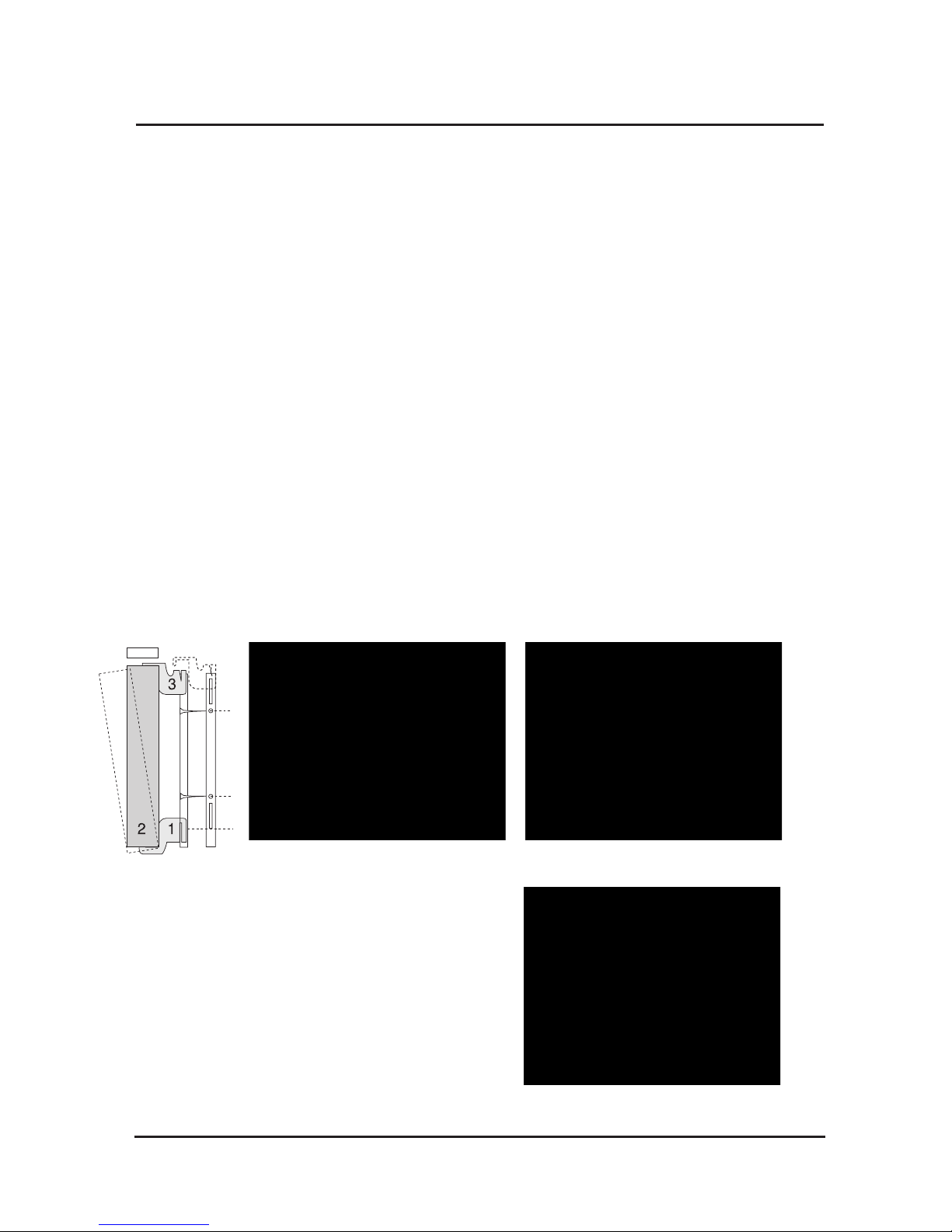
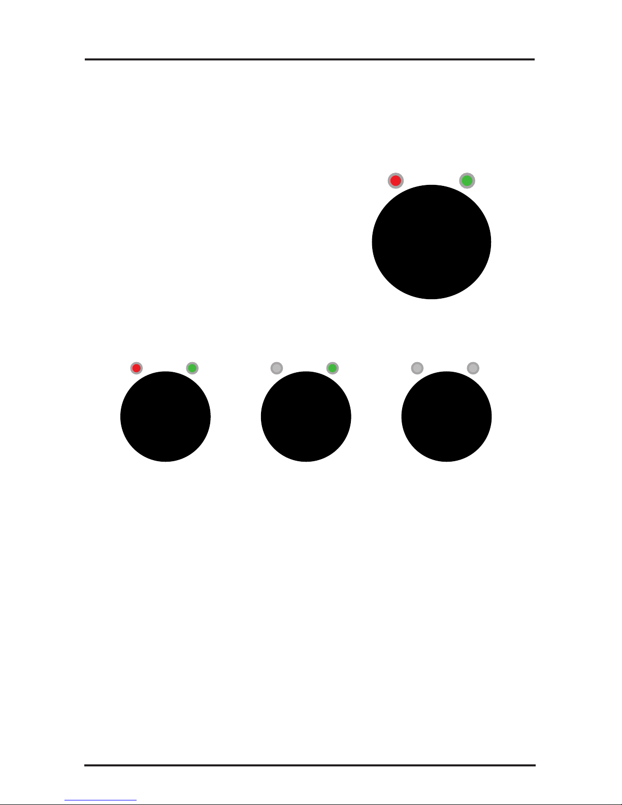
The Keyboard consists of four buttons:
(+ ) Adjustment increase
( ) Adjustment decrease
Mode selection button
Power ‘on/off’ button
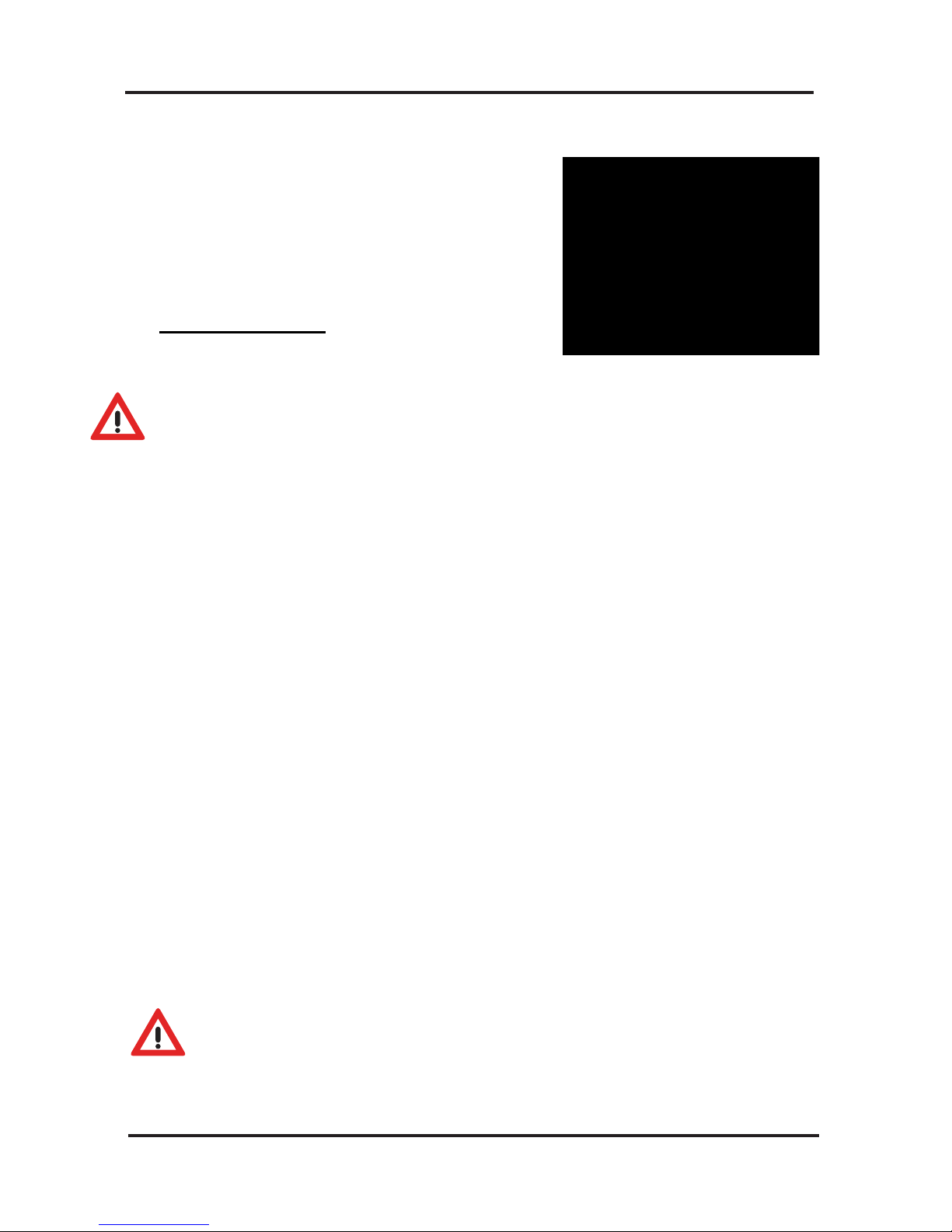
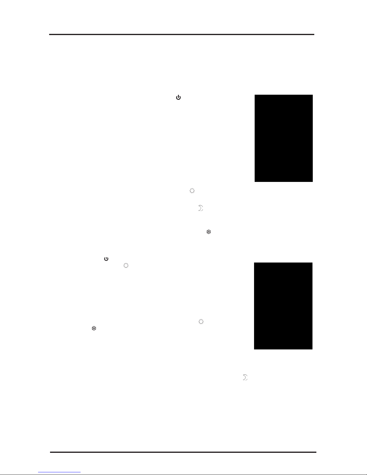
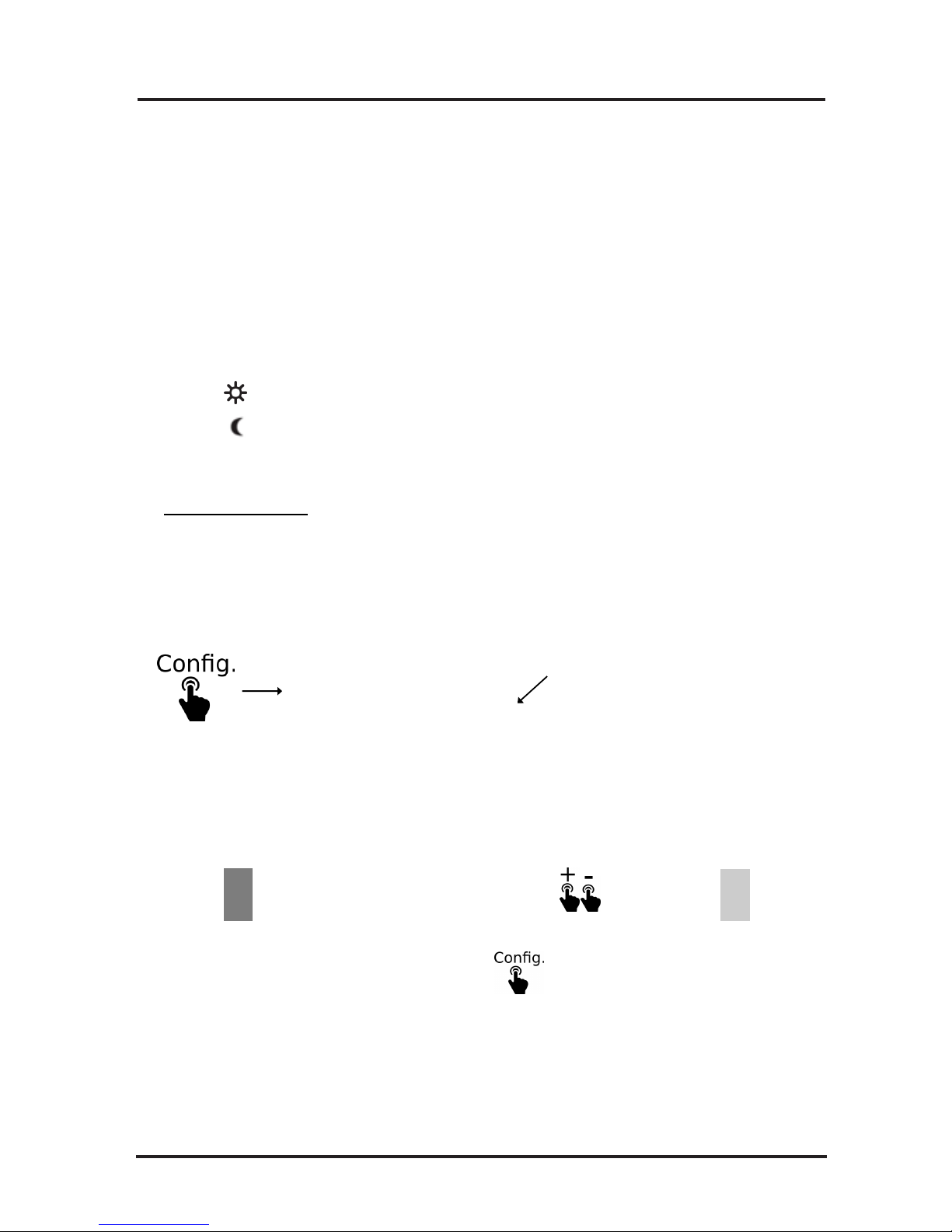
Mode button:
The Mode button has four stages of operation
‘Comfort’ ‘Economy’ ‘Frost Protection’ and
‘OFF’:
>Comfort Mode: The sun icon
is displayed and this is normally used for
day time setting.
>Economy Mode: The moon icon is
displayed and this is normally used for a night
time setting.
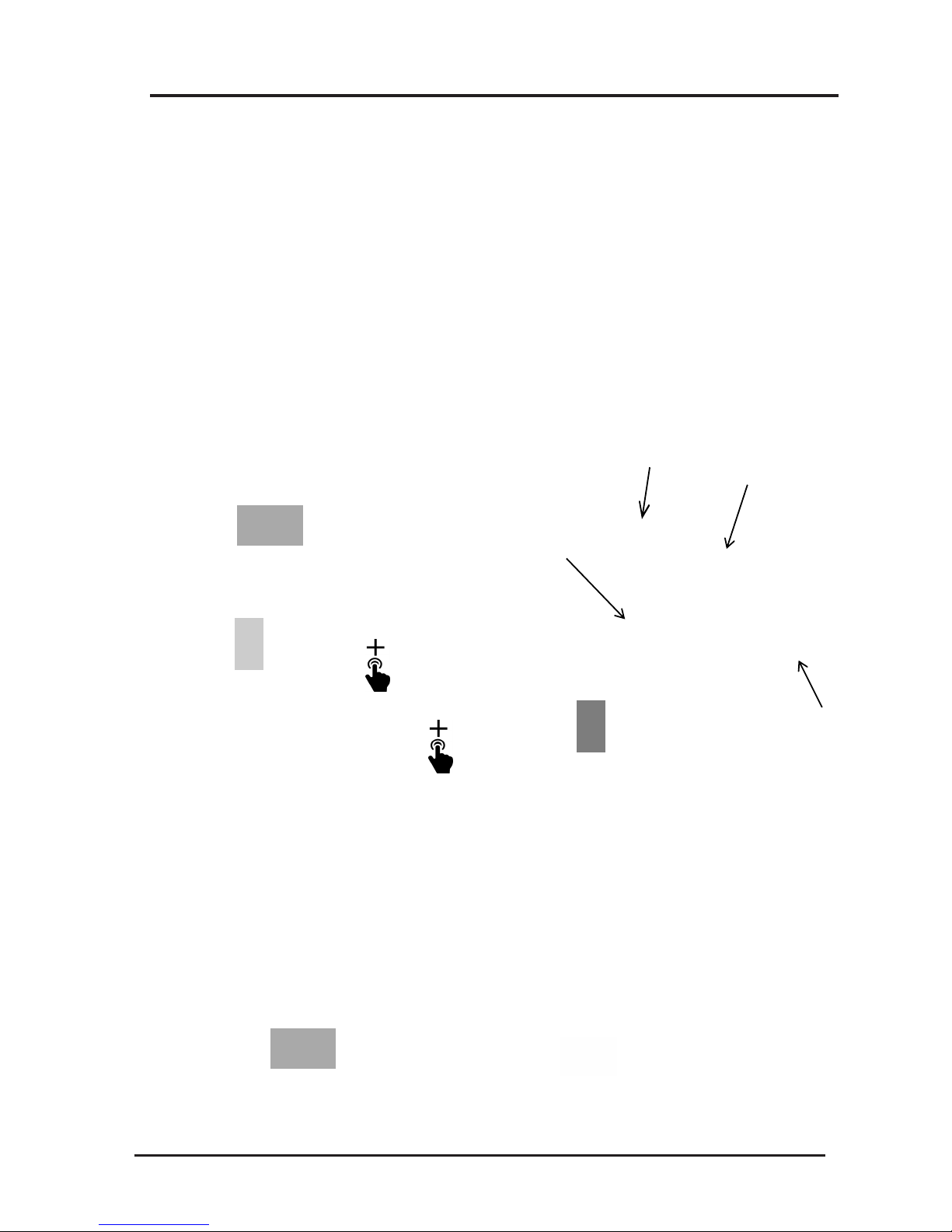
>Frost Protection Mode: The frost icon
is displayed and this is normally used
for periods of absence from the house during
winter months. This is a factory pre-set mode
and is set to 7ºC
>OFF: The digital display will show two small
horizontal bars in-line with each other denoting
that the radiator is still switched on but that no
other program mode is required.
Note.
There will be a 2 deg C difference between
Comfort and Economy settings as default.
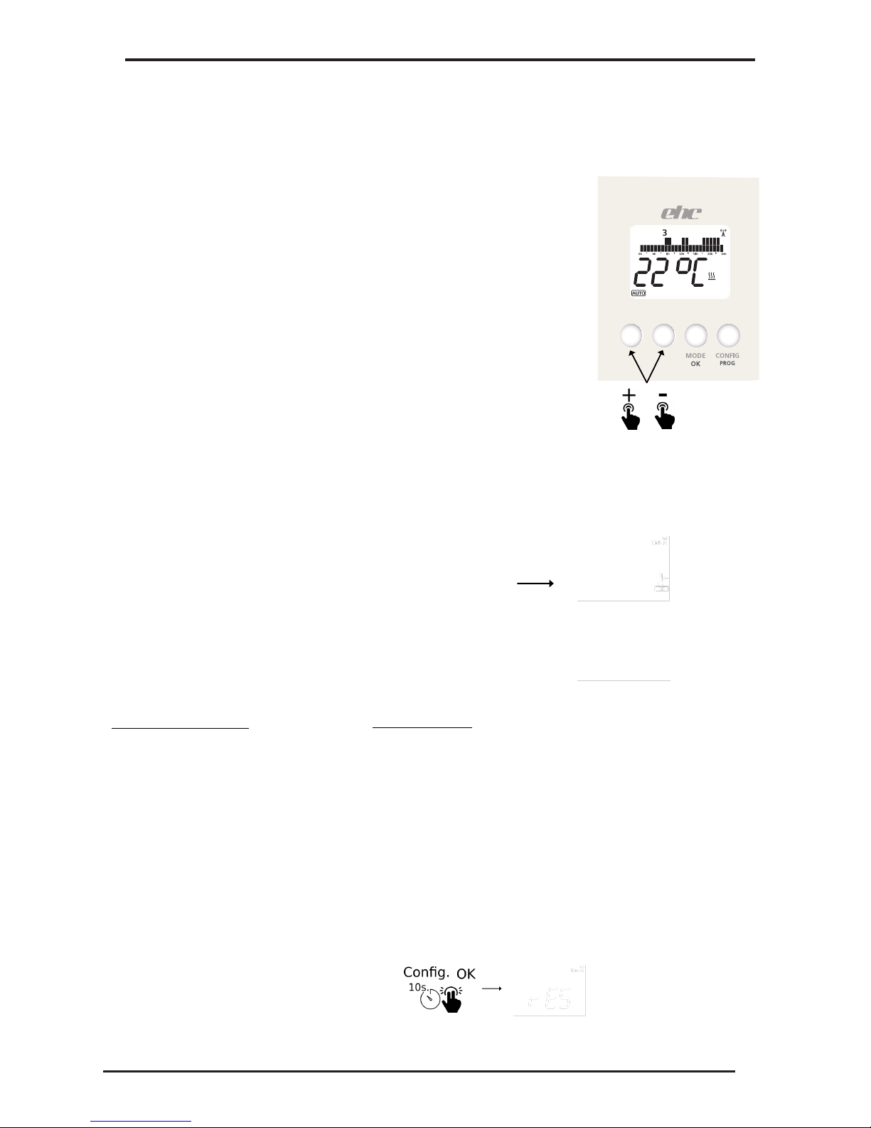
Normal Operation:
Switch the radiator on by pressing the
icon and select either the Comfort or
Economy Mode of operation. This is achieved
by briefly pressing the Mode button until the
desired icon is showing on the digital display.
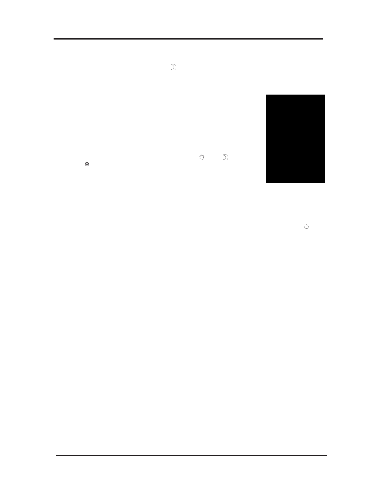
The digital display will also show the current
temperature of the room. To check or set the
desired room temperature briefly press the + or
– button and the digital display will show the
thermostat temperature setting. If you require
the room thermostat temperature setting to be
increased or decreased, briefly press the + or
– button until the desired room thermostat
temperature setting is showing. The digital
display will flash approximately 4 times at 1
second intervals and then the digital display
will stop flashing and display the current room
temperature. If the current room temperature
is lower than the room thermostat temperature
setting you set as above, then the digital
display will show ‘on’ in the upper right section
of the display. This indicates that the radiator
is calling for heat and after a few seconds you
will be able to feel the heat emitting from the
top of the radiator.
Note: The digital display will also show a
clock icon periodically; however this
function is not installed in this radiator and
therefore should be ignored.
Keypad Locking:
To lock the keypad, simultaneously press the
+and – buttons for 5 seconds. After 5 seconds
the ‘LO’ message will be displayed indicating
the keypad is now locked. Once the keypad
has been locked pressing on any button will
display ‘LO’ on the digital display.
To unlock the keypad, simultaneously press
the + and - buttons for 5 seconds, LO message
will disappear and the digital display will revert
back to normal display.
4.Operation Instructions DTi
Page 11

4.Operation Instructions TDi
TDi Instructions for use.
Setting the Time and Day
Step 1:
Step 2:
Step 3:
Step 4:
Step 5:
Step 6:
Ensure the radiator is in OFF Mode. The symbol will be on the top
left of the display.
Push the Right Hand Side mode button once to access the Time and
Day Setting. The days down the right hand side will flash.
Press the + or – buttons to set the day (1 is Monday, 2 is Tuesday,
etc), then press the OK button to confirm.
Press the + or – buttons to set the hour then press OK to confirm.
Press the + or – buttons to set the minutes then press OK to confirm.
Press the Left Hand Side On/Off button once to exit the setting mode.
Setting Temperatures and Program
Sun –
Moon –
Frost –
The sun setting is indicated by the sun symbol and is the setting the user typically uses during
theday.Thesunsettingisnormallysetbetween18and20°Celsius.
The moon setting is indicated by the moon symbol and is the setting the user typically uses
during the night or when the property is vacated for a short period of time. The moon setting is
normallysetbetween15°and17°Celsius.
The frost setting is indicated by the snowflake symbol and is the setting the user typically uses
tohavetheradiatorturnoff.Thefrostsettingisnormallysetat5°Celsius.
STEP 1 – Setting the Desired Room Temperature (Sun Setting)
Push the On/Off button so that the symbol disappears and you can see the sun
symbol at the top of the display.
Press + or – button to set the desired temperature.
Press the small information button below the i symbol on the display to see the
actual current room temperature.
STEP 2 – Setting the Frost Protection Temperature (Frost setting)
Push the Right Hand Side mode button so that the sun symbol disappears and the
snowflake symbol appears.
Press the + or – button to set the frost protection temperature.
This will be the protection temperature that the room will not drop below, even
whentheradiatorisoff.Normally5°or7°Celsius.
STEP 3 – Setting the Set Back Temperature (Moon Symbol)
Push the mode button so that the frost symbol disappears and the moon symbol
appears Press the + or – button to set the set-back temperature.
Set-back temperature is a lower temperature that is usually applied when the property is vacated for a short
period of time (when people are at work), or during the night time (when people are in bed).
If the set-back temperature is being used then the heater will start to work when the room temperature drops
below the chosen setting.
Page 12

Step 1 –
Step 2 –
Push the small button below the PROG symbol.
There will be 00:00 hrs in the middle of the screen, a block flashing on
the left hand side and a triangle pointing to the number 1 (top right
hand side of the screen).
The heater is asking what the temperature / time selection should be
chosen from midnight on Monday.
Across the bottom of the screen there are Sun , Moon and Frost
symbols.
Choose the temperature setting you would like at midnight on a
Monday by pressing the small button under the corresponding symbol.
E.g. most people will use the moon setting while sleeping or when they are away from home.
The screen will now show 01:00 in the middle of the screen, it is now asking what temperature /
time setting you require from 01:00 hrs onwards on that day.
Step 3 – Continue to choose which temperature / time setting you require to be used for each hour of that day.
E.g. if you wanted the radiator to turn on at 06:00 hrs you would press the comfort setting Sun
when the display is showing 06:00 hrs and so forth.
Step 4 – If you want to copy your temperature / time settings from one day to another, this can simply be
done by pressing and holding the small OK button on the RHS. You will see the triangle
pointer moving to the next day. (Your previous settings are now copied to the next day)
Auto Program Overrides
1. Timer Mode
A set temperature can be selected for a certain period of time.
Step 1 –
Step 2 –
Step 3 –
In the auto mode press the button below the hour glass once.
Set the desired temperature with the buttons below the + and – symbols, then press the OK button
to confirm.
Set how long the heater is required to be on with the buttons below the + and – symbols, then
press the OK button to confirm.
The timer will now countdown the time you have set. To cancel the timer mode, press the OK button.
2. Holiday Mode
You can set the radiator to be off if you are going to be absent from the property.
Step 1 –
Step 2 –
Press the suitcase button to select this mode.
Set the number of days of absence by pressing the + or – buttons, then confirm by pressing OK.
While in holiday mode the heaters will keep the room temperature above the frost setting temperature.
To cancel this mode, press on the OK button again.
3. Locking the keypad
Press the – and + button for 5 sec., than a key symbol appears briefly on the display. If you want to unlock the
TDI, press the – and + button again.
STEP 4 – Auto Mode
Push the mode button so that the moon symbol disappears and the auto symbol appears.
In this mode the heater will now follow the temperatures that have been selected for specific times of the day.
The heater has a default profile already displayed.
Choosing a program:
4.Operation Instructions TDi
Page 13

4.Operation Instructions DSR Wifi
DSR Temperature Setting, Programming and Wifi Setup
Page 14
1.0 Manual Instructions
Modes
The radiator can work in 3 different modes by pressing the "Mode" button
Auto Mode
The set temperature varies automatically following the Programmed Schedule, based
on the 3 custom temperatures selected. Each LCD Block indicates what
temperature is active at that time.
Manual Mode
The "Set Temperature" only changes if the user modifies it by pressing the + and -
buttons.
OFF.
The radiator will not heat, but can receive remote instructions if linked to a gateway
that is connected to the internet.
Auto Mode Manual Mode Off
Note:
When in "Auto Mode" manually adjusting the temperature
will Activate the heater for 1.5 hours, after this time period
has lapsed the heater will automatically revert back to the
original program settings.

2.0 Setting Temperatures
4.Operation Instructions DSR Wifi
Page 15
Press
Temperature symbol should be flashing at
this stage,
(if not select by pressing the + or - key)
At Home Sleeping
The DSR controller has 3 temperature ranges,
-Comfort () Normally when at home.
-Economy ( ) Normally used at night or for brief absence periods
-Frost Protection ( ) Normally used when away from home.
To Set Temperatures
to exit.
Now Press Select your temperature, change by pressing the buttons then press to confirm .
Once you have chosen your temperature ranges press
At Work / Away

3.0 Setting Program Time and Day
Symbol Indication
4.Operation Instructions DSR Wifi
Page 16
To start programming.Day of the week
Temperature/hour bar
Hour
Temperature Range
1. Press and hold for 3 seconds.
Sleeping At Work / Away At Home
2. Press To select your temperature range
followed by to set your times by hour.
Select
3. To change the temperature range during programming, Press
temperature then program again using the button.
the controller4. Once you have programmed a 24 hour period
will automatically move onto the the next day. Now program all 7 days
in this way.
Once all 7 days are programmed the controller will then ask you to select the Day of the week (1 being
Monday). Select by pressing the + and - buttons, Save by pressing the OK button. The next stage is to
set the real time. Use the + and - buttons to select the Hour's and Min's, save by pressing OK.
Tip: Quick Real Time Setting.
To change the real time clock without having to go through previous settings.
Press and hold for 3 seconds to show this screen release and press Config
once again to enter Quick Real time settings.

4.0 Keypad Locking
4.Operation Instructions DSR Wifi
Page 17
LOCK
Press and Hold the + and - buttons for 3 seconds to Lock the key pad. All the
buttons will be disabled if pressed. ( LocH will be displayed ) 7RXQORFNSUHVV
DQGKROGWKHDQG%XWWRQVfor 3 seconds.
Configuration Settings
5.0 Advanced Engineer Settings
To enter advance settings,
1. Press the Config button Once to show this screen
2. Now press and hold the Config button for 5 seconds, C1 will now Appear
3. Change Configuration Number by pressing the + or -buttons, then press OK
4. Change the Configuration by pressing the + or - button,Then OK to save.
C1
Factory Defaults
Mode: OFF
Tª comfort: 19ºC
Tª eco: 17ºC
Tª freeze: 5ºC
Tª mode manual: 19ºC
Temperature compensation Offset: 0ºC No
RF link
Temperature units ºC
Open window detection: OFF
Control mode: PID -TRIAC-, PID15 -Relay-
Program: All hours Eco
C1: Temperature unit adjustment ºF/ ºC
C2: Heating control type adjustment
PID15min or PID30min (Factory Set Do
Not Change)
C3: Temperature compensation
adjustment
C4: Firmware version
C5:Open window detection activation
(stops the heating for 30 if a fall of 2,4ºC
is detected over a period of 4 minutes)
Reset Heater to Factory Settings
Press and Hold Config & OK together for 10
Seconds, rES will show on display, Confirm by
pressing OK
Note: Advanced settings should only ever be changed by a fully qualified
engineer or with advice from EHC.

EHC Electric Combination Radiators – Installation and technical manual Page 7
4.Operation Instructions DSR Wifi
Page 18
6.0 Account Registration
To create an account and activate your gateway go to: www.electric-heatingcompany.co.uk/
download/dsr
Click on, "New user,sign up here " Follow the Online instructions to create your account.
Note:
Once registered, you will be sent a Confirmation email. Click on the link to confirm the email to activate
your account then sign in. (If you don’t receive an email, check your Spam folder) You can also setup an
account using the free App's that are downloadable from The Apple App Store & Google Play.
7.0 Setting Up DSR Gateway
1. Attach the Gateway to your internet router using the
Ethernet cable provided.
2. Connect the power supply to the gateway using the micro
USB cable.
3. When energised the Gateways LED's will begin to flash,
Orange ON alternating Green every 5seconds means you are
connected.
Note: If this doesn’t happen check LED sequence list
below.
Gateway LEDs Status
Green off, Orange flashing one second: discovery status (device pairing).
Orange on, Green flashing 0.2 seconds: the router has not assigned an IP address to the gateway.
Orange on, Green flashing briefly every 5 seconds: the router has assigned an IP address to the
gateway correctly, but there is no communication with the server.
Orange on, alternating with green flashing briefly every 5 seconds: the Gateway has connected to
the router correctly and has internet connection.
Note: It is preferable to register your account and gateway before installing it. If it is registered after installation it
may take a few minutes to become accessible via the web, if you do not want to wait, disconnect and reconnect
the power supply to the gateway to reset.

4.Operation Instructions DSR Wifi
Page 19
8.0 Pairing
Once the DSR Gateway is connected to the Internet and fully registered, you can now pair it with your Heaters.
There are 2 ways to put the DSR Gateway into pairing mode.
Option 1.
You can simply press button on the gateway as shown below, the gateway will now
begin searching for external devices.
Option 2.
On your Computer, Smart Phone, or Tablet, select the + install icon at the bottom of the screen, then select the
device you want to install. This will puts the DSR Gateway into pairing mode. An Orange LED will start to flash
on the Gateway, you have 1 minute to add a device at this stage. For each additional new device that is added
the available time increases as you go through the pairing process.
Pairing a Heater with the Gateway
When the Gateway is in pairing mode. Simply press and hold the OK button on the heater for 3
your heater is now connected and ready to program seconds until the Link symbol appears:
through the App.
9.0 Optional Power Meter.
Note:
Installation of this device must be carried out by a competent electrician in accordance with I.E.E. Regulations
for Electrical Equipment. BS:7671
Power Meter
The Power Meter is a device that monitors and helps to protect the main power supply to the property.
From a Computer, Smart phone or Tablet you are able to access and view your total home or heating
systems electrical consumption at any given time.
This manual suits for next models
18
Table of contents
Other EHC Heater manuals
Popular Heater manuals by other brands

Frost Fighter
Frost Fighter IDF500HS Installation - Operation/Maintenance Instructions and Parts List

Somogyi Elektronic
Somogyi Elektronic FK 430 WIFI instruction manual

Serene
Serene S2022 Operating instructions manual

OYPLA Home
OYPLA Home 3680 user manual

HearthRite
HearthRite HR06ML-1 OWNER'S OPERATION AND INSTALLATION MANUAL

Serene
Serene S2088 operating instructions