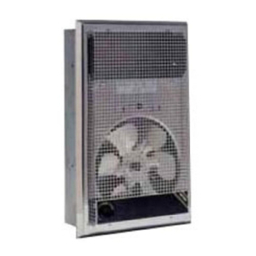
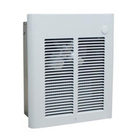
Installation of Recessed Back Box
in New Construction
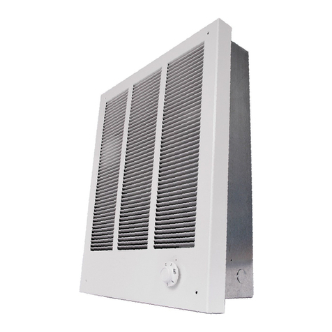
1.Mounting Ba k Box (See Figure 1).
a. Pla e the ba k box between two 16" (506 mm)
enter-to- enter wall studs at the desired mounting
height but no loser than 8" (203 mm) to adja ent wall
or floor.
b. Align ba k box su h that the bottom and sides will be
flush with finished wall surfa e (top flange of ba k box
should protrude approximately 1/2" (12.7 mm) from fin-
ished wall surfa e).
. Se ure the ba k box in position with wood s rews or
nails as shown in Figure 1.
2.Power Supply Wiring (See Figure 1)
Note: Wire ompartment volume - 119in3 (1950 m3).
a. Run a power supply able into the kno kout area in the
upper right hand orner of the ba k box. All wiring must
be in a ordan e with National and Lo al Ele tri al
Codes. Refer to Table 1 for orre t wire size.
b. Remove dis onne t swit h bra ket by loosening two
s rews on the right side.
. Install a able lamp in the “kno kout” in the top of the
ba k box.
d. Insert power supply able through able lamp, allow-
ing at least 6" (152mm) of leads to extend inside the
ba k box. Conne t the blue lead wires of dis onne t
swit h to the supply wire leads using wire onne tors
(see wiring diagram, pg. 3).
e. Ground the ba k box using the green s rew lo ated in
the inside top of the box.
f. Se ure dis onne t swit h bra ket in pla e by tighten-
ing s rews.
Installation of Recessed Back Box
in Existing Construction
1.Provide a wall opening 14-1/2" (362mm) wide by 18-1/2"
(470mm) high at the desired mounting height, but no los-
er than 8" (203mm) to floor (See Figure 2).
2.Power Supply Wiring
Note: Wiring Compartment Volume - 119in3 (1950 m3).
a. Run a power supply able into the area above the top
of the wall opening. All wiring must be in a ordan e
with National and Lo al ele tri al odes. Refer to Table
1 for orre t wire size.
b. Remove dis onne t swit h bra ket by loosening the
two s rews on the right side.
. Install a able lamp in the “kno kout” in the top of ba k
box.
d. Insert power supply able through able lamp, allow-
ing approximately 6" (152mm) of able length to
remain inside the ba k box to fa ilitate onne tions.
3.Mounting Ba k Box
a. Pla e the ba k box into wall opening flush with fin-
ished wall surfa e on bottom and sides of box. (Top
flange of ba k box should protrude approximately 1/2"
or 12.7mm from finished wall surfa e).
b. Se ure the ba k box in pla e with wood s rews or
nails.
4.Wiring Dis onne t Swit h
a. Conne t the power supply wires to the blue wires of the
dis onne t swit h using wire onne tors (see wiring
diagram, pg. 3).
b. Ground the ba k box using the green ground s rew
lo ated in the inside top of the box.
. Se ure dis onne t swit h bra ket in pla e by tighten-
ing s rews.
Installation of Back Box with
Surface-Mounting Frame
(See Figure 3)
1.Se ure ba k box to wall with kno kouts in upper right
hand orner using s rews and an hors.
2.Hang the surfa e-mounting frame on the ba k box.
Ensure that the ba k edge of the surfa e-mounting frame
is flush against the wall.
Fig. 1: Locating Recessed Back Box in New Construction
Fig. 2: Locating Recessed Housing in Existing Construction
2
Back Box
Back Box
CAUTION
FOR SAFE OPERATION AND REDUCED RISK OF FIRE,
INJURY OR HEATER DAMAGE, OBSERVE THE
FOLLOWING:
1. Do NOT use a remote thermostat with this heater. Built in
thermostat y les the heating element only. Fan delay
ontrol automati ally turns fan ON and OFF, and provides
a fan delay OFF feature to remove residual heat
after thermostat has turned heating elements off. Wiring
of heater in any manner whi h defeats the fan delay OFF
feature an result in overheating and permanent dam-
age to heater, and will void the warranty.
2. For wall mounting only with air dis harge downward. Do
NOT install in floor, eiling, upside down(air dis harge
upward), or sideways.
3.Do NOT operate heater without grille installed.
4.Maintain the following learan es:
•Bottom of heater to floor – 8” (203mm)
•Sides of heater to adja ent wall – 8” (203mm)
•Top of heater to eiling – 36” (915mm)
5.This heater is hot when in use. Do NOT install heater
behind door, behind towel ra k, inside loset, where
drapery ould tou h heater or be damaged by heat, or
where airflow to heater may be obstru ted. Keep ele tri-
al ords, bedding, furniture, and other items away from
heater.
6.Heater must be leaned periodi ally (at least annually) to
assure proper performan e and prevent overheating. See
se tion on leaning and maintenan e.
