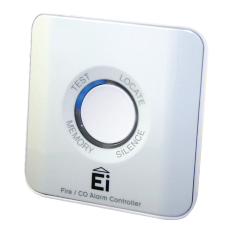
Ei Electronics FC-24 User manual

!
IM0079!2016*08!

2!
Electronics!Inc.!•!!(574)!256*5001!•!www.electronics*inc.com!
!
"#$%&!'(!)'*+&*+,!
-.'/01+!23&.34&5!........................................................................................................................................................!3!
-.4*146%&!'(!26&.#+4'*!.................................................................................................................................................!3!
7#1+'.8!9&(#0%+!:&++4*;,!..............................................................................................................................................!4!
-.&%4<4*#.8!:&++4*;,!.....................................................................................................................................................!5!
Zero!..........................................................................................................................................................................!5!
Full!Scale!Display!Range!...........................................................................................................................................!5!
Alarms!......................................................................................................................................................................!5!
Alarm&Delay!.........................................................................................................................................................!5!
Alarm&Reset!..........................................................................................................................................................!5!
Alarm&Mode!.........................................................................................................................................................!5!
26&.#+4'*!.....................................................................................................................................................................!6!
Setpoint!....................................................................................................................................................................!6!
Enable!.......................................................................................................................................................................!6!
Servo!........................................................................................................................................................................!6!
-.'1&,,!=*60+!:4;*#%!.....................................................................................................................................................!6!
>4.4*;!...........................................................................................................................................................................!7!
:6&14(41#+4'*,!.............................................................................................................................................................!10!
94<&*,4'*,!.................................................................................................................................................................!10!
=*,+#%%#+4'*!.................................................................................................................................................................!11!
?%&1+.'*41,!=*1@!)'*+#1+!=*('.<#+4'*!.........................................................................................................................!12!
A4<4+&/!>#..#*+8!.......................................................................................................................................................!13!
!
B?C9!=D:"BE)"=2D!FCDECA!)2F-A?"?AG!H?72B?!2-?BC"=DI!"J?!7)KLM!)2D"B2AA?B!
!
!
!
!
!
!
!
!
!
!

Electronics!Inc.!•!!(574)!256*5001!•!www.electronics*inc.com!
3!
-.'/01+!23&.34&5!
The! Model! FC*24! Controller! is! used! with! a! MagnaValve®! for! air*blast! and! wheel*blast!shot! peening! and! blast!
cleaning!machines!to!monitor! and! control! the! flow!rate!of!steel!shot!passing!through!the! MagnaValve.! A!digital!
display! indicates! media! flow! rate.! A! 0*10! Vdc! output! signal! proportional! to! flow! rate!is! available! for! remote!
monitoring!or!data!logging.!High/low!alarms!are!set!to!bracket!the!requested!media!flow!rate.!!
!
-.4*146%&!'(!26&.#+4'*!
The!FC*24!provides!and!monitors!closed*loop!control! to! 24!Vdc!MagnaValves!with!a!built*in!sensor.!The!desired!
flow!rate!(Setpoint)!is!compared!to!the!actual!flow!rate!and!a!control!signal!is!sent!to!the!MagnaValve!to!achieve!
the!desired!flow!rate.!If!the!desired!flow!rate!is!not!achieved!within!a!set!time,!which!can!be!adjusted,!a!HIGH/LOW!
ALARM!relay!will!be!triggered.!This!relay!output!contact!may!be!used!to!inhibit!further!machine!operations!and!
notify!the!machine!operator!of!a!potential!problem.!
!
The!diagram!below!illustrates!how!the!FC*24!Controller!provides!accurate!and!dependable!media!flow!control.!
!
!
!
!
!
!
!
!
!
!
A&closed1loop&system&with&the&FC124&Controller&

4!
Electronics!Inc.!•!!(574)!256*5001!•!www.electronics*inc.com!
!
7#1+'.8!9&(#0%+!:&++4*;,!
Adjustments! to! the! factory! default! settings! can! be!made! at! the! Operator! Control!Panel! and! the! Technical!
Adjustments!Panel!(located!behind!the!lower!panel!cover!plate).!
!
)'*+.'%!-#*&%,!
!
!
9&(#0%+!:&++4*;,!
!
H0++'*!D0<$&.!
7&#+0.&!
7#1+'.8!9&(#0%+!:&++4*;!
16!
Alarm!Mode!
%FS!(%!of!Full!Scale)!
4!
Alarm!Bandwidth!
5%!
17!
Alarm!Time!Delay!
5!Seconds!
21!
Enable!Delay!
0!Seconds!
20!
Servo!ON/OFF!
ON!
22!
Enable!Mode!
Ready!
23!
Servo!Adjust!Gain!
65%!
24!
Servo!Adjust!Speed!
55%!
28/29!
Full!Scale!Display!
30.0!
25!
Calibration!*!Span!
1.000!
26!
Calibration!*!Zero!
0.00!Vdc!
!
!
!
!
!
!
!

Electronics!Inc.!•!!(574)!256*5001!•!www.electronics*inc.com!
5!
-.&%4<4*#.8!:&++4*;,!
Note:!Refer!to!Operator!Control!Panel!and!Technical!Adjustment!Panel!diagrams!in!the!“Factory!Default!Settings”!
section!for!location!of!buttons.!
!
N&.'!
The!digital!display!(1)!should!read!0.0!when!the!MagnaValve!is!off.!If!it!does!not!read!0.0,!push!and!hold!the!Zero!
button!(26)!and!use!the!down!button!▼(11)!or!up!button▲(12)!as!required!to!achieve!zero.!
!
70%%!:1#%&!94,6%#8!B#*;&!
The!full*scale!range!is!set!to!match!the!MagnaValve!calibration!(for!example:!30!lb/min).!The!full*scale!range!is!set!
to! 30! lb/min! by! default.! To! display! the! value! of! the! Full! Scale!Display!Range,! press! and! hold! the! Coarse! or!Fine!
Display!Range!button!(28/29).!To!change!the!value,!press!and!hold!the!Coarse!or!Fine!Display!Range!button!(28/29)!
and!use!the!down!button!▼(11)!or!up!button▲(12)!as!required.!
!!
C%#.<,!
The! high! and! low! alarm! relay! contacts! react! when!the! flow! rate! is! lower! or! higher! than! the! alarm!bandwidth!
setting.!The!factory!setting!is!±5%!of!full!scale.!The!center!of!the!Alarm!band!is!the!Setpoint!Command.!To!display!
the!range!of!the!alarm!band,!press!and!hold!the!Alarm!Band!button!(4).!To!change!the!value,!push!and!hold!the!
Alarm!Band!button!(4)!and!push!the!down!button!▼(11)!or!up!button▲(12)!as!required.!!
!
C%#.<!9&%#8!
The! High! Alarm! LED! (2)! or! Low! Alarm! LED! (3)! will! illuminate! whenever! the! flow! rate! is! outside! the! Alarm! Band!
Setting.!These!LEDs! will! get! brighter! at! the! expiration! of! the! alarm!time! delay! and! the!alarm!relay!contacts! will!
transfer!and!latch.!Press!and!hold!the!Alarm!Delay!button!(17)!to!display!the!alarm!time!delay.!The!factory!setting!
for!the!alarm!time!delay!is!5!seconds.!To!modify!this!value,!press!and!hold!the!Alarm!Delay!button!(17)!and!push!
the!down!button!▼(11)!or!up!button▲(12)!as!required.!
!
C%#.<!B&,&+!
Application! of! the! next! enable! signal! will! reset!the! alarm.! Momentary! application! of! 24! Vdc! signal! to! screw!
terminal!12!will!also!reset!the!alarm.!Continuous!application!of!24!Vdc!signal!to!screw!terminal!12!will!disable!the!
alarm.!!
!
C%#.<!F'/&!
Push! the! Alarm! Mode! button! (16)! to! select! either! percent!of! Full*Scale! Range! “%FS”! (14)! (most! common)! or!
percent!of!Setpoint!“%SP”!(15).!The!factory!setting!is!%FS.!
!
!
!
!
!

6!
Electronics!Inc.!•!!(574)!256*5001!•!www.electronics*inc.com!
!
26&.#+4'*!
Note:!Refer!to!Operator!Control!Panel!and!Technical!Adjustment!Panel!diagrams!in!the!“Factory!Default!Settings”!
section!for!location!of!buttons.!
!
:&+6'4*+!!
The!setting!for!the!desired!flow!rate!may!come!from!a!remote!source,!such!as!PLC,!or!it!may!be!set!from!the!FC*24!
Controller.!To!set!or!change!the!Setpoint,!push!the!Setpoint!Local/Remote!button!(27),!select!“Local”,!then!push!
the!Setpoint!button!(8)!to!display!the!value.!To!change!the!Setpoint!value,!push!and!hold!the!Setpoint!button!(8)!
and!use!the!Down!button▼(11)!or!Up!button!▲!(12)!as!required.!
!
?*#$%&!!
The!Mode!button!(22)!will!select!the!enable!status.!The!choices!are!Off,!Ready!and!On.!The!On!mode!will!transmit!
an!enable!signal!to!the!MagnaValve!to!commence!flow.!The!Ready!mode!will!transmit!the!enable!signal!only!when!
a! remote! enable! signal! (from! a! PLC,! for! example)! is! received.! The! Off! mode! prevents! any! operation! of! the!
MagnaValve—it!will!ignore!the!remote!enable!command.!Note:!the!Enable!Delay!(21)!will!delay!the!enable!signal!
to!the!MagnaValve!if!set!greater!than!0!seconds.!
!
:&.3'!
Turn!the!Servo!(20)!On!for!closed*loop!operation.!The!dynamic!operating!parameters!of!the!Servo!are!set!with!the!
Gain! (23)! and! Speed! (24)! buttons.! Gain! and! Speed!are! factory! set! to! typical! values! for!smooth! and! stable!
performance.!The!output!signal!of!the!servo!command!starts!at!zero!media!flow!and!slowly!increases!until!the!flow!
rate!feedback!signal!equals!the!Setpoint!flow!rate!request.!The!Gain!and!Speed!settings!can!be!changed!to!help!
stabilize!the!media!flow!rate!or!to!increase!the!response!time!of!the!MagnaValve.!
!
-.'1&,,!=*60+!:4;*#%!
The! process! input! signal! is! 0*10! Vdc! from! the! MagnaValve.! A! signal! of! 10.0! Vdc! indicates! a! full*scale!
signal!from!the!MagnaValve.!!
!
!
!
!
!
!
!
!
!
!
!
!
!
!
!
!

Electronics!Inc.!•!!(574)!256*5001!•!www.electronics*inc.com!
7!
>4.4*;!
"&.<4*#%!:1O&<#+41!
!
Note:!Refer!to!Operator!Control!Panel!and!Technical!Adjustment!Panel!diagrams!in!the!“Factory!Default!Settings”!
section!for!location!of!buttons!and!LEDs.!Refer!to!the!Terminal!Schematic!above!for!the!location!of!the!terminals.!
!
"&.<4*#%!9&,1.46+4'*,!
L!K!B&<'+&!:&+6'4*+!
Push!the!Setpoint!Local/Remote!button!(27)!until!Remote!Setpoint!LED!(9)!is!on.!Apply!a!0*10!Vdc!analog!signal!to!
the!Remote!Setpoint!terminal!(2).!A!zero!Vdc!signal!will!correspond!to!a!0%!flow!rate!command!and!a!10!Vdc!signal!
will!correspond!to!a!100%!flow!rate!command.!To!display!the!Remote!Setpoint!command,!push!Setpoint!button!
(8).!The!Remote!Setpoint!command!may!come!from!a!remote!potentiometer!or!any!other!0*10!Vdc!signal!source.!
!
M!K!?*#$%&!=*60+!PLM!Q/1R!
When!a!24!Vdc!signal!is!applied!to!the!Enable!Input!terminal!and!the!mode!is!in!the!Ready!state,!the!controller!will!
output! a! 24! Vdc! signal! on! the! Enable! Output! terminal! (9)! and! turn! the! Mode! Status! “On”! LED! (7).! The! Enable!
Output! terminal! (9)! is! normally! connected! to! the! Enable! Input! wire! of!the! MagnaValve! (blue! wire).! The! Enable!
Input!signal!will!reset!alarms!that!occurred!during!the!last!cycle.!
!
S!K!-.'1&,,!=*60+!PTKUT!Q/1R!
This! 0*10! Vdc! process! input! represents! the! flow! rate! of! the! media! through! the! MagnaValve.! Zero! (0)! Vdc! input!
represents!0!lb/min!or!0!kg/min!and!10!Vdc!represents!the!maximum!calibrated!flow!rate!(see!Full!Scale!Display!
Range!under!Preliminary!Settings).!The!signal!is!displayed!on!the!Operator!Control!Panel’s!digital!display!(1).!When!
10!Vdc!is!applied,!the!FC*24!Controller!will!display!the!number!set!for!the!Display!Range!(28/29).!The!Process!Input!
terminal!(6)!is!normally!connected!to!the!Analog!Output!of!the!MagnaValve!(white!wire).!
!
!

8!
Electronics!Inc.!•!!(574)!256*5001!•!www.electronics*inc.com!
!
V!K!-.'1&,,!=*60+!PTKT@W!Q#1R!
This!is!the!0*0.5!Vac!process!input.!It!is!typically!not!used!on!the!FC*24!Controller.!
!
X!K!:&.3'!20+60+!PTKUT!Q/1R!!!
This! is! the! 0*10! Vdc! output.! The! Servo! Output! terminal! (8)! is! connected! to! the! Analog! Input! of! the! attached!
MagnaValve!(orange!wire)!and!controls!the!flow!of!media!through!the!MagnaValve.!Zero!(0)!Vdc!commands!the!
MagnaValve!to!flow!0!lb/min!and!10!Vdc!commands!the!MagnaValve!to!flow!its!maximum!capability.!
!
Y!K!?*#$%&!20+60+!PLM!Q/1R!!!
•When! the!mode! is! in! the! Ready! state! and! an! Enable! Input! signal! is! received,! an! Enable! Output! signal! is!
generated!at!terminal!#9.!
•When!the!mode!is!in!the!On!state,!an!Enable!Output!signal!is!generated!at!terminal!#9.!
•When!the!mode!is!in!the!Off!state,!no!Enable!Output!signal!is!generated!at!terminal!#9.!
The!Enable!Output!terminal!(9)!is!normally!connected!to!the!Enable!Input!wire!of!the!MagnaValve!(blue!wire).!!
!
UL!K!C%#.<!B&,&+!PLM!Q/1R!!
When!a!24!Vdc!signal!is!temporarily!applied!to!the!Alarm!Reset!terminal!(12),!all!alarms!will!be!reset.!If!a!constant!
24! Vdc! signal! is! applied! to! the! Alarm! Reset! terminal! (12),! the! alarms! will! be! held! in! the!reset! state,! essentially!
disabling!them.!
!
UZ!K!C%#.<!J4;O!!
The!Alarm!High!relay!contact!(13)!is!a!normally!open!relay!contact.!The!Alarm!High!relay!contact!(13)!will!close!if!
the!Process!Input!(6)!is!higher!than!the!Setpoint!value!(8)!plus!the!Alarm!Band!value!(4)!for!a!duration!longer!than!
the!Alarm!Delay!(17).!The!Servo!On*Off!(20)!must!be!on!for!alarms!to!work.!
!
UM!K!C%#.<!)'<<'*!!
This!is!a!common!connection!to!all!relays.!
!
UW!K!C%#.<!A'5!
The!Alarm!Low!relay!contact!(15)!is!a!normally!open!relay!contact.!The!Alarm!Low!relay!contact!(15)!will!close!if!the!
Process!Input!(6)!is!lower!than!the!Setpoint!value!(8)!minus!the!Alarm!Band!value!(4)!for!a!duration!longer!than!the!
Alarm!Delay!(17).!The!Servo!On*Off!(20)!must!be!on!for!alarms!to!work.!
!
US!K!7%'5!2[!!
The!Flow!OK! relay!contact!(16)!is!a! normally!open!relay!contact.!The!Flow! OK!relay!contact!(16)!will!close!if!the!
Process!Input!(6)!is!at!the!Setpoint!and!within!the!Alarm!Band!(4)!and!will!remain!closed!for!the!duration!of!the!
blasting!/!peening!cycle.!If!the!Process!Input!(6)! goes! higher!or!lower!than!the!Setpoint!value!(8)!and!the!Alarm!
Band!value!(4)!goes!for!longer!than!the!Alarm!Delay!(17),!the!Flow!OK!relay!contact!(16)!will!open!and!remain!open!
until!the!alarms!are!reset.!The!Servo!On*Off!(20)!must!be!on!for!any!of!the!alarms!to!work!(press!the!Servo!On*Off!
button!(20)!and!ensure!the!Servo!On!LED!(9)!is!lit).!
!
UX!K!B&1'./&.!20+60+!PTKUT!Q/1R!!
This!is!the!0*10!Vdc!analog!output.!The!Recorder!Output!terminal!(18)!is!typically!connected!to!a!PLC!or!some!other!
monitoring!equipment.!The!output!represents!the!flow!rate.!Zero!(0)!Vdc!represents!0!lb/min!flow!rate!and!10!Vdc!
represents!maximum!flow!rate.!
!
!
!

Electronics!Inc.!•!!(574)!256*5001!•!www.electronics*inc.com!
9!
UY!K!-'5&.!PLM!Q/1)!!
The!Power!terminal!(19)!is!the!power!supply!input!to!the!FC*24!controller!and!is!connected!to!the!positive!terminal!
of!the!+24!V!power!supply.!
!
LT!K!)'<<'*!PT!Q/1R!
The! Common! Power! terminal! (20)! is! the! power! supply! return! of! the! FC*24! controller! and! is! connected! to! the!
negative!terminal!of!the!+24!V!power!supply.!
!
!
!
!
!
!
!
!
!
!
!
!
!
!
!
!
!
!
!
!
!
!
!
!
!
!
!
!

10!
Electronics!Inc.!•!!(574)!256*5001!•!www.electronics*inc.com!
!
:6&14(41#+4'*,!
-'5&.!
+24!Vdc!@!0.5!A!
=*60+,!
!
Flow!Sensor!Input!
0*10!Vdc!into!100!K!
20+60+,!
!
Servo!Output!Signal!
0*10!Vdc!
Flow!Enable!Output!
24!Vdc!!
>&4;O+!
1.3!lb/.59!kg!
94,6%#8!B#*;&!
0*1999!
9&14<#%!-'4*+,!
1000,!100.00,!10.0!
C%#.<!H#*/!
0*50%!of!full!scale!
C%#.<!9&%#8!
0*10!seconds!
?*#$%&!9&%#8!
0*10!seconds!
"&<6&.#+0.&!B#*;&!
0˚C!*!50˚C!(32˚F!*!122˚F)!
!
!
94<&*,4'*,!
!
!
!
!
!

Electronics!Inc.!•!!(574)!256*5001!•!www.electronics*inc.com!
11!
=*,+#%%#+4'*!
!
!
!
!
!
!
!
!
!
!
!
!
!
!
!
!
!
!

12!
Electronics!Inc.!•!!(574)!256*5001!•!www.electronics*inc.com!
!
?%&1+.'*41,!=*1@!)'*+#1+!=*('.<#+4'*!
!
F#4%4*;!#*/!:O4664*;!C//.&,,!
Electronics!Inc.!
56790!Magnetic!Drive!
Mishawaka,!IN!46545!USA!
!
"&%&6O'*&!
1*800*832*5653!(Toll*free!in!USA!and!Canada)!or!(574)!256*5001!
!
7#\!
(574)!256*5222!
!
>&$,4+&!
www.electronics*inc.com!
!
For!our!warranty!terms!and!shipping!instructions,!please!read!the!Limited!Warranty.!
!
!
!
!
!
!
!
!
!
!
!
!
!
!
!
!
!
!
!
!
!
!
!

Electronics!Inc.!•!!(574)!256*5001!•!www.electronics*inc.com!
13!
A4<4+&/!>#..#*+8!
7)KLM!)'*+.'%%&.!
!
The!warranty!obligations!of!Electronics!Inc.!for!this!product!are!limited!to!the!terms!set!forth!below.!
!
A&*;+O!'(!>#..#*+8!-&.4'/!
This!limited!warranty!lasts!one!(1)!year!from!the!shipping!date!of!this!product.!
!
>O#+!4,!)'3&.&/!
This!limited!warranty!covers!defects!in!materials!and!workmanship!in!this!product.!
!
>O#+!4,!D'+!)'3&.&/!
This! limited! warranty! does! not! cover! any! damage,! deterioration! or! malfunction! resulting! from! any! alteration,!
modification,!improper!or!unreasonable!use!or!maintenance,!misuse,!abuse,!accident,!neglect,!exposure!to!excess!
moisture,! fire,! improper! packing! and! shipping! (such! claims! must! be! presented! to! the! carrier),! lightning,! power!
surges,! or! other! acts! of! nature.! This! limited! warranty! does! not! cover! any! damage,! deterioration! or! malfunction!
resulting!from!the!installation!or!removal!of!this!product!from!any!installation,!any!unauthorized!tampering!with!
this!product,!any!repairs!attempted!by!anyone!unauthorized!by!Electronics!Inc.!to!make!such!repairs,!or!any!other!
cause! which! does! not! relate! directly! to! a! defect! in! materials! and/or! workmanship! of! this! product.! This! limited!
warranty!does!not!cover!equipment!enclosures,!cables!or!accessories!used!in!conjunction!with!this!product.!!
!
J'5!+'!2$+#4*!#!B&<&/8!E*/&.!+O4,!A4<4+&/!>#..#*+8!
To!obtain!a!remedy!under!this!limited!warranty,!contact!Electronics!Incorporated!by!letter,!email,!fax!or!telephone!
with!the!following!information:!
•Product!name!and!model!
•Product!serial!number!
•Original!shipping!date!(see!label!on!product)!
•Company!name!and!location!
•Name!of!contact!person!for!description!of!symptoms!
•Return!shipping!address!and!any!special!instructions!
!
If!it!is!determined!that!the!product!must!be!returned!under!this!limited!warranty,!a!Returned!Goods!(RG)!number,!
obtained! from! Electronics! Inc.,! will! be! required.! This! product! should! be! properly! packed! to! prevent! damage! in!
transit.! Cartons! not! bearing! a! RG! number! will! require! additional! processing! time! and! repair! service! may! be!
delayed.!
!
>O#+!?%&1+.'*41,!=*1@!>4%%!9'!E*/&.!"O4,!A4<4+&/!>#..#*+8!
Electronics!Inc.!will,!at!its!sole!discretion,!provide!one!of!the!following!remedies!to!whatever!extent!it!shall!deem!
necessary!to!satisfy!a!proper!claim!under!this!limited!warranty:!!
!
1.)! Elect! to! repair! or! facilitate! the! repair! of! any! defective! parts! within! a! reasonable! period! of! time,! free! of! any!
charge!for!the!necessary!parts!and!labor!to!complete!the!repair!and!restore!this!product!to!its!proper!operating!
condition.!Electronics!Inc.!will!pay!the!shipping!costs!necessary!to!return!this!product!once!the!repair!is!complete.!!
!
2.)!If!the!defective!product!cannot!be!repaired,!it!will!be!replaced!with!a!new!unit!and!the!original!warranty!period!
will!be!extended!by!six!(6)!months.!Electronics!Inc.!will!pay!the!shipping!costs!necessary!to!replace!this!product.!

14!
Electronics!Inc.!•!!(574)!256*5001!•!www.electronics*inc.com!
!
!
If!this!product!is!returned!to!Electronics!Inc.,!the!product!must!be!insured!during!shipment,!with!the!insurance!and!
shipping!charges!prepaid.!If!this!product!is!returned!uninsured,!Electronics!Inc.!does!not!assume!any!risk!of!loss!or!
damage! during! shipment.! Electronics! Inc.! will! not! be! responsible! for! any! costs! related! to! the! removal! or! re*
installation!of!this!product.!
!
20+K'(K>#..#*+8!-.'/01+!
Product!that!is!out*of*warranty!will!be!repaired!at!customer’s!request!and!the!cost!of!repair!will!be!disclosed!prior!
to! proceeding! with! the! repair.! A! purchase! order! must! be! received! prior! to! repair.! If! the! product! cannot! be!
repaired,!Electronics!Inc.!will!provide!one!of!the!following!remedies:!
!
1)!New!unit!at!current!pricing!with!a!one!(1)!year!Limited!Warranty!from!the!shipping!date!of!product.!
!
2)!Refurbished!unit!(if!available)!at!a!discounted!price!with!a!six!(6)!month! Limited! Warranty! from! the! shipping!
date!of!product.!
!
A4<4+#+4'*!'*!A4#$4%4+8!
The! maximum! liability! of! Electronics! Inc.! under! this! limited! warranty! shall! not! exceed! the! actual! purchase! price!
paid! for! the! product.! Electronics! Inc.! is! not! responsible! for! direct,! special,! incidental! or! consequential! damages!
resulting! from! any! breach! of! warranty! or! condition,! or! under! any! other! legal! theory! to! the! maximum! extent!
permitted!by!law.!
!
?\1%0,43&!B&<&/8!!
To!the!maximum!extent!permitted!by!law,!this!limited!warranty!and!the!remedies! set!forth!above!are! exclusive!
and!in!lieu!of!all!other!warranties,!remedies! and!conditions,!whether! oral!or!written,!express!or!implied.! To! the!
maximum!extent!permitted!by!law,!Electronics!Inc.!specifically!disclaims!any!and!all!implied!warranties,!including,!
without! limitation,! warranties! of! merchantability! and! fitness! for! a! particular! purpose.! If! Electronics! Inc.! cannot!
lawfully! disclaim! or! exclude! implied! warranties! under! applicable! law,! then! all! implied! warranties! covering! this!
product,!including!warranties!of!merchantability!and!fitness!for!a!particular!purpose,!shall!apply!to!this!product!as!
provided!under!applicable!law.!!
!
B4;O+,!0*/&.!:+#+&!A#5!
This!warranty!defines!specific!legal!rights!relative!to!these!products!provided!by!Electronics!Inc.!Legal!rights!may!
also!vary!from!state!to!state.!
!
Table of contents
Other Ei Electronics Controllers manuals
Popular Controllers manuals by other brands

Gesswein
Gesswein ECO-Torque 280 instruction manual

ETC
ETC ALiEn2 Quick install guide

Altronix
Altronix MaximalV Series installation guide

ICP DAS USA
ICP DAS USA XP-9 88-IoT Series quick start

Roger
Roger AG CTRL Instruction and warnings for the installer

HANA CONTROL ENGINEERING
HANA CONTROL ENGINEERING HN 3200 SERIES user manual