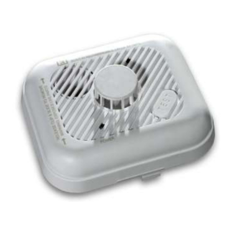
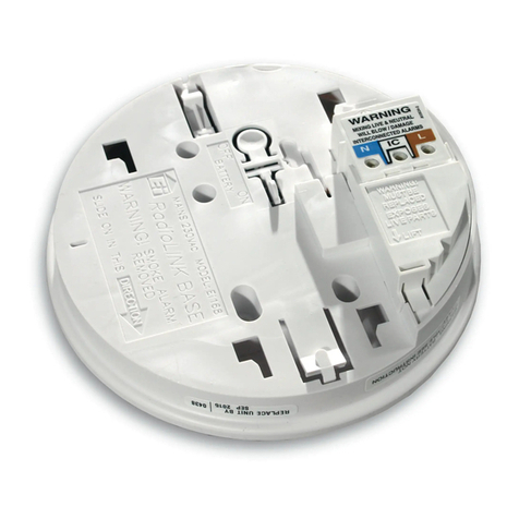
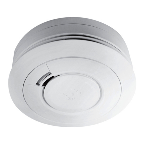
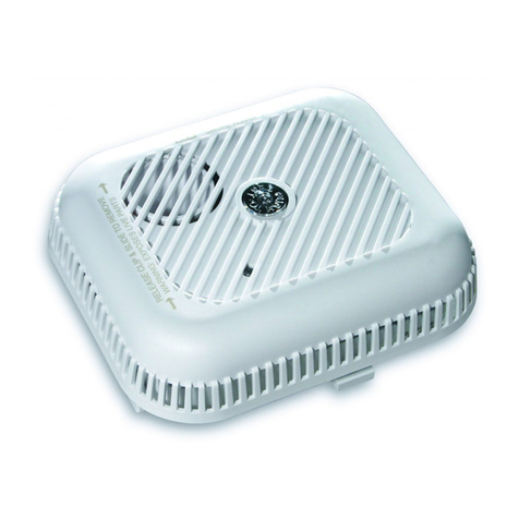
Ei Electronics Ei600 Series User manual

Instructions
Read and retain carefully for as long as the product is being used. It contains vital information on the operation and installation
of your Alarm. The leaflet should be regarded as part of the product.
If you are just installing the unit, the leaflet must be given to the householder. The leaflet is to be given to any subsequent
user.
Ei605 Smoke Alarm Series Ei603 Heat Alarm Series
Battery Powered
Smoke & Heat Alarms
Ei600 Series

Model
Ei605
Note: Certain alarms may be supplied (on request) with the appropriate RF module fitted
Ei605MRF
None
None
Ei605MRF
Ei605MRF
Ei605MRF
Ei605MTYRF
Optional
RF Module
Model No.
Ei605MTYRF
Ei605MTYRF
Ei605MTYRF
Optional
RF Module
Model No.
9V Replaceable Battery
Table 1
Model
10 Year Lithium Battery Built-in
Ei605C
Ei605W
Ei603C
Ei603W
Ei605TYC
Ei605TY
Ei605TYW
Ei603TYC
Ei603TYW
Optical
Optical
Optical
Optical
Optical
Heat
Heat
Heat
Heat
Alarm
Type
Alarm
Type
Optical
No
Yes
No
Yes
No
Yes
No
Yes
No
Hardwired
Interconnect
Hardwired
Interconnect
No
No
Yes
Yes
Yes
Yes
Yes
Yes
Yes
Yes
RF
Capability
Supplied
RF
Capability
Supplied
No

3
Page
CONTENTS
1
2
3
4
5
6
7
8
9
10
11
12
QUICK START GUIDE
LOCATION & POSITIONING
INSTALLATION
INTERCONNECTION - HARD WIRED
TESTING, MAINTENANCE & POWER SUPPLY
MONITORING
FIRE SAFETY ADVICE
SMOKE ALARM LIMITATIONS
RADIOLINK ACCESSORIES
GETTING YOUR ALARM SERVICED
FIVE YEAR GUARANTEE
TROUBLESHOOTING
CONTACT US
4
6
13
17
19
25
28
30
30
31
32
36

4
1. Quick Start Guide
LOCATE CORRECT SITING POINT FIX BASEPLATE TO CEILING
CONNECT BATTERY SNAPS 9V BATTERY MODELS ONLY
ALARM SHOULD BE CEILING MOUNTED AT LEAST 300MM FROM
WALLS & OBSTRUCTIONS, IDEALLY CENTRALLY IN ROOM/AREA
CONNECT THE BATTERY TO THE
BATTERY SNAPS TO POWER THE UNIT
BASE OF
ALARM
9 VOLT
BATTERY
BATTERY
CONNECTORS

ON 10 YEAR LITHIUM BATTERY ALARM
MODELS - TWISTING THE UNIT ON TO
THE BASE AUTOMATICALLY CONNECTS
THE BATTERY
Quick Start Guide
PLACE ALARM & TWIST ON TO BASE
TEST ALARM
TEST ALARM AT LEAST WEEKLY
PRESS THE TEST BUTTON
5

2. Location & Positioning
Introduction
Congratulations on purchasing an Ei600 Series Alarm. You can easily install these
alarms throughout the property on escape routes, on each storey, in corridors & in
closed rooms to give warning of fire.
The Heat Alarms can be installed in kitchens and other areas where Smoke Alarms
are unsuitable.
Models Ei605C/Ei603C/Ei605TYC & Ei603TYC can be interconnected with hard
wiring to give the loudest alarm sound level throughout the house.
All models (except Ei605 & Ei605TY) can be interconnected using the RadioLINK
plug-in modules (These modules must be purchased separately when they are not
supplied with the Alarm (see Table 1)).
Note: Certain alarms may be supplied (on request) with the appropriate RF module
fitted.
SMOKE ALARMS - Ei605 Series
Sufficient smoke must enter your Smoke Alarm before it will respond. Your Smoke
Alarm needs to be within 7.5 metres of the fire to respond quickly. Smoke Alarms
also need to be in positions where they can be heard throughout the property, so
they can wake you and your family in time for everyone to escape. A single Smoke
Alarm will give some protection if it is properly installed, but most homes will require
two or more (preferably interconnected) to ensure that a reliable early warning is
given. For recommended protection you should put individual Smoke Alarms in
all rooms (apart from kitchen and bathroom) where fire is most likely to break out.
6

Your first Smoke Alarm should be located between the sleeping area and the most
likely sources of fire (living room, kitchen for example), but it should not be more
than 7.5 metres from the door to any room where a fire may start and block your
escape from the house.
HEAT ALARMS - Ei603 Series
The Heat Alarm gives a fire warning when the temperature at the Alarm reaches
58°C. It is ideal for kitchens, garages, boiler houses and other areas where there
are normally high levels of fumes, smoke or dust i.e. places where Smoke Alarms
cannot be installed without the risk of excessive nuisance alarms. A Heat Alarm
should only be used in rooms adjoining escape routes, in conjunction with Smoke
Alarms on the escape routes.
All Heat Alarms must be interconnected to the Smoke Alarms to ensure that the
early warning will be heard, particularly by somebody sleeping. A properly designed
early warning fire system ensures the alarm is given before the escape routes
become blocked with smoke. Therefore there must be Smoke Alarms along the
escape routes as Heat Alarms would not give sufficient warning.
However, a fire in a closed room (e.g. kitchen) adjoining the escape route, can
eventually cause the corridor to become smoke-logged due to smoke leaking out
from around the door before adequate warning can be given by detectors in the
corridor. (Smoke leaking out from a room is often cool and slow moving so it can
take a long time to rise to the ceiling, and travel to a detector which could be some
distance away). A Heat Alarm in the closed room will give early warning of fire in that
room and help overcome this problem.
7

8
Multi-Storey Dwellings
If your home has more than one floor, at least one Alarm should be fitted on each
level (see Figure 1). Preferably the units should be interconnected (if feature is
present on unit) so as to give sufficient warning throughout the property. RadioLINK
plug-in modules are ideal in this situation as the units will then interconnect using
Radio Frequency (RF) signals - so no wiring is required.
Figure 1 illustrates where Heat Alarms and Smoke Alarms should be located in a
typical two storey house. Note the spacings in “Protection Levels” which ensure the
early detection of fire and that the warning will be heard.
Locate Heat Alarms in rooms adjoining escape routes - kitchens, garages, boiler
houses etc. where Smoke Alarms are unsuitable. Install within 5.3m of potential
sources of fire.
Single Storey Dwelling
If the premises is one storey you should put your first Smoke Alarm in a corridor or
hallway between the sleeping and living areas. Place it as near to the living area as
possible, but make sure that it can be heard loudly enough in the bedroom to wake
someone. See Figure 2 for placement example.
In houses with more than one sleeping area, Smoke Alarms should be placed
between each sleeping area and the living area and it is recommended that Heat
Alarms should be placed in the kitchen & garage.
Recommended Protection
Fire authorities recommend you put individual Smoke Alarms in or near all
rooms where fire is most likely to break out (apart from the locations to avoid e.g
bathrooms - see Section 3). The living room is the most likely place for a fire to

Bed
r
oom
Bed
r
oom
Bed
r
oom
L
ivin
g
Roo
m
K
it
c
h
en
Ba
thr
oom
D
inin
g
Roo
m
Figure 2
For minimum protection
- Smoke Alarm on each storey
- in each sleeping area
- every 7.5 metres of hallways and
rooms
- within 3 metres of all bedroom doors
- all units interconnected (where
feature is present)
For recommended protection
(in addition to the above):
- Smoke Alarms in every room (except
kitchens and bathrooms)
- Heat Alarms located in kitchens,
garages etc. within 5.3m of potential
fire sources 9
Figure 1

start at night, followed by the kitchen (where a Heat Alarm is recommended) and
then the dining room. Consideration should be given to installing Smoke Alarms in
any bedrooms where fires might occur, for instance, where there is an electrical
appliance such as an electric blanket or heater, or where the occupant is a smoker.
In addition, consideration should be also given to installing Smoke Alarms in any
rooms where the occupant is unable to respond very well to a fire starting in that
room, such as an elderly or sick person or a very young child.
Checking Alarms Can Be Heard
With the Alarms sounding in their intended locations check that the alarm can be
heard in each bedroom with the door closed, above the sound of any TV/audio
systems. The TV/audio systems should be set to a reasonably loud conversation
level. If you cannot hear the alarm over the sound of the TV/audio system, the
chances are it would not wake you. Interconnecting the Alarms using either a
hard-wired interconnection (where the feature is present) or RadioLINK plug-in
modules will help to ensure that the alarm will be heard throughout the property.
Positioning
Ceiling Mounting
Hot smoke rises and spreads out, so a central ceiling position is the recommended
location. The air is “dead” and does not move in corners, therefore Smoke & Heat
Alarms must be mounted away from corners. Keep at least 0.3m from walls and
corners (see Figure 3). Additionally, mount the unit at least 0.3m from any light
fitting or decorative object which might prevent smoke or heat entering the Smoke/
Heat Alarm.
We do not recommend wall mounting these Smoke/Heat Alarms.
10

On a Sloping Ceiling
With a sloping or peaked ceiling install a Smoke Alarm within 600mm of the peak or
a Heat Alarm within 150mm of the peak (measured vertically). If this height is less
than 600mm for Smoke Alarms or 150mm for Heat Alarms the ceiling is regarded
as being flat (see Figure 4).
Locations to avoid
DON’T place Smoke Alarms in any of the following areas:
%DWKURRPVNLWFKHQVVKRZHUURRPVJDUDJHVRU RWKHU URRPV ZKHUHWKH VPRNH
alarm may be triggered by steam, condensation, normal smoke or fumes. Keep
at least 6 metres away from sources of normal smoke/fumes.
/RFDWHDZD\IURPYHU\GXVW\RUGLUW\DUHDVDVGXVWEXLOGXSLQWKHFKDPEHUFDQLPSDLU
performance. It can also block the insect screen mesh and prevent smoke from
entering the smoke detector chamber.
DEAD AIR
SU
RFA
C
E
S
NEVER WITHIN
0
.
3
M
O
F ANY
CO
RNER
IDEAL IN
C
ENTRE
O
F
C
EILIN
G
S
M
O
KE ALARM
S
<600
m
m
HEAT ALARM
S
<
15
0
m
m
APEX
x
x
Figure 3 Figure 4
11

'R QRW ORFDWH LQ LQVHFW LQIHVWHG DUHDV 6PDOO LQVHFWV JHWWLQJ LQWR WKH VPRNH
detector chamber can cause intermittent alarms.
DON’T place Heat Alarms in any of the following areas:
%DWKURRPV VKRZHU URRPV RU RWKHU URRPV ZKHUH WKH XQLW PD\ EH WULJJHUHG E\
steam or condensation.
DON’T place Smoke or Heat Alarms in any of the following areas:
3ODFHV ZKHUH WKH QRUPDO WHPSHUDWXUH FDQ H[FHHG & RU EH EHORZ & HJ
attics, furnace rooms, directly above ovens or kettles etc.) as the heat/steam
could cause nuisance alarms.
1HDU D GHFRUDWLYH REMHFW GRRU OLJKW ILWWLQJ ZLQGRZ PRXOGLQJ HWF WKDW PD\
prevent smoke or heat from entering the Alarm.
6XUIDFHV WKDW DUH QRUPDOO\ ZDUPHU RU FROGHU WKDQ WKH UHVW RI WKH URRP HJ DWWLF
hatches). Temperature differences might stop smoke or heat from reaching the unit.
1H[WWRRUGLUHFWO\DERYHKHDWHUVRUDLUFRQGLWLRQLQJYHQWVZLQGRZVZDOOYHQWVHWF
that can change the direction of airflow.
,QYHU\KLJKRUDZNZDUGDUHDVHJRYHUVWDLUZHOOVZKHUHLWPD\EHGLIILFXOWWR
reach the alarm (for testing, hushing or battery replacement).
/RFDWH WKH XQLW DW OHDVW P IURP GLPPHU FRQWUROOHG OLJKWV DQG ZLULQJ DV VRPH
dimmers can cause interference.
/RFDWHXQLWDWOHDVWPDQGURXWHZLULQJDWOHDVWPDZD\IURPIOXRUHVFHQWOLJKW
fittings as electrical “noise” and/or flickering may affect the unit.
12

3. Installation
Installation Procedure
1. Select a location complying with the advice in Section 2.
2. Remove the mounting plate from the Smoke/Heat Alarm by twisting it in an
anti-clockwise direction (see Figure 5).
3. Place the mounting plate on the ceiling exactly where you want to mount the
Alarm. With a pencil, mark the location of the two screw holes.
4. If interconnecting Alarms using hard-wired
connections, run suitable twin core cabling to
the marked locations of each Alarm. Make
the connections to the Alarm (see Section 4).
5. Taking care to avoid any electrical wiring in
the ceiling, drill holes using a 5.0mm drill bit
through the centre of the marked locations.
Push the plastic screw anchors provided into
the drilled holes. Screw the mounting plate to
the ceiling.
If using RadioLINK Smoke/Heat Alarms then
they should be mounted with antennas in the
same orientation (i.e. essentially parallel).
This means picking a part of the building,
say the front wall of the building and then
installing all mounting plates in the same
ROTATE UNIT ANIT-CLOCKWISE
UNIT WILL NOT TWIST OFF - IT MAY BE
TAMPERPROOFED - SEE FIGURE 8c
Figure 5
13

orientation with respect to this (see figure 6).
6. Connect the battery to the battery snaps as shown in the Quick Start Guide (for
9V Replaceable Battery models only).
7. Carefully line up the unit on the base, gentle press home & twist on. (This
connects the batteries in the 10 Year Lithium Battery models).
Install all the other Alarms similarly.
8. Press the Test button on each alarm to ensure that the Alarm works (see Figure
14
Large
hole
nearest
front
wall
Orientate all
mounting plates
in the same
direction
Front Wall Front Wall
Mounting Plate Mounting Plate
Figure 6

7a for Smoke Alarm & 7b for Heat
Alarm).
9. For hard-wired interconnected
Alarms, hold down the Test button on
each Alarm in turn and check that all
other interconnected Alarms sound.
10. If using RadioLINK
LQWHUFRQQHFWLRQ VHH ERRNOHW ¶5)
0RGXOHVIRU%DWWHU\3RZHUHG6PRNH
& Heat Alarms.
Install all the other Alarms similarly.
Tamperproofing the Alarms
The Alarm can be made tamperproof to prevent unauthorised removal of the Alarm.
%UHDNRIIWKHVPDOOSLOODURQWKHEDVHDVVKRZQLQILJXUHD
To remove the Alarm from the ceiling it is now necessary to use a small screwdriver,
to release the catch (push catch towards the ceiling) and then twist off the alarm
(see figure 8b).
If necessary it is possible to further secure the Alarm by using a No.2 or No.4 (2 to
3mm diameter - not supplied) self tapping screw 6 to 8mm long (see figure 8d), to
firmly lock the Alarm and its mounting plate together (see figure 8c).
Attach the Alarm to the mounting plate.
15
Figure 7a
Smoke Alarm
Figure 7b
Heat Alarm

Line up the screw
(not supplied) on the
“U” shaped recessed
area shown in figure
8c and screw firmly
home.
To remove the Alarm
from the ceiling,
remove the screw
first, and then twist off
anti-clockwise.
16
BREAK OFF
SMALL PILLAR
Figure 8a
How to Tamperproof
PUSH UP CATCH & TWIST
ALARM ANTI-CLOCKWISE TO REMOVE
Figure 8b
How to Remove
6 to 8 mm
2 to 3 mm
SELF TAPPING
SCREW
Figure 8d
TAMPERPROO SCREW
Figure 8c

4. Interconnection - Hard Wired
A combined maximum of 12 Smoke Alarms and/or Heat Alarms may be wired
together such that when one unit senses fire all other units sound a warning - (see
Table 1 for the alarms with hardwired interconnect option). This helps ensure the
alarm will be heard throughout the property.
'RQRWFRQQHFWWRDQ\RWKHUGHYLFHDVLWPD\GDPDJHWKHXQLWRUDIIHFWSHUIRUPDQFH
A maximum of 250 metres of two core, 0.5mm2 to 0.75mm2, stranded signal cable
can be used, (maximum resistance between detectors 50 ohm). The Alarms are
interconnected by wiring all the terminals marked 1 together, and all the terminals
PDUNHGWRJHWKHUVHHLQ)LJXUHD1RWH'UDXJKWVIURPZLULQJRSHQLQJVFRQGXLW
or mounting boxes/holes, may blow smoke away from the sensing chamber,
17
OPE I I
MO I PLA E
Figure 9b
12 12
Figure 9a

making it insensitive. It is essential that all such ceiling openings be closed with
silicone sealant or similar.
1. Run the two core cable to the Alarm locations.
2.%ULQJWKHFDEOHWKURXJKWKHRSHQLQJLQWKHPRXQWLQJSODWHEHIRUHVFUHZLQJLWWR
the ceiling) see figure 9b.
3. If you are bringing the wiring along the surface, break out the two notches (see
figure 10a).
4. Using a small screwdriver, lift off the terminal block by raising it vertically (see
figure 10b).
5. Screw the two cable cores into the terminal block (see figure 10b). Then carefully
press the terminal block back on to the two pins in the base.
6. Twist the Alarm clockwise on to the mounting plate.
18
REAR OF
MO I
PLA E
BREAK O
SI E ALLS
Figure 10a
SCREW
CA LES
INTO
TERMINAL
LOCK
USE SCREW RIVER TO ENTL
LI T OUT THE TERMINAL LOCK
Figure 10b

Install and connect all the other Alarms similarly.
Now test the first Alarm by pressing and holding the Test button (this may take up to
5 seconds). The red indicator light will flash about once a second on the first Alarm
and all other Alarms should sound. Check all the other Alarms similarly.
Note: These Alarms should be interconnected only within the confines of a single
family living unit. If they are connected between different residences there may be
excessive nuisance alarms. Everybody may not be aware that they are being tested
or that it is a nuisance alarm caused by cooking etc.
5. Testing, Maintenance & Power Supply Monitoring
Your Alarm is a life saving device and should be checked periodically. Regularly
check that the red light on the Alarm flashes approx once a minute to show the units
are powered. Replace the Alarm if the flashing stops.
5.1 Manually Testing your Alarms
It is recommended that you test your Alarms after installation and then at least
weekly to ensure the units are working. It will also help you and your family to
become familiar with the sound of the Alarms.
3UHVVDQGKROGWKH7HVW%XWWRQXQWLOWKH$ODUPVRXQGVDQGWKHUHGOLJKWIODVKHV
(see Figure 7a & 7b). The Alarm will stop sounding shortly after the button is
released.
- If the Alarms are interconnected using hard-wired connections, check that all
interconnected Alarms sound.
19

- If they are interconnected using RadioLINK modules, hold down the Test button until
the blue light on the cover of the Alarm illuminates. Check that all other Alarms sound.
- Release the Test button. The Alarm and all connected Alarms should stop
sounding.
- Repeat this procedure for all other Alarms in the system.
WARNING: Do not test with flame.
This can set fire to the Alarm and damage the house. We do not recommend testing
with smoke or heat as the results can be misleading unless special apparatus is used.
When you press the Test button it simulates the effect of smoke in a Smoke Alarm
and heat in a Heat Alarm which they could experience in a real fire. So, there is no
need to test either Alarms with smoke or heat.
5.2 Test/Hush Button to Control Nuisance Alarms
The Smoke Alarms have a combined Test/Hush button to help you control
nuisance/false alarms.
If, when the Alarm sounds, there is no sign of smoke or noise to indicate that there
is a fire, it should be assumed that it is due to an actual fire and the dwelling should
be evacuated immediately.
Check the house carefully in case there is a small fire smouldering somewhere.
Check whether there is some source of smoke or fumes, for example cooking
fumes being drawn past the Alarm by an extractor.
If there are frequent nuisance/false alarms it may be necessary to re-locate the
Smoke Alarm away from the source of the fumes.
20
Other manuals for Ei600 Series
1
This manual suits for next models
12
Table of contents
Other Ei Electronics Security System manuals
Ei Electronics
Ei Electronics Ei Ei168RC User manual

Ei Electronics
Ei Electronics Ei208DWRF User manual

Ei Electronics
Ei Electronics MCP401RC User manual

Ei Electronics
Ei Electronics Ei156TL User manual

Ei Electronics
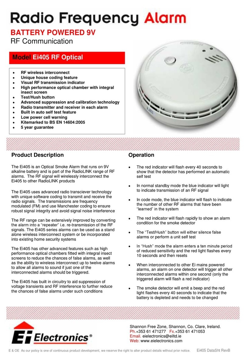
Ei Electronics Ei 405 User manual

Ei Electronics
Ei Electronics RadioLINK Base Smoke & Heat Alarms Ei168 User manual

Ei Electronics
Ei Electronics RadioLINK Ei200MRF User manual

Ei Electronics
Ei Electronics RadioLINK Ei171RF User manual

Ei Electronics
Ei Electronics Ei600 Series User manual
Ei Electronics
Ei Electronics Ei154TL User manual