667 TUBE TESTER ‘
lEICQL, PAGE 5
8. Note the number of lines of settings devoted to the tube in the chart. Each line of
settings corresponds to asection of the tube (1 line for asingle diode, triode or pentode; 2lines
for adouble diode, triode or pentagrid converter; 3lines for aduodide-triode, etc.) Each
section of the tube is tested by making the settings indicated on asingle line of the chart and
then depressing the MERIT lever. Note, however, that twin or triple section tubes having
identical tube characteristics will occupy one line with two or three plate numbers in the merit
column instead of the usual single number. Each of these numbers signifies an individual merit
test. Using the same line of settings, perform each individual merit test.
EXAMPLE: 12AT7, twin triode
In the merit column you will find the entry 16 (one, six). Press 1to read merit of the
first triode. Press 6to read merit of the second triode.
All interelement leakage testing must be performed before any of the Merit tests, as a
safeguard to the tube tester. The push-button which must be pressed down to complete the
leakage and short testing are all given in the same line or different lines for different sections
of the tube. Specific instructions for making settings and performing the required tests follow.
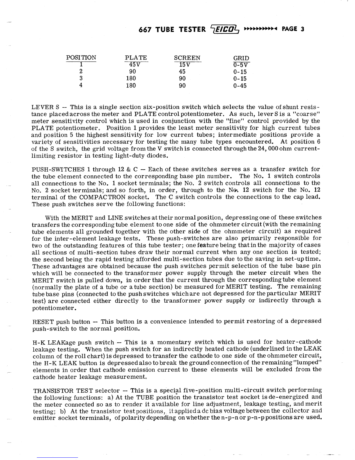
9. The first 3settings following the tube type are for the FIL. selector, GRID control and
PLATE control, in that order. Set these controls accordingly.
10. The next 15 settings are for lever switches 1, 2, 3, 4, 5, 6, 7, 8, 9, 10, 11, 12, C, Vand S
in that order. Set these levers accordingly.
11. Check all settings to make sure that no mistake has been made.
12. Insert the tube into the socket which matches its base. (The socket just above the
TRANSISTOR TEST selector is for transistors only. All other sockets are for tubes only). If
the rectangular sub-miniature socket is used, turn the tube so that its index (red dot, black dot,
glass spur) matches the dot on the panel; then insert each lead into asocket terminal in order,
not skipping any socket terminals starting from the right. If there is atop cap on the tube,
connect it with the cap clip lead.
13. Allow sufficient warm-up time before proceeding. For battery-operated tubes and
h. v. rectifiers (1B3 type) warm up is almost instantaneous; for most receiving tubes 10 to 20
seconds; for high power pentodes, triodes, and rectifiers 20-40 seconds. Note that the MERIT
test (step 17) should not be performed until the stated warm-up time has elapsed.
14. Press the LINE button and note the meter reading. Depending on the filament drain
of the tube under test, the meter will read more or less to the left of the LINE ADJ. mark
(center scale). Holding the LINE button down turn the LINE ADJ. control until the meter
pointer is again over the LINE ADJ. mark. Release the LINE button at the conclusion of this
adjustment.
15. Refer to the first (or only) line of settings for the tube and note the buttons listed in
the LEAK column. Press down each of the buttons listed one at atime (in order), observing
the meter each time. (See next paragraph for evaluation of leakage readings. )The underlined
leakage buttons are for indirectly heated cathodes; when these buttons are depressed, the re-
sulting meter reading will be valid only when the H-K LEAK button is also depressed. Failure
to do so will not normally cause damage to the tube, but will give too low aleakage resistance
reading due to emission to other elements. Thus, the underlined leakage tests are of heater to
cathode leakage only.