Nidec Shimpo DT-315AEB-NIST User manual

Congratulations on your purchase of a Shimpo DT-315AEB
stroboscope/digital tachometer. We trust you will enjoy many
years of professional results from your Shimpo product.
Please read the entire instruction manual thoroughly before
initial set-up and operation; the information contained herein
will aid you in operating your Shimpo stroboscope safely and
with excellent results.
If you have any questions regarding our product(s), call your
local Shimpo representative or contact Shimpo Instruments
directly for assistance.
Inspection/Standard Accessories
If upon delivery shipping damage is detected, do not operate the
unit. Notify shipping carrier immediately for damage claim
instructions. Refertonameplateandrecordserialnumberforfuture
reference. Items included with the DT-315AEB are:
• (1) Handle
• (1) Flash tube removing tool
• (1) External battery pack in carrying bag with shoulder
strap
Instruction Manual
DT-315AEB Stroboscope
Important Safety Instructions
Donotoperateorstoreinstrumentinthefollowingplaces:
explosive areas; near water, oil, dust, or chemicals; areas
where temperature is above 104°F (40°C).
Features and Benefits
Shimpo’s DT-315AEB stroboscope/digital tachometer
incorporates the latest microprocessor technology for visual
inspection applications:
• Aluminum construction provides exceptional durability
• High polish and focused reflector eliminates “blind”
viewing areas
• External trigger allows unit to be automatically
synchronized with equipment
• Continuous duty cycle eliminates need to shut down for
cooling
• Phaseshift allowsvisual analysisof rotating/reciprocating
objects
• High accuracy ( ±0.01% of reading ) is ideal for QC
inspection and process control
• Synchronous output enables strobe to drive other strobes
• Flash timer control conserves flash tube life
Do not disassemble or repair unit while in
operation.
Do not look at the emitted light for long periods
of time; it can be harmful to the eyes.
Set-up
The DT-315AEB may be operated handheld or else mounted on
a tripod for added convenience.
To mount the strobe on a tripod (or any other mounting surface),
use screw ¼ -20unc, length 8mm or shorter for the tripod screw
hole on the bottom.
Donot chargebatterypack for morethan 15- 16
hours.
www. .com information@itm.com1.800.561.8187

OperationDisplay Panel
True RPM Measurement
Shimpo stroboscopes are DUAL function instruments that give
the operator the illusion of “stopped motion” where in actuality
the equipment under observation is in a moving state. By
adjusting the flash rate, equipment in motion appears to be
standingstill. With aslightadjustment, movementcan beviewed
in apparent slow motion, which enables the operator or observer
to study the process in action. All Shimpo stroboscopes can
measure rotational (RPM) or reciprocating (strokes per minute)
speeds with the same high precision as with an electronic digital
tachometer.
To measure true revolutions per minute (RPM):
1. “Mark” the object to be measured by either visually noting
an inherent distinguishing characteristic (such as a label,
scratch, etc.) or physically marking the object with a small
piece of tape, pencil mark, etc.
2. Firmly plug in power cord.
3. Turn power switch on.
4. Turn setter from highest FPM downward.
5. The true RPM can be noted once the action appears frozen
and the first single image of the “mark” appears (see chart
belowand accompanyingdiagram forfurther explanation).
6. To verify RPM reading, press “÷2”; a single image should
appear again.
1. LED display:Displays function and value
2. EXT: External mode indicator
3. INT:Internal mode indicator
4. FPM: Flash per minute indicator
5. deg: Phase shift degree indicator
6. mSec: Millisecond delay time indicator
7. Signalswitch:Switches theunitfrom the externalmode
to the internal mode (and vice-versa)
8. Display mode switch: When unit is set to the external
mode, the strobe will switch to RPM (FPM)/deg/msec
each time “MODE” is depressed
RPM (FPM) Displays flashes per minute
External input 0-35,000 RPM (FPM)
deg Displays flash delay in degrees
msec Displays flash delay in msec
9. Setter: Changes the flashing rate
10. (x2) Switch: In the internal mode, pressing “x2”
doubles the flashing rate
11. (+) Switch: In the internal mode, when object appears
to be standing still, pressing “+” will give the illusion
that the object is moving towards the rotating direction
at a speed of 1 rotation in 6 seconds
12. (÷2)Switch: Intheinternal mode, pressing“÷2”divides
the flashing rate by two
13. (-) Switch:In the internal mode, when object appears
to be standing still, pressing “-“ will give the illusion
thattheobjectismovinginreverseata speed of 1 rotation
in 6 seconds
14. Input and output connector:
PIN #1: +12V
PIN #2: Synch output signal
PIN #3: Input signal
PIN #4: 0V
15. Power cord
16. Power switch
Internal Triggering Mode
To operate the stroboscope in internal triggering mode:
1. Firmly plug power cord into battery pack.
2. Turn power switch on.
3. If internal indicator is not on, press “SIG”; the INT light
will then turn on.
4. Aim light beam at object under observation. The optimal
distance between the strobe and moving object is
approximately 2 feet.
5. Measure RPM by turning the setter to adjust the flashing
rate to the rotational speed of the object.
NOTE: To achieve a particular rate quickly, use the “x2” or
“÷2” switches and then the setter for fine tuning.
NOTE:Once the internal timer has expired, the strobe will stop
flashing and the display will flash rapidly. To restart the strobe,
turn power switch off, then on, and the cycle will repeat.
Shaft Rotation Flashes Flashes/ Stopped
(RPM) (RPM) RPM Shaft Images
6,000 4 times 4
4,500 3 times 3
3,000 2 times 2
1,500 1 time 1
750 1/2 time 1
500 1/3 time 1
At 1,500 RPM
www. .com information@itm.com1.800.561.8187

Operation(continued)
External Triggering Mode
To operate the stroboscope in external triggering mode:
1. Connect external trigger or sensor wires according to
connector pin designation:
1 9.3 - 13.4 VDC (40 mA) for powering sensor
2 Synch output signal
3 External input signal
4 0V (common)
2. Firmly plug in power cord.
3. Turn power switch on.
4. If INT lamp is on, press “SIG” until EXT lamp turns on.
5. Press “MODE” to select proper mode:
FPM Light willflashin correspondence withinputsignal;
the input signal will be calculated into FPM and
displayed.
deg One cycle of input signal is 360°. A delayed angle
will be displayed from 0 up to 359°. (The delayed
angle can be changed by turning the knob setting as
previously described).
msec The above delayed angle will be displayed in msec.
NOTE: If the input signal frequency exceeds upper or lower
limits, the alarm dashes (-----) will be displayed or the strobe
will stop flashing.
NOTE: Once the internal timer has expired, the strobe will stop
flashing and the display will flash rapidly. To restart the strobe,
turn power switch off, then on, and the cycle will repeat.
Synchronous Output Signal
For triggering and controlling additional stroboscopes, the
synchronous output signal appears on pin #2 (see below).
Flash Tube Replacement
When FPM reading is displayed but unit is not flashing, flash
tube may need to be replaced:
1. Unplug line cord from power line.
2. Turn power switch off (wait a few minutes until
stroboscope is cool before proceeding).
3. Remove protective window by removing the 4 screws.
4. Use tube removing tool provided: insert tool all the way
and turn clockwise until tool locks. Pull out tube.
5. Install new flash tube using the removing tool.
6. Replace protective window.
7. Mount reflector in the center so that the reflector will not
interfere with the screw spacer on the corners.
Ifbatteryis low,“LLLLL”is displayed anddisplay will eventually
disappear. Refer to charging instructions provided with the
battery pack.
Battery Charge
FPM Display Mode
If the input signal exceeds 585Hz, the upper dashes on the digital
display will be flashing:
----- upper dashes
If the input signal is lower than 0.67Hz, the lower dashes on the
digital display will be flashing:
----- lower dashes
Deg/msec Display Mode
If the input signal exceeds 167Hz, the upper dashes on the digital
display will be flashing:
(deg) ----- upper dashes ----- (msec)
If the input signal is lower than 0.67Hz, the lower dashes on the
digital display will be flashing:
(deg) ----- lower dashes ----- (msec)
Memory
The following parameters are set at the factory:
• Decimal point: autorange
• Internal timer: continuous
• External trigger edge: L-H (Lo to Hi)
These parameters can be changed in the field to facilitate different
situations. Tochangeanyoftheaboveparameters,followthesesteps:
1. Firmly plug power cord into battery pack.
2. Turn power on.
3. Make sure that INT lamp is on. If not, press “SIG” until it
turns on.
4. Change the desired memory parameter:
a. To change the decimal point
Press “÷2” and “-“ at the same time for approximately
2 seconds until display alternates between —1— and
0.0. Press “+”. The display will freeze and show 0.0.
Change decimal point accordingly by pressing “+”. If
0.0 is selected the decimal point is in the autorange
mode. If 0 is selected the decimal point is eliminated
throughout the entire range.
b. To change the internal timer
Press MODE. The display will alternate between
—2— and 0; press “+”. The display will freeze to 0.
Use the setter to set timer anywhere between 1 and 120
minutes.
c. To change the trigger edge or the external mode
Press MODE. The display will alternate between
—3— and L-H. The external trigger edge is set from
the factory to occur during the positive transition of the
incoming pulse. To change it to the negative transition,
press “+”. Display will change from L-H to H-L.
5. Press “SIG” to go back to normal operation.
NOTE: theabove settingscan be checkedquickly by performing
steps A to C as described above and then pressing “SIG”.
Do not charge for more than 15 - 16 hours.
www. .com information@itm.com1.800.561.8187

LIMITED EXPRESS WARRANTY: Shimpo Instruments warrants, to the original purchaser of new products only, that this product shall be free from defects in workmanship and materials under normal use
and proper maintenance for one year from the date of original purchase. This warranty shall not be effective if the product has been subject to overload, misuse, negligence, or accident, or if the product has been
repaired or altered outside of Shimpo Instruments’s authorized control in any respect which in Shimpo Instruments’s judgment, adversely affects its condition or operation.
DISCLAIMER OFALL OTHER WARRANTIES: The foregoing warranty constitutes the SOLE AND EXCLUSIVE WARRANTY, and Shimpo Instruments hereby disclaims all other warranties, expressed,
statutory or implied, applicable to the product, including, but not limited to all implied warranties of merchantability and fitness.
LIMITATION OF REMEDY: Under this warranty, Shimpo Instruments’s SOLE OBLIGATION SHALL BE TO REPAIR OR REPLACE the defective product or part, at Shimpo Instruments’ option. Shimpo
Instruments reserves the right to satisfy warranty obligation in full by reimbursing Buyer for all payments made to Shimpo Instruments, whereupon, title shall pass to Shimpo Instruments upon acceptance of return
goods. To obtain warranty service, Purchaser must obtain Shimpo Instruments’s authorization before returning the product, properly repackaged, freight pre-paid to Shimpo Instruments.
INDEMNIFICATION&LIMITATIONOFDAMAGES: Buyer agrees to indemnify and hold Shimpo Instruments harmless from and against all claims and damages imposed upon or incurred arising, directly
or indirectly, from Buyer’s failure to perform or satisfy any of the terms described herein. In no event shall Shimpo Instruments be liable for injuries of any nature involving the product, including incidental or
consequential damages to person or property, any economic loss or loss of use.
MERGER CLAUSE: Any statements made by the Seller’s representative do not constitute warranties except to the extent that they also appear in writing. This writing constitutes the entire and final expression
of the parties’ agreement.
Warranty
Dimensions & Specifications
Troubleshooting
FPM reading is displayed but unit is not flashing:
• Flash tube may need to be replaced (see "Flash Tube
Replacement" section)
Stroboscope is in external trigger mode, no flash:
• Check flash tube. Replace if necessary
• Check for damaged wiring and/or loose pin connections
STROBOSCOPE SPECIFICATIONS
ModelModel
ModelModel
Model DTDT
DTDT
DT-315AEB-315AEB
-315AEB-315AEB
-315AEB
INTERNAL MODEINTERNAL MODE
INTERNAL MODE
Flashing RFlashing R
Flashing Rangeange
angeange
ange 40.0 - 35,000 FPM (flashes per minute)
AccuracyAccuracy
AccuracyAccuracy
Accuracy ±0.01% of reading
RR
RR
Resolutionesolution
esolutionesolution
esolution 0.1 FPM: 40.0 - 4,999.9 FPM
0.2 FPM: 5,000 - 7,999.8 FPM
0.5 FPM: 8,000 - 9,999.5 FPM
1 FPM: 10,000 - 35,000 FPM
Phase ShifPhase Shif
Phase Shiftt
tt
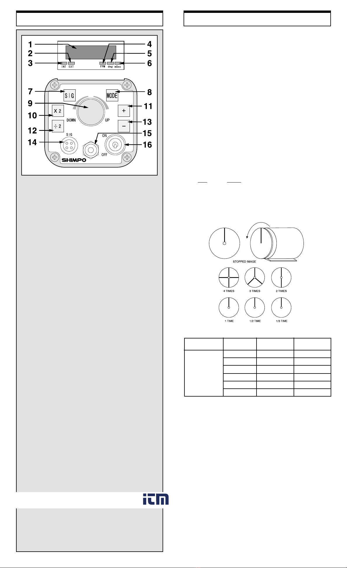
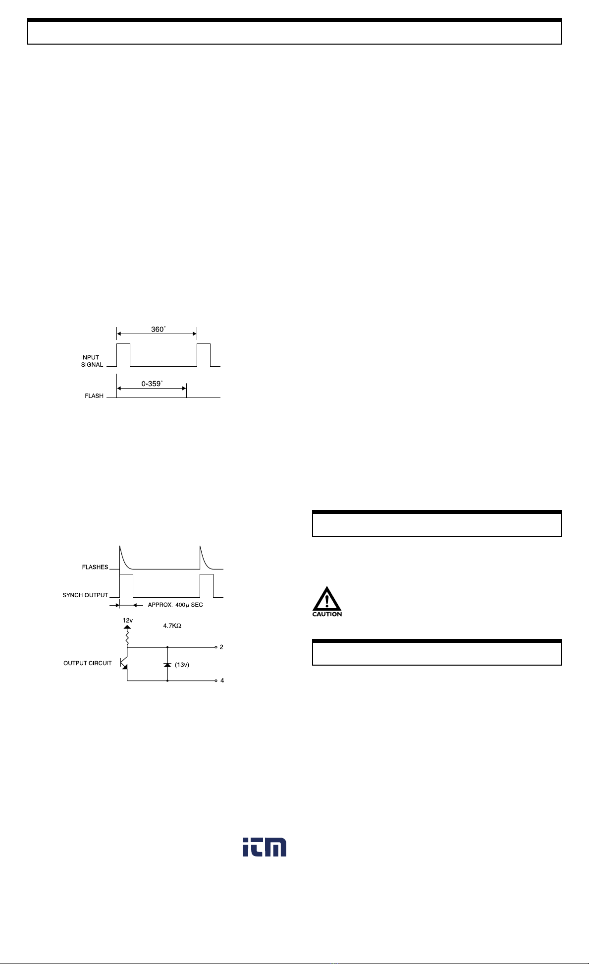
t Use +/- push buttons (360° in 6 seconds)
Display Update TimeDisplay Update Time
Display Update Time 0.2 sec approx.
Output SignalOutput Signal
Output Signal Synchronous, 400 msec. Pulse output, 0 to +12 VDC amplitude(approx.), 4.7 KΩimpedance
RR
RR
Rate Multiplier/Dividerate Multiplier/Divider
ate Multiplier/Dividerate Multiplier/Divider
ate Multiplier/Divider Multiply by 2, divide by 2
EXTERNAL MODEEXTERNAL MODE
EXTERNAL MODE
Flashing RFlashing R
Flashing Rangeange
angeange
ange 0.0 - 35,000 FPM
AccuracyAccuracy
AccuracyAccuracy
Accuracy ±0.01% ±1 digit
Phase ShifPhase Shif
Phase Shiftt
tt
t 0 - 359° with 1° resolution
Delay TimeDelay Time
Delay Time 0 - 2,000 msec from 40 - 10,000 FPM
ExterExter
ExterExter
External Tnal T
nal Tnal T
nal Trigger Input Signalrigger Input Signal
rigger Input Signalrigger Input Signal
rigger Input Signal LO level: 0 - 0.8 VDC, HI level: 2.5 - 12 VDC or open collector (NPN), pulse width 50 msec min.
Input ImpedanceInput Impedance
Input Impedance 4.7 KΩat 12 V / 6.8 KΩat 0 V
GENERGENER
GENERGENER
GENERALAL
ALAL
AL
DisplayDisplay
DisplayDisplay
Display 5 digits, 0.4" (10 mm) high, LED
Flash TFlash T
Flash TFlash T
Flash Tube Pube P
ube Pube P
ube Power/Lifeower/Life
ower/Lifeower/Life
ower/Life Xenon, 10 W max. (100 million flashes)
Flash DurationFlash Duration
Flash Duration 10 - 40 msec
Sensor PSensor P
Sensor PSensor P
Sensor Power Supplyower Supply
ower Supplyower Supply
ower Supply 12 VDC (40 mA)
Low BatterLow Batter
Low Battery Indicatory Indicator
y Indicatory Indicator
y Indicator Display shows all L’s
PP
PP
Power Rower R
ower Rower R
ower Requirementequirement
equirementequirement
equirement Internal Battery Pack
Operating TOperating T
Operating Temperature Remperature R
emperature Remperature R
emperature Rangeange
angeange
ange 32° - 104°F ( 0 - 40°C )
WW
WW
Weighteight
eighteight
eight 2.5 lb (1.1 kg)
DimensionsDimensions
Dimensions 7.28"L x 4.72"W x 4.72"H (185 mm x 120 mm x 120 mm)
WW
WW
Warar
arar
arrantyranty
rantyranty
ranty 1 year
Standard AccessoriesStandard Accessories
Standard Accessories External battery pack with charger
Optional AccessoriesOptional Accessories
Optional Accessories Carrying case
Stroboscope is in internal trigger mode, no flash:
• Check flash tube. Replace if necessary
• Check for damaged wiring and/or loose pin connections
www. .com information@itm.com1.800.561.8187
This manual suits for next models
1
Other Nidec Test Equipment manuals

Nidec
Nidec DT-3015N User manual

Nidec
Nidec DT-3011P User manual

Nidec
Nidec DT-366 User manual

Nidec
Nidec DT-3015P User manual

Nidec
Nidec DT-3011J User manual

Nidec
Nidec Shimpo DT-315AEB User manual

Nidec
Nidec DT-362 User manual

Nidec
Nidec TNC Series User manual

Nidec
Nidec DT-311D User manual

Nidec
Nidec ST-5100 User manual