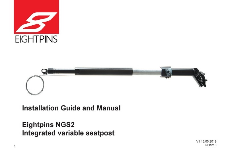
Eightpins NGS1 User manual

EIGHTPINS
Installation Guide and Manual
Eightpins NGS1 –
Integrated Variable Seatpost
Setback + miniSetback
V1.1, NGS1 EN
21.06.18

2
Bild 1
-23,075 mm
-69,225 mm
-115,375 mm
-161,525 mm
Inhalt
7 General
7 Warranty Policy
7 Service
7 Safety instructions
7 Usage as intended
8 Assembly and service
8 Modications
8 Compatibilities
8 Seatpost travel and insert lengths (do not mix up!)
9 Weight limit
9 Before the assembly
10 Manual
10 Using the seatpost
10 Aligning the seatpost / Operating the overload clutch
10 Seat height adjustment top position
10 Adjustment of the saddle angle
10 Before every single ride
11 Assembly instruction
11 Preparationoftheseattubeofyourframe(Drillingaholeforthexationscrew)
11 Adjusting the compensation clip to the frame
12 Cable routing
13 Assembly of the bushing tube and the outer label casing
13 Assembly of the seatpost
14 Assembly of the remote lever
16 Installation of the mini setback saddle
16 Installation of the setback saddle
17 Adjusting the seat height
17 Explanation for the adjustment of the seat height:
18 Adjusting the seat height
19 Stencil for shortening the seatpost
20 Shortening the seatpost tube
21 Reduction of the travel
24 GreasingthebushingtubewithOil
24 Old Version till 03/2018: Greasing the bushing tube
26 Service
26 Dismounting the capsule
27 Cleaning and greasing the bushing tubes
28 Replacing the cable
32 Adjustingthebreakawaytorqueoftheoverloadclutch
33 Installation of the seatpost

3
-23,075 mm
-69,225 mm
-115,375 mm
-161,525 mm
2
45
9 11 12
22
1615
14
17 18
13
8
19 24
25
20
10
3
21
67
23
1
1
Eightpins seatpost tube
2
Eightpins capsule
3
Bushing tube
4
Outer sleeve
5
Teflon ring
6
Felt strip
7
Wiper
8
Plastic fixing screw
9
Spacer 36mm
10
Spacer 24mm
11
Spacer 12mm
12
Spacer 6mm
13
Lubrication port screw
14
Flex aluminium cable housing
15
Remote
16
Clamping nut
17
Cable adjuster
18
End cap small
19
End cap big
20
Valve adapter
21
Seilzug
22
Cable housing
23
EIGHTPINS oil
24
Cutting gauge
25
Travel reduction gauge

4
Bild 1
-23,075 mm
-69,225 mm
-115,375 mm
-161,525 mm
1
2
45
9 11 12
22
1615
14
17 18
13
8
19 24
25
20
10
3
21
67
23
1
Eightpins seatpost tube
2
Eightpins capsule
3
Bushing tube
4
Outer sleeve
5
Teflon ring
6
Felt strip
7
Wiper
8
Plastic fixing screw
9
Spacer 36mm
10
Spacer 24mm
11
Spacer 12mm
12
Spacer 6mm
13
Lubrication port screw
14
Flex aluminium cable housing
15
Remote
16
Clamping nut
17
Cable adjuster
18
End cap small
19
End cap big
20
Valve adapter
21
Bowden cable
22
Cable housing
23
EIGHTPINS oil
24
Cutting gauge
25
Travel reduction gauge

5
-23,075 mm
-69,225 mm
-115,375 mm
-161,525 mm
E
B
C
H
R
Q
S
T
D
A
F
I
G
K
M
N
O
L
P
A
Eightpins seatpost tube
B
Compensation clip
C
Postpin mounting unit
D
Adjusting clamp
E
Piston rod
F
Release slider
G
Guiding insert
H
Bushing tube
I
Eightpins pawls
K
front clamping screw
L
Height adjuster
M
Seatclamp top
N
Seatclamp bottom
O
rear clamping screw
P
Clamping nut
Q
Rotation clutch
R
Eightpins capsule
S Postpin
T
Adjusting ring

6
Bild 1
-23,075 mm
-69,225 mm
-115,375 mm
-161,525 mm
E
B
C
H
R
Q
S
T
D
A
F
I
G
K
M
N
L
O
P
A
Eightpins seattube
B
Compensationclip
C
Postpin mounting unit
D
Adjustingclamp
E
Piston rod
F
Release Slider
G
Guiding inserts
H
Bushing tube
I
Eightpins pawls
K
Seat angles adjuster
L
Height adjuster
M
Seatclamp top
N
Seatclamp bottom
O
Rear clamping screw
P
Clamping nut
Q
Rotation clutch
R
Eightpins capsule
S Postpin
T
adjustng ring

7
-23,075 mm
-69,225 mm
-115,375 mm
-161,525 mm
General
ThankyouforequippingyourbikewithanEightpinsvariableseatpost,ahighstandardized,highlytechnicalproductfor
mountain bikes. There is a variety of points to take into consideration assembling and using the seatpost. As a result
of the integration of the seatpost,
it is designed entirely different in comparison to other variable seatpo
sts. The ad-
justmentoftheseatheightaswellastheadjustmentofthetraveloftheseatpostisrealizedwithonesingletube.The
mechanicsforthisisdirectlyconnectedwiththeframeviathePostpinaxlethatabsorbsallaxialforces.Thelateral
forces are absorbed by the bushing tubes and thus by the frame. It is therefore crucial to mind the maximal travel as
wellastheminimuminsertlength.
Attention! If assembled or used in a wrong way, you may hurt yourself as well as damage the
frame or the seatpost.
Make sure all adjustment elements are in place at all times and that the tension of the cable is adjusted correctly.
In case you do not have the skills to assemble the seatpost, please refer to your local bike dealer or the service center
in your country.
Attention! Read the following assembly information and manual carefully and stepby-step and
mount the Eightpins seatpost only according to the instructions.
Warranty Policy
Weofferatwo-yearswarrantyforyourseatpostbeginningatthedateofpurchase.Ontopofthis,weoffera10-years
warrantyincaseacomponentsuchasthemaintubeorthebushingbreaks.Thewarrantyexclusivelyincludesthe
repairorexchangeofthecomponentsdamaged.Inordertoclaimawarrantycase,thereceiptisobligatory.Common
wear,usualservicesandwrongassembliesarenotcoveredbythewarranty.Iftheseatposthasbeenalteredinany
way,thewarrantyautomaticallyexpires;theriderisresponsibleforanydamagescausedbyanyalterationoftheseat-
post..
Service
As to the service, a major advantage of the Eightpins variable seatpost is that the main tube can be dismounted very
easilyandthattheanti-frictionbushingcanbecleanedand/orexchangedquickly.Incaseyounoticeahigherfriction
in the system, it can be greased via a grease hole in the outer label casing.
With the right tools and a basic technical understanding, you may service the seatpost yourself including cleaning and
greasing the bushings, pumping up the system, readjusting the tension of the overload clutch and exchanging the
cable.
Ingeneral,notmuchservicingisrequired.Thelockingmechanismdoesnotwearout.Incasethegaspressurespring
loses pressure, it is to be sent to us or brought to a local service center, as the sealing needs to be exchanged.
Forservicesofallkinds,pleaserefertoyourlocalbikeworkshoporto„Eightpins“LupaanGmbH:
LupaanGmbH
Hafenstrasse47-51
4020Linz
www.eightpins.at
Attention! Do not service the mechanics or the gas pressure spring yourself as the system is
under high pressure and as one may risk severe injuries.
Safety instructions
Usage as intended
The Eightpins variable seatpost is designed for bicycle frames featuring a Postpin interface. The range of application
includes touring bikes, trekking bikes and mountain bikes. Bicycle frames that do not have this feature should not be
modied..

8
Bild 1
-23,075 mm
-69,225 mm
-115,375 mm
-161,525 mm
TheEightpinsvariableseatpostmustonlybeassembledandcombinedwiththeoriginalEightpinsremotelever.Diffe-
rent leverage ratios can cause irreparable damages.
Assembly and service
TheassemblyandtheserviceoftheEightpinsvariableseatpostrequiresaspecialunderstandingoftechnicalmatters.
DonotoverestimateyourownskillsbutrefertoaprofessionalbicycleshoportoanauthorizedEightpinsservicepart-
neratalltimes.Thisistheonlywayacorrectservicecanbeguaranteed.
Modifi cations
TheEightpinsvariableseatpostisnottobealteredinanyway.Donotdismountit,sanditdownorpaintit.Alwaysuse
atorquewrenchwherenecessary.
Readthemanualcarefullyandfollowitstep-by-step.
Attention: A seatpost that has not been mounted correctly does not work correctly.This may lead
to crashes and injuries. Besides, the frame can be damaged.
Compatibilities
TheintegratedEightpinsvariableseatpostisexclusivelydesignedforframeswitha
Postpininterface.Onecannotretrotthisinterfacetoabicycleframe.Refertoyour
local bike shop in case you are in doubt.
Attention: Eightpins decisively advices its customers not to modify a frame in any way, as this
can weaken the frame, cause crashes and lead to severe injuries including death.
Seatpost travel and insert lengths (do not mix up!)
Attention! do not mix up!
Eightpinsvariableseatpostscomewithaframespecicmechaniccapsuleandbushingswithdifferentmeasurements
asrequiredbythemanufacturers.Thelengthofthebushingtubeisthesameastheactualinsertlengthsinceittrans-
fers the lateral forces into the frame.
Attention! One may exclusively use compatible seatpost diameters, variable seatpost travels
and bushing tube lengths as stated by the manufacturers.
Theseatposttubecomeswith480mmasstandardandneedstobecutwhenadjustedtotheriders’size.Whenthe
tubeisshortened,thepartscutmustnotexceedthemaximumtravel.Pleaserefertothechartbelow..
modell bushingset cartridge max. length
EIGHTPINSNGS1tsLV301MK14XS 100 S+ 282mm
EIGHTPINSNGS1tsLV301MK14S 110 S+ 282mm
EIGHTPINSNGS1tsLV301MK14M 120 M+ 282mm
EIGHTPINSNGS1tsLV301MK14L 130 L+ 282mm
EIGHTPINSNGS1tsLV301MK14XL 140 XL+ 282mm
EIGHTPINSNGS1tsLV301MK14XXL 140 XL+ 282mm
EIGHTPINSNGS1tsLV601MK4S 100 S+ 282mm
EIGHTPINSNGS1tsLV601MK4M 120 M 282mm
EIGHTPINSNGS1tsLV601MK4L 130 L282mm
EIGHTPINSNGS1tsLV601MK4XL 140 XL 282mm
EIGHTPINSNGS1tsLVH-3MK2S 100 S+ 282mm
EIGHTPINSNGS1tsLVH-3MK2M 120 M+ 282mm
EIGHTPINSNGS1tsLVH-3MK2L 130 L+ 282mm
EIGHTPINSNGS1tsLVH-3MK2XL 130 XL+ 282mm
EIGHTPINSNGS1tsLVH-3MK2XXL 140 XL+ 282mm
282

9
-23,075 mm
-69,225 mm
-115,375 mm
-161,525 mm
Weight limit
TheintegratetEightpinsSeatpostissubjectedtoaweightlimit.
SetbackSeatpostmax.riderweight130Kg
MiniSetbackSeatpostmax.riderweight110Kg
Before the assembly
ThePostpininterfaceoftheframefeaturesascrewontheright-handside.Thisscrewismeanttoadjustthevertical
alignmentoftheseatpost,orthogonaltothedirectionofriding.Ithasbeentunedandsecuredwithscrewlockalready.
YourframeistocomewithaPostpinthroughaxleasstandard.

10
Bild 1
-23,075 mm
-69,225 mm
-115,375 mm
-161,525 mm
Manual
Using the seatpost
Inordertolowertheseatpost,pushtheremoteleveratthehandlebarandpushdowntheseatpost.Inordertokeep
thenewsaddleposition,releasetheremotelever.Extendingtheseatpostagain,youneedtopushtheremotelever
andwithoutcounterforceletitnditsoriginalheight.TheEightpinsvariableseatpostworksfullymechanicallyand
features click notches every 6 mm.
Attention: The remote lever must not be pushed if the bike hangs on the saddle.
Aligning the seatpost / Operating the overload clutch
TheEightpinsseatpostfeaturesanoverloadrotationclutch.Thisallowsfortheseatposttoturnawayincaseofa
crash and thus prevents both the saddle and the seatpost from damages. If this has happened, the saddle can simply
bebroughtbackintoplacebyturningit.Ifthebreakawayforceistoolow,itcanbeincreased(refertothechapter
“Service”).
Attention: the saddle can be turned to the left or right with a maximum angle of 90°. If it is turned
further, it will be damaged severely.!
Seat height adjustment top position
Refertothechapter“Seatheightadjustment”.
Adjustment of the saddle angle
Refertothechapter“Installationofthesaddle”.
Before every single ride
Checkthefollowingfunctionsoftheseatpostbeforeeveryride:
- In both rotation directions, there should be no play noticeable.
- The seatpost should not have more play than 2 – 3 mm to the front or back. If the clearance is bigger, check the mini-
muminsertlengthandwhetherthebushingtubeisok(alsorefertothechapter“Service”).
-Thesaddlemustnothaveanyplay,thebackscrewistobetightenedwith8Nm
-Themechanicstolowertheseatpostistorunsmoothlyandwithoutfriction.Incaseyounoticefriction,thebushing
tube is to be greased.
-Theremoteleveristorunsmoothly.Thetensioncableshouldbeadjustedcorrectlywhichyoucandowiththecable
tensionadjuster(refertothechapter:“Cablerouting”).Theleverautomaticallyistogobackintoplacewhenreleased.
If this is not the case, you presumably need to replace the cable.
- Check the function of the click mechanism in the top position, in the bottom position and in an intermediate positions.
If you hear a grinding noise, the cable tension needs to be controlled.
90degrees more than
90 degrees

11
-23,075 mm
-69,225 mm
-115,375 mm
-161,525 mm
Assembly instruction
Preparation of the seat tube of your frame (Drillingaholeforthexationscrew)
1+2Insertthebushingtubeintotheoutertubeupside-down.
3 Put the outer tube including the bushing tube onto the seat tube.
4Theoutertubeistobepushedinwardsuntilthebushingtubesitstightly.
5Makesuretheholeforthegreasingpointstowardsthefrontofthebikeandthattheholeforthexationpoints
towardstheleft-handbackwitha45°angle.Allthisisnecessaryinordertohavetheoutertubeintherightposition
afterwardsandthattheholefortheouterlabelcasingiscongruentwiththedrilledholeintheframe.
6. Witha4.2mmdrillbit,drillaholeintheframefortheplasticxationscrew.Thedrillbitcanbepositionedatthe
outerlabelcasing;makesuretodrillorthogonally.
7. With a M5 thread cutter, cut a thread into the hole.
8. Takeofftheoutertubeanddeburrtheinsideoftheseattubewithsandpaper.
9. Makesurethatnoswarfisleftinsidetheframe.Usecompressedairforthisandturntheframeupside-down..
Attention: The seat tube is to be free of swarf and dirt as this might harm and damage the me-
chanics.
.
Inordertohavetheseatposttubeandtheinnermechanicsbeingalignedintherightway,thesilvercompensation
clip has to be aligned correctly. For this, the entire seatpost must be inserted into the seat tube completely in order to
check the position of the clip at the assembly hole.
1 + 2 Insert the bushing tube into the seat tube from the top. The tube is to go inthere smoothly.
3+4UnscrewthePostpinthroughaxlewitha5mmAllenkey.
5 – 8 Insert the seatpost including the rolled up cable into the seat tube. Make sure the bushing tube does not get
damaged.Thesocketfortheoutercasingaswellasthetopoftheseatpostneedstopointtothebackofthebike.
Attention! The exact align-
ment of the outer tube is to be
minded.
Note:
Slipping the outer label casing
over the seat tube may be dif -
cult. Slightly
altering the initial angle can sim-
plify the matter.
pic. 1 pic. 2 pic. 3 pic. 4
pic. 5
pic. 6 pic. 7
Adjusting the compensation clip to the frame
pic. 8 pic. 9
pic. 1 pic. 2 pic. 3 pic. 4

12
Bild 1
-23,075 mm
-69,225 mm
-115,375 mm
-161,525 mm
9 Insert the seatpost until the compensation clip can be seen from the outside through the Postpin assembly hole. The
slotneedstoberightinthemiddleoftheassemblyhole.Picture12displaystwodifferentwrongpositions.Ifthisisthe
case,theseatpostcanbetakenoutoftheseattubeagaininordertoalignthecliptowardsthefrontorback.Simply
dothiswithyourthumb;youwillnoticeaslightresistance.Repeatsteps5–8thereafter..
1+2RemovethecoveroftheServicePort(refertothemanufacturer’smanual)
3Insertthecablehousingintothespecicholeoftheframe(atthefront)untilittouchesitfromtheinside.
4ThesecondendofthehousingshouldnowbeattheServicePortintheinsideofthedowntube.Pullitoutwithyour
ngers.
Note: exclusively use cable housings with a metal core. Aluminum or plastic housing might not stand the
pressure, which will affect the performance of the mechanics. Shimano SP-41, CAPGO Blueline cable
housing 4 mm.
5NowfurtherpullthecablehousingoutoftheServicePortandformawidesweep.
6 Insert the cable housing into the hole that leads to the seat tube.
7 The cable housing is to be inserted into the seat tube until about 3 cm of it reach out of it. Mind the fact that the sys-
temrequiresawideradiusofthecablehousingatthebottom.
8Thesecondendofthehousing–atthetopoftheframe–istobecutdependingontheframesize.ForLandXLfra-
mes,leaveabout5cm,forM,SandXSframesleaveabout15cm.
pic. 5 pic. 6 pic. 7 pic. 8
pic. 9 pic. 10 pic. 11
Cable routing
Before installing the cable, remove the seatpost and the bushing tube.
pic. 12
pic. 1 pic. 2 pic. 3 pic. 4
pic. 5 pic. 6 pic. 7 pic. 8

13
-23,075 mm
-69,225 mm
-115,375 mm
-161,525 mm
pic. 9
Assembly of the bushing tube and the outer label casing
1 Grease the bushing tube from the outside.
2Insertthebushingtube(withtheangepointingupwardsthebike)intotheframe.Makesurethecablehousingdoes
not damage the bushing tube. Remove unnecessary grease.
3 If necessary, pull the cable housing out of the frame again..
4 + 5 Slip the outer sleeve over the frame being aligned with the hole drilled before.
6.-8. Take the wiper upside down and insert the bended felt stripe in the inner diameter of the wiper bottom.
9. Insert the white wiper ring in the outer sleeve.
10.+11. Press the wiper into the outer label casing; you might face some resistance.
12. With a 5 mm Allen key, carefully screw the plastic screw into the seat tube.
13. With a torque wrench, tighten this screw with 0.5 Nm.
Assembly of the seatpost
Beforeassemblingtheseatpost,unwrapthepreinstalledcable.
1 The Aluminum end cap (big) needs to be slipped over the cable housing that reaches out of the frame.
2 + 3 Insert the cable into the cable housing until it reaches out of it again at the top of the frame.
4HangthecablehousingonthecablehousingcounterpartatthePostpinmountingunitatthelowerendoftheEight-
pins capsule.
Attention: The seatpost needs to be aligned in a way that the top of the seatpost as well as the
cable points towards the back of the bike.
pic. 1 pic. 2 pic. 3 pic. 4
pic. 6 pic. 7 pic. 8
pic. 1 pic. 2 pic. 3 pic. 4

14
Bild 1
-23,075 mm
-69,225 mm
-115,375 mm
-161,525 mm
5 – 7 Tension the cable at the front end of the cable housing and carefully insert the seatpost into the seat tube of the
frame. While inserting the capsule, pull the cable in order to have it under slight pressure at all times and that it does
notslipoutofthesocket.Thisissimpliedbypushingthecablehousingratherthanpullingthecable.
8 Insert the seatpost until you can see the Postpin mounting unit through the hole of the Postpin interface. You must
be able to fully see the slot of the compensation clip through the hole.
9 + 10 Insert the Postpin through axle into the assembly hole and through the Postpin frame interface and tighten it
withatorquewrenchwith8Nm.
ThecablesystemoftheEightpinsseatpostconsistsofacommoncablehousingwithaSteelcoreandashort,more
exiblecablehousingwithanAluminumcoredirectlyattheremotelever.
1Thecablesystemrightattheremoteleverconsistsofa10cmAluminumcablehousing,aspeciccabletensionad-
jusetrandaspecicendcapfortheremoteleverfeaturingareducedouterdiameter.Thespecicendcapisinstalled
at the one end of the cable housing, the cable tension adjuster at the other end. The cable tension adjuster is installed
sothatthesidewiththe4mmlabelisconnectedwiththeAluminumcable
housing. The second end is attached to the steel cable housing that reaches out of the frame..
Note: Initially, put the cable tension adjuster into the minimum cable length position.
pic. 5 pic. 6 pic. 7 pic. 8
pic. 9
Assembly of the remote lever
pic. 10 pic. 11
cable housing
bowden cable
cable adjuster
ex aluminium
cable housing
end cap small
clamping nut
pic. 1
2Installtheremoteleverbetweenthegripandthebrakeleverandtightenitsscrewwith2.5Nm.
Note: The lever can be used with 2-speed drivetrain gear levers and without.
MakesuretheEightpinsremoteleverdoesnotinterferewiththegearlever.Furtherturnitdownwards,inorderto
avoid this.
pic. 2

15
-23,075 mm
-69,225 mm
-115,375 mm
-161,525 mm
3Beforethecableisattachedtoit,pullitrmlyuntiltheclickmechanicsisfullyopen.Youcanhearaslightclickfrom
theinsideoftheseattube.Whenreleasingagain,youwillhearanotherclick.Thisprocessisimportanttoconrm
that all components of the cable system sit tightly.
4Ifthecablehousingcanbepushedintotheframeinanywayduringthecheck,ithasbeendetachedfromthecable
housingcounterpartatthePostpinmountingunit.Takeouttheseatpostandstartagainatstep4“Assemblyofthe
seatpost”onpage13
5Pullthecableclampoftheremoteleveroverthecableandguideitallthewaytothecablehousing.
6+7Veryslightlytightenitsscrewwitha3mmAllenkeyonbothsidessoitcanstill.bemoved.Positionitabout2
mmawayfromthecablehousing.
9Cutthecabledirectlyatthecableclamp.Pullitawayfromthecablehousingalittlebitinordertohavetheendof
thecableitselfdisappearwithinit.
10+11Thedistancebetweencableclampandcablehousingshouldstillnotexceed3mm.
12Tightenthetwoscrewsofthecableclampsimultaneouslywithatorquewrenchwith5Nm..
Attention! In order to avoid injuries, the cable needs to be pulled into the cable clamp hiding any
type of cable bits sticking out of it.
13HoldtheAluminumcablehousingwithyourhand
14 With the other hand, pull the cable in order to open the click mechanism.
15Withthispretension,rsthangtheAluminumcablehousingwiththeendcapontheremotelever.
16 - 18 In the last step, the end cap can be hanged on the remote lever.
.
19 Press the lever in order to control the function of the mechanics.
20Ifthetensionistoolow,youwillfeelalowresistanceatrstbeforeyouthenfeelahigherone.
21Adjustthecabletensionwiththecabletensionadjusterinordertominimizethefreetravel.
22 The cable tension is adjusted correctly if you feel the higher resistance at the last 2 to 3 mm pushing the lever. If
thetensionistoohigh,theclickmechanicsdoesnotopenandtheseatpostcannotbexated.
pic. 3 pic. 4 pic. 5 pic. 6
pic. 7
3mm
pic. 8
5mm
5mm
pic. 9 pic. 10
pic. 11 pic. 12 pic. 13 pic. 14
pic. 15 pic. 16

16
Bild 1
-23,075 mm
-69,225 mm
-115,375 mm
-161,525 mm
1+2Loosenandhangouttherearscrewofthesaddleclamp.
3Assoonthescrewsarelooseenoughremovetheseatclamptop.
4Insertthetopsaddleplateandpositionitoverthesaddlerails.5Hanginthefrontscrewintheholderoftheseatpost
tube head.
6Havethesaddlelayonthesocketsforthesaddlerailsandinsertthebackscrewforthesaddlexationagain.
7Adjustthesaddleanglewiththefrontscrew.Turningitclockwise,thetipofthesaddlemovesdownwards;turningit
anticlockwise,thetipofthesaddlemovesupwards.
8Withan8mmbitandatorquewrench,tightentherearscrewwith8Nm.
ATTENTION: 9. The nuts which are installed in the top seatclamp have two small at areas
which have to be aligned in the long hole parallel to the riding direction.
Note: Altering the saddle angle, you always need to loosen the rear screw rst.
ATTENTION: If the nut are not aligned correctly and the screws get tightened, the nuts get
damaged and can´t move anymore. This can cause a crack of the screws. High risk of injury!
Installation of the setback saddle
1+2Loosenandremovetherearscrewofthesaddleclamp.
3Withthesaddleangleadjustmentscrew,loosenthefrontscrew.
4 Insert the top saddle plate and position it over the saddle rails.
5Havethesaddlelayonthesocketsforthesaddlerails.
6Insertthebackscrewforthesaddlexationagain.
7Withthefrontscrew,adjustthesaddleangle.Turningitclockwise,thetipofthesaddlemovesdownwards;turningit
anticlockwise,thetipofthesaddlemovesupwards.
8Withan8mmbitandatorquewrench,tightentherearscrewwith8Nm.
Note: Altering the saddle angle, you always need to loosen the rear screw rst.
pic. 17 pic. 18
Installation of the mini setback saddle
pic. 19 pic. 20

17
-23,075 mm
-69,225 mm
-115,375 mm
-161,525 mm
Attention: The back screw of the seat post head must not be tightened with more than 8 Nm, as
it might break and lead to an increased risk of injury..
Adjusting the seat height
Explanation for the adjustment of the seat height:
Inordertohavetheseatheightinthepositionwantedwhentheseatpostisfullyextended,ithastobeadjusted
correctly.Asthedesigndoesnolongerincludeaquickrelease,theprocedureissomewhatdifferentfromcommon
systems.TheEightpinsvariableseatpostincludesahigh-pressuregasspring,whichgeneratestheforcetopushthe
seatpostupwards.Thisforceistransferredviaapistonrodandaconnectionelement(seatheightadjustmentclamp)
totheactualseatposttube.Theseatheightadjustmentclamp–turningitclockwise–canbeconnectedtotheseat-
postatdifferentheightpositions.Dependingonthepositionchosen,theseatpostwillalwaysextendagaintoit,afterit
hadbeenlowered.Theseatheightadjustmentclampcanbeoperatedorturnedfromtheoutsideviatheseatpost
height adjuster (Picture 1 and 2) that can be found inside the top of the seatpost. For this, one does not need anything
buta2.5mmAllenkey,withwhichyoumayturntheseatheightadjusterina45°angletoopenorcloseit.3Whenthe
seatheightadjustmentclampisopen,theseatheight–operatingtheremotelever–canbeadjustedwithoutaffecting
thehigh-pressuregasspring.Thisway,theentireseatpostcanberemoved,also.Theactualseatheightisadjusted
whentheseatheightadjustmentclampisopenandtheremoteleveratthehandlebarispushedsimultaneously.
Releasetheremoteleverandhavetheseatpostclickintoplacewhereyouwantit.Closetheseatheightadjustment
clampagainbyturningthe2.5mmAllenkeyclockwisefor45°.
.
Attention! It is important to have the seat height adjustment clamp closed at all times when ri-
ding your bike. In case the mechanics are jammed, move the seatpost tube up- and downwards
slightly and simultaneously turn the seat height adjustment clamp clockwise.
pic. 1 pic. 2 pic. 3 pic. 4
pic. 5 pic. 6 pic. 7 pic. 8
seat angles adjuster
height adjuster
rear clamping screw
5mm allen key, 8Nm
pic. 1
height adjuster rear clamping screw
5mm allen key, 8Nm
front clamping screw, 5mm
allen key, 8Nm
pic. 2 pic. 3

18
Bild 1
-23,075 mm
-69,225 mm
-115,375 mm
-161,525 mm
Adjusting the seat height
4Goforarsttestrideandadjusttheseatheightwiththeremotelever5-10Iftherightseatheightisreachableleave
thesaddleheightinthechosenposition.Thenturntheheightadjuster45°witha2.5mmallenkeycounterclockwise.
Youwillnoticeaslightclicknoisewhenthepistonrodinsidetheseatpostndsbackintoplace.Thenturntheheight
adjuster45°clockwisetolocktheheightadjustmentsystemagain.5-10Ifthehighestpositionistoolowduringthe
testride,turntheheightadjuster45°counterclockwisewitha2.5mmallenkey.11Pushtheremoteleverandpullthe
seatposttubeoutfurther.12Afterthisprocess,makesuretheseatposttuberemainsinbothbushingstube,which
means that it still sits in them. If the sesatpost is not guided in both bushings it has a lot of play. 5-10 The moment the
seatheightisinthepositionyouwantittobein,turntheheightadjuster45°clockwisewitha2.5mmallenkeytolock
the height adjustment system again. The seat height has been adjusted.
The concept of shortening the seatpost tube
With the goal to have the maximum travel of your Eightpins variable seatpost for your individual seat height, the seat-
postneedstobeshortened.Iftheseatpostistoolong,itwillnothaveenoughspaceinsidetheframeforthefulltravel
whenlowered.Beforeshorteningtheseatpost,theidealseatheightistobeevaluated.Thereferencepointforthe
followingmeasurementisthetopendofthewiper.Aftertheshortening,theseatpoststillneedstobelongenoughto
beguidedbythetwobushings.Thetwobushingsareguidedinthebushingtube.Thistubeisavailablewithdifferent
lengthsdependingontheframesizeandtheindividualinsertlength.Thedistancebetweenthetwobushingtubes
equalstheinsertlengthoftheseatpostintheframeanddependsontheframe.Thetubeneedstobelongenoughin
ordertoguaranteefortheminimuminsertlengthwhentheseatpostisfullyextended.Ifthetubeistooshort,andifit
isthusnotguidedbythetwobushings,theframeortheseatpostcanbedamaged.Thestencilisdesignedinawayto
leave some tolerance of the seat height if you change your pedals, your shoes or your saddle..
pic. 1
Attention! The seatpost tube needs to be
guided by both bushings. This means that-
the minimum insert length is to be minded
as you risk damaging your frame or inju-
ringyourself.
min
max
-6
-12
-18
-24
-30
-36
-42
-48
-54
-60
-66
min
max
-6
-12
-18
-24
-30
-36
-42
-48
-54
-60
-66
max
-6
-12
-18
-24
-30
-36
-42
-48
-54
-60
-66
-72
-78
-84
min
min
max
-6
-12
-18
-24
-30
-36
-42
-48
-54
-60
-66
-72
-78
-84
-90
-96
max
min
max
-6
-12
-18
-24
-30
-36
-42
-48
-54
-60
-66
-72
-78
-84
-90
-96
-102
-108
S
L
XL
M
travel reduction in mm
XS
XXL/
range 160-190mm
recommended 178mm
range 150-180mm
recommended 168mm
range 140-170mm
recommended 158mm
range 130-160mm
recommended 148mm
range 120-150mm
recommended 138mm
range 160-190mm
recommended 178mm
range 150-180mm
recommended 168mm
range 140-170mm
recommended 158mm
range 130-160mm
recommended 148mm
range 120-150mm
recommended 138mm
pic. 2

19
-23,075 mm
-69,225 mm
-115,375 mm
-161,525 mm
Stencil for shortening the seatpost
Theseatpostcomeswithastencilforshorteningitcorrectly.ThesizesXStoXLrefertothedifferentframesizes.The
referencepointforthemeasurementandthereforethepointtoattachthestenciltoisthetopendofthewiper.After
theadjustment,markthepositionwithsometape,removetheseatpostandpositionthestencilatthebottomlineof
thetape–downwards.
Thestencildisplaysagreenandaredscaleineverycolumn,dependingontheframesize.Ifthetubeiscutinthe
greenarea,thefulltraveloftheseatpostwillbeavailable.Ifitiscutintheredarea,thetravelneedstobereduced
withtravelreductionspacersinordertoavoidacollisionoftheseattubewiththePostpinxationinsidetheframe
(picture1).Ifthetravelshallbereduced,refertotheredarea.Ifthetubereachesintoanewboxonthescaleonly
slightly, refer to this box and mount reduction spacers respectively. For further information, also read the chapter
“Reductionthetraveloftheseatpost”.
4. Cuttingthetubeatthelowerendofthegreenarea:theseatheightcanbeincreasedafterwardsmorethaninpoint
3,howeveritcannotbedecreasedwithoutreducingthetravel.
5. Cuttingthetubeatthetopendofthegreenarea:theseatheightcanbedecreasedafterwardsmorethaninpoint3,
howeveritcannotbeincreasedagain.
Intermediate recommendation:
6. Cuttingincombinationwithatravelreduction:ifyouwanttohavelesstravel,youstillhavemorepossibilitiesto
increasetheseatheightafterwards.Thetravelneedstobereducedwithspacersasdisplayedonthescale.Alsorefer
tothechapter“Reductionofthetravel”.
min
max
-6
-12
-18
-24
-30
-36
-42
-48
-54
-60
-66
min
max
-6
-12
-18
-24
-30
-36
-42
-48
-54
-60
-66
max
-6
-12
-18
-24
-30
-36
-42
-48
-54
-60
-66
-72
-78
-84
min
min
max
-6
-12
-18
-24
-30
-36
-42
-48
-54
-60
-66
-72
-78
-84
-90
-96
max
min
max
-6
-12
-18
-24
-30
-36
-42
-48
-54
-60
-66
-72
-78
-84
-90
-96
-102
-108
S
L
XL
M
travel reduction in mm
XS
XXL/
range 160-190mm
recommended 178mm
MK14
range 150-180mm
recommended 168mm
range 140-170mm
recommended 158mm
range 130-160mm
recommended 148mm
range 120-150mm
recommended 138mm
range 160-190mm
recommended 178mm
range 150-180mm
recommended 168mm
range 140-170mm
recommended 158mm
range 130-160mm
recommended 148mm
range 120-150mm
recommended 138mm
min
max
-6
-12
-18
-24
-30
-36
-42
-48
-54
-60
-66
min
max
-6
-12
-18
-24
-30
-36
-42
-48
-54
-60
-66
max
-6
-12
-18
-24
-30
-36
-42
-48
-54
-60
-66
-72
-78
-84
min
min
max
-6
-12
-18
-24
-30
-36
-42
-48
-54
-60
-66
-72
-78
-84
-90
-96
max
min
max
-6
-12
-18
-24
-30
-36
-42
-48
-54
-60
-66
-72
-78
-84
-90
-96
-102
-108
S
L
XL
M
travel reduction in mm
XS
XXL/
range 160-190mm
recommended 178mm
MK14
range 150-180mm
recommended 168mm
range 140-170mm
recommended 158mm
range 130-160mm
recommended 148mm
range 120-150mm
recommended 138mm
range 160-190mm
recommended 178mm
range 150-180mm
recommended 168mm
range 140-170mm
recommended 158mm
range 130-160mm
recommended 148mm
range 120-150mm
recommended 138mm
-6
-12
-18
-24
-30
-36
-42
-48
-54
-60
-66
0
-6
-12
-18
-24
-30
-36
-42
-48
-54
-60
-66
-72
-78
-84
0
-6
-12
-18
-24
-30
-36
-42
-48
-54
-60
-66
-72
-78
-84
-90
-96
0
-6
0
-12
-18
-24
-30
-36
-42
-48
-54
-60
-66
-72
-78
-84
-90
-96
-102
-108
XS/S
150mm travel
L
192mm travel
XL/XXL
216mm travel
M
168mm travel
travel reduction in mm
-6
-12
-18
-24
-30
-36
-42
-48
-54
-60
-66
0
-6
-12
-18
-24
-30
-36
-42
-48
-54
-60
-66
-72
-78
-84
0
-6
-12
-18
-24
-30
-36
-42
-48
-54
-60
-66
-72
-78
-84
-90
-96
0
-6
0
-12
-18
-24
-30
-36
-42
-48
-54
-60
-66
-72
-78
-84
-90
-96
-102
-108
XS/S
150mm travel
L
192mm travel
XL/XXL
216mm travel
M
168mm travel
travel reduction in mm
min
max
-6
-12
-18
-24
-30
-36
-42
-48
-54
-60
-66
min
max
-6
-12
-18
-24
-30
-36
-42
-48
-54
-60
-66
max
-6
-12
-18
-24
-30
-36
-42
-48
-54
-60
-66
-72
-78
-84
min
min
max
-6
-12
-18
-24
-30
-36
-42
-48
-54
-60
-66
-72
-78
-84
-90
-96
max
min
max
-6
-12
-18
-24
-30
-36
-42
-48
-54
-60
-66
-72
-78
-84
-90
-96
-102
-108
S
L
XL
M
travel reduction in mm
XS
XXL/
range 160-190mm
recommended 178mm
MK14
range 150-180mm
recommended 168mm
range 140-170mm
recommended 158mm
range 130-160mm
recommended 148mm
range 120-150mm
recommended 138mm
range 160-190mm
recommended 178mm
range 150-180mm
recommended 168mm
range 140-170mm
recommended 158mm
range 130-160mm
recommended 148mm
range 120-150mm
recommended 138mm
bushing 1
bushing 2
seatpost
no travel reduction
keine Hub reduzierung
travel reduction 66mm
Hub reduzierung um 66mm
pic. 3
Highlyrecommended:
3. Cuttingthetubeinthemiddleofthegreenarea(asmarkedwiththescissorsymbol).Inthiscase,theseatheight
canstillbealteredafterwardswhilestillofferingthefulltravel.
Not recommended:
min
max
-6
-12
-18
-24
-30
-36
-42
-48
-54
-60
-66
min
max
-6
-12
-18
-24
-30
-36
-42
-48
-54
-60
-66
max
-6
-12
-18
-24
-30
-36
-42
-48
-54
-60
-66
-72
-78
-84
min
min
max
-6
-12
-18
-24
-30
-36
-42
-48
-54
-60
-66
-72
-78
-84
-90
-96
max
min
max
-6
-12
-18
-24
-30
-36
-42
-48
-54
-60
-66
-72
-78
-84
-90
-96
-102
-108
S
L
XL
M
travel reduction in mm
XS
XXL/
range 160-190mm
recommended 178mm
MK14
range 150-180mm
recommended 168mm
range 140-170mm
recommended 158mm
range 130-160mm
recommended 148mm
range 120-150mm
recommended 138mm
min
max
-6
-12
-18
-24
-30
-36
-42
-48
-54
-60
-66
min
max
-6
-12
-18
-24
-30
-36
-42
-48
-54
-60
-66
max
-6
-12
-18
-24
-30
-36
-42
-48
-54
-60
-66
-72
-78
-84
min
min
max
-6
-12
-18
-24
-30
-36
-42
-48
-54
-60
-66
-72
-78
-84
-90
-96
max
min
max
-6
-12
-18
-24
-30
-36
-42
-48
-54
-60
-66
-72
-78
-84
-90
-96
-102
-108
S
L
XL
M
travel reduction in mm
XS
XXL/
range 160-190mm
recommended 178mm
MK14
range 150-180mm
recommended 168mm
range 140-170mm
recommended 158mm
range 130-160mm
recommended 148mm
range 120-150mm
recommended 138mm
-6
-12
-18
-24
-30
-36
-42
-48
-54
-60
-66
0
-6
-12
-18
-24
-30
-36
-42
-48
-54
-60
-66
-72
-78
-84
0
-6
-12
-18
-24
-30
-36
-42
-48
-54
-60
-66
-72
-78
-84
-90
-96
0
-6
0
-12
-18
-24
-30
-36
-42
-48
-54
-60
-66
-72
-78
-84
-90
-96
-102
-108
XS/S
150mm travel
L
192mm travel
XL/XXL
216mm travel
M
168mm travel
travel reduction in mm
-6
-12
-18
-24
-30
-36
-42
-48
-54
-60
-66
0
-6
-12
-18
-24
-30
-36
-42
-48
-54
-60
-66
-72
-78
-84
0
-6
-12
-18
-24
-30
-36
-42
-48
-54
-60
-66
-72
-78
-84
-90
-96
0
-6
0
-12
-18
-24
-30
-36
-42
-48
-54
-60
-66
-72
-78
-84
-90
-96
-102
-108
XS/S
150mm travel
L
192mm travel
XL/XXL
216mm travel
M
168mm travel
travel reduction in mm
min
max
-6
-12
-18
-24
-30
-36
-42
-48
-54
-60
-66
min
max
-6
-12
-18
-24
-30
-36
-42
-48
-54
-60
-66
max
-6
-12
-18
-24
-30
-36
-42
-48
-54
-60
-66
-72
-78
-84
min
min
max
-6
-12
-18
-24
-30
-36
-42
-48
-54
-60
-66
-72
-78
-84
-90
-96
max
min
max
-6
-12
-18
-24
-30
-36
-42
-48
-54
-60
-66
-72
-78
-84
-90
-96
-102
-108
S
L
XL
M
travel reduction in mm
XS
XXL/
range 160-190mm
recommended 178mm
MK14
range 150-180mm
recommended 168mm
range 140-170mm
recommended 158mm
range 130-160mm
recommended 148mm
range 120-150mm
recommended 138mm
bushing 1
bushing 2
seatpost
no travel reduction
keine Hub reduzierung
travel reduction 66mm
Hub reduzierung um 66mm
pic. 4
min
max
-6
-12
-18
-24
-30
-36
-42
-48
-54
-60
-66
min
max
-6
-12
-18
-24
-30
-36
-42
-48
-54
-60
-66
max
-6
-12
-18
-24
-30
-36
-42
-48
-54
-60
-66
-72
-78
-84
min
min
max
-6
-12
-18
-24
-30
-36
-42
-48
-54
-60
-66
-72
-78
-84
-90
-96
max
min
max
-6
-12
-18
-24
-30
-36
-42
-48
-54
-60
-66
-72
-78
-84
-90
-96
-102
-108
S
L
XL
M
travel reduction in mm
XS
XXL/ range 160-190mm
recommended 178mm
MK14
range 150-180mm
recommended 168mm
range 140-170mm
recommended 158mm
range 130-160mm
recommended 148mm
range 120-150mm
recommended 138mm
range 120-150mm
recommended 138mm
min
max
-6
-12
-18
-24
-30
-36
-42
-48
-54
-60
-66
min
max
-6
-12
-18
-24
-30
-36
-42
-48
-54
-60
-66
max
-6
-12
-18
-24
-30
-36
-42
-48
-54
-60
-66
-72
-78
-84
min
min
max
-6
-12
-18
-24
-30
-36
-42
-48
-54
-60
-66
-72
-78
-84
-90
-96
max
min
max
-6
-12
-18
-24
-30
-36
-42
-48
-54
-60
-66
-72
-78
-84
-90
-96
-102
-108
S
L
XL
M
travel reduction in mm
XS
XXL/
range 160-190mm
recommended 178mm
MK14
range 150-180mm
recommended 168mm
range 140-170mm
recommended 158mm
range 130-160mm
recommended 148mm
range 120-150mm
recommended 138mm
min
max
-6
-12
-18
-24
-30
-36
-42
-48
-54
-60
-66
min
max
-6
-12
-18
-24
-30
-36
-42
-48
-54
-60
-66
max
-6
-12
-18
-24
-30
-36
-42
-48
-54
-60
-66
-72
-78
-84
min
min
max
-6
-12
-18
-24
-30
-36
-42
-48
-54
-60
-66
-72
-78
-84
-90
-96
max
min
max
-6
-12
-18
-24
-30
-36
-42
-48
-54
-60
-66
-72
-78
-84
-90
-96
-102
-108
S
L
XL
M
travel reduction in mm
XS
XXL/
range 160-190mm
recommended 178mm
MK14
range 150-180mm
recommended 168mm
range 140-170mm
recommended 158mm
range 130-160mm
recommended 148mm
range 120-150mm
recommended 138mm
pic. 5
min
max
-6
-12
-18
-24
-30
-36
-42
-48
-54
-60
-66
min
max
-6
-12
-18
-24
-30
-36
-42
-48
-54
-60
-66
max
-6
-12
-18
-24
-30
-36
-42
-48
-54
-60
-66
-72
-78
-84
min
min
max
-6
-12
-18
-24
-30
-36
-42
-48
-54
-60
-66
-72
-78
-84
-90
-96
max
min
max
-6
-12
-18
-24
-30
-36
-42
-48
-54
-60
-66
-72
-78
-84
-90
-96
-102
-108
S
L
XL
M
travel reduction in mm
XS
XXL/ range 160-190mm
recommended 178mm
MK14
range 150-180mm
recommended 168mm
range 140-170mm
recommended 158mm
range 130-160mm
recommended 148mm
range 120-150mm
recommended 138mm
min
max
-6
-12
-18
-24
-30
-36
-42
-48
-54
-60
-66
min
max
-6
-12
-18
-24
-30
-36
-42
-48
-54
-60
-66
max
-6
-12
-18
-24
-30
-36
-42
-48
-54
-60
-66
-72
-78
-84
min
min
max
-6
-12
-18
-24
-30
-36
-42
-48
-54
-60
-66
-72
-78
-84
-90
-96
max
min
max
-6
-12
-18
-24
-30
-36
-42
-48
-54
-60
-66
-72
-78
-84
-90
-96
-102
-108
S
L
XL
M
travel reduction in mm
XS
XXL/
range 160-190mm
recommended 178mm
MK14
range 150-180mm
recommended 168mm
range 140-170mm
recommended 158mm
range 130-160mm
recommended 148mm
range 120-150mm
recommended 138mm
range 120-150mm
recommended 138mm
min
max
-6
-12
-18
-24
-30
-36
-42
-48
-54
-60
-66
min
max
-6
-12
-18
-24
-30
-36
-42
-48
-54
-60
-66
max
-6
-12
-18
-24
-30
-36
-42
-48
-54
-60
-66
-72
-78
-84
min
min
max
-6
-12
-18
-24
-30
-36
-42
-48
-54
-60
-66
-72
-78
-84
-90
-96
max
min
max
-6
-12
-18
-24
-30
-36
-42
-48
-54
-60
-66
-72
-78
-84
-90
-96
-102
-108
S
L
XL
M
travel reduction in mm
XS
XXL/
range 160-190mm
recommended 178mm
MK14
range 150-180mm
recommended 168mm
range 140-170mm
recommended 158mm
range 130-160mm
recommended 148mm
range 120-150mm
recommended 138mm
pic. 6
min
max
-6
-12
-18
-24
-30
-36
-42
-48
-54
-60
-66
min
max
-6
-12
-18
-24
-30
-36
-42
-48
-54
-60
-66
max
-6
-12
-18
-24
-30
-36
-42
-48
-54
-60
-66
-72
-78
-84
min
min
max
-6
-12
-18
-24
-30
-36
-42
-48
-54
-60
-66
-72
-78
-84
-90
-96
max
min
max
-6
-12
-18
-24
-30
-36
-42
-48
-54
-60
-66
-72
-78
-84
-90
-96
-102
-108
S
L
XL
M
travel reduction in mm
XS
XXL/ range 160-190mm
recommended 178mm
MK14
range 150-180mm
recommended 168mm
range 140-170mm
recommended 158mm
range 130-160mm
recommended 148mm
range 120-150mm
recommended 138mm
min
max
-6
-12
-18
-24
-30
-36
-42
-48
-54
-60
-66
min
max
-6
-12
-18
-24
-30
-36
-42
-48
-54
-60
-66
max
-6
-12
-18
-24
-30
-36
-42
-48
-54
-60
-66
-72
-78
-84
min
min
max
-6
-12
-18
-24
-30
-36
-42
-48
-54
-60
-66
-72
-78
-84
-90
-96
max
min
max
-6
-12
-18
-24
-30
-36
-42
-48
-54
-60
-66
-72
-78
-84
-90
-96
-102
-108
S
L
XL
M
travel reduction in mm
XS
XXL/
range 160-190mm
recommended 178mm
MK14
range 150-180mm
recommended 168mm
range 140-170mm
recommended 158mm
range 130-160mm
recommended 148mm
range 120-150mm
recommended 138mm
min
max
-6
-12
-18
-24
-30
-36
-42
-48
-54
-60
-66
min
max
-6
-12
-18
-24
-30
-36
-42
-48
-54
-60
-66
max
-6
-12
-18
-24
-30
-36
-42
-48
-54
-60
-66
-72
-78
-84
min
min
max
-6
-12
-18
-24
-30
-36
-42
-48
-54
-60
-66
-72
-78
-84
-90
-96
max
min
max
-6
-12
-18
-24
-30
-36
-42
-48
-54
-60
-66
-72
-78
-84
-90
-96
-102
-108
S
L
XL
M
travel reduction in mm
XS
XXL/
range 160-190mm
recommended 178mm
MK14
range 150-180mm
recommended 168mm
range 140-170mm
recommended 158mm
range 130-160mm
recommended 148mm
range 120-150mm
recommended 138mm
min
max
-6
-12
-18
-24
-30
-36
-42
-48
-54
-60
-66
min
max
-6
-12
-18
-24
-30
-36
-42
-48
-54
-60
-66
-6
-12
-18
-24
-30
-36
-42
-48
-54
-60
-66
min
min
max
-6
-12
-18
-24
-30
-36
-42
-48
-54
-60
max
min
max
-6
-12
-18
-24
-30
-36
-42
-48
-54
S
L
XL
M
XS
XXL/
pic. 7

20
Bild 1
-23,075 mm
-69,225 mm
-115,375 mm
-161,525 mm
Shortening the seatpost tube
After you have found the correct seat height, the seatpost tube needs to be cut.
1+2Marktheseatheightpositionwithsometapedirectlyabovethewiper.Dismounttheseatpostafterwards.
3+4Turntheseatheightadjustmentcounterclockwisewitha2.5mmAllenkeyasaleverfor45°.
5 + 6 Push the remote lever and simultaneously pull the seatpost out of the frame. Find the right spot to cut the seat-
postwiththehelpofthestencil.
7Attachthestenciltothelowerendofthetapeontheseatposttube.
8Thestencilincludesdifferentcolumnsreferringtodifferentframesizes.Choosethecorrectone.Everycolumndis-
playsagreenareafortheidealinsertlength(alsorefertothechapter“Theconceptofshorteningtheseatposttube”.
Markthetube.Attention:ifthetuberemainslongerthanneeded,thehubneedstobereducedafterwards.
9+10Insertthetubeinasawguide.
Attention: Do not bruise the tube!
11. +12Putsomeclothinthetubetoremovetheswarfmoreeasilyafterwards.
13Cutthetubewithametalsaw..
Attention: The tube needs to be cleaned entirely after it has been cut.
14Youneedtodeburrthetubefromtheinsideandfromtheoutsideafterwards.Acleancutisimportanttoavoidda-
magesofthebushingtubesafterwards.
pic. 1 pic. 2 pic. 3 pic. 4
pic. 5 pic. 6 pic. 7 pic. 8
pic. 9 pic. 10 pic. 11 pic. 12
pic. 13 pic. 14
Table of contents
Other Eightpins Bicycle Accessories manuals