Eightpins NGS2 User manual
1
EIGHT
PINS
EIGHTPINS
Installation Guide and Manual
Eightpins NGS2
Integrated variable seatpost
V1 15.05.2019
NGS2.0

2
EIGHT
PINS
Inhalt
3 General
3 Warranty Policy
3 Service
5 Safety instructions
5 Assembly and service
5 Modifi cations
5 Before the assembly
6 Part description
7 Compatibilities
9 Installation
19 Manual
21 Manual adjustments
26 Service

3
EIGHT
PINS
General
Thank you for equipping your bike with an Eightpins variable seatpost, a highstandardized, highly technical product for mountain bikes. There is a
variety of points to take into consideration assembling and using the seatpost. As a result of the integration of the seatpost, it is designed entirely dif-
ferent in comparison to other variable seatposts. The adjustment of the seat height as well as the adjustment of the travel of the seatpost is realized
with one single tube. The mechanics for this is directly connected with the frame via the Postpin axle that absorbs all axial forces. The lateral forces
are absorbed by the bushing tubes and thus by the frame. It is therefore crucial to mind the maximal extension as well as the minimum insert length.
Attention! If assembled or used in a wrong way, you may hurt yourself as well as damage the frame or
the seatpost.
Make sure all adjustment elements are in place at all times and that the tension of the cable is adjusted correctly. In case you do not have the skills
to assemble the seatpost, please refer to your local bike dealer or the service center in your country.
Attention! Read the following assembly information and manual carefully and stepby-step and mount
the Eightpins seatpost only according to the instructions.
Warranty Policy
We offer a two-years warranty for your seatpost beginning at the date of purchase. The warranty exclusively includes the repair or exchange of the
components damaged. In order to claim a warranty case, the receipt is obligatory. Common wear, usual services and wrong assemblies are not
covered by the warranty. If the seatpost has been altered in any way, the warranty automatically expires; the rider is responsible for any damages
caused by any alteration of the seatpost.
Service
As to the service, a major advantage of the Eightpins variable seatpost is that the main tube can be dismounted very easily and that the anti-fricti-
on bushing can be cleaned and/ or exchanged quickly. In case you notice a higher friction in the system, it can be greased via a grease ort in the
outer sleeve. With the right tools and a basic technical understanding, you may service the seatpost yourself including cleaning and greasing the
bushings, pumping up the system, readjusting the tension of the overload clutch and exchanging the cable.
In general, not much servicing is required. The locking mechanism does not wear out. In case the gas pressure spring loses pressure, it is to be
sent to us or brought to a local service center, as the sealing needs to be exchanged.

4
EIGHT
PINS
The following service activities have to be done regularly.
Before every
ride
Every 20 opera-
ting hours
Every 40 opera-
ting hours
Every 100 operating
hours
Every 200 opera-
ting hours
Remove dried dirt with
water and mild soap x
Cleaning the wiper x
Cleaning the bushing
tube x
Exchange the bushing
tube x
Exchange the wiper x
Exchange the Felt ring x
Sealing service of the gas
spring x
Oil refi ll x
For services of all kinds, please refer to your local bike workshop or to Lupaan GmbH:
Lupaan GmbH „EIGHTPINS“
Kristein 2
4470 Enns
www.eightpins.at
+43 660 8107143

5
EIGHT
PINS
Attention! Do not service the mechanics or the gas pressure spring yourself as the system is under
high pressure and as one may risk severe injuries.
Safety instructions
Usage as intended
The Eightpins variable seatpost is designed for bicycle frames featuring a Postpin interface. The range of application includes touring bikes, trekking
bikes and mountain bikes. Bicycle frames that do not have this feature should not be modifi ed. The Eightpins variable seatpost must only be assem-
bled and combined with the original Eightpins remote lever. Different leverage ratios can cause irreparable damages.
Assembly and service
The assembly and the service of the Eightpins variable seatpost requires a special understanding of technical matters. Do not overestimate your
own skills but refer to a professional bicycle shop or to an authorized Eightpins service partner at all times. This is the only way a correct service can
be guaranteed.
Modifi cations
The Eightpins variable seatpost is not to be altered in any way. Do not dismount it, sand it down or paint it. Always use a torque wrench where
necessary. Read the manual carefully and follow it step-by-step.
Attention: A seatpost that has not been mounted correctly does not work correctly.This may lead to
crashes and injuries. Besides, the frame can be damaged.
Before the assembly
The post-pin mounting interface in the frame contains an adjustment screw on the right side of the frame for vertical alignment of the seatpost.
This screw is already set at the factory and glued with a detachable screw glue.
If the adjusting screw is not included in the frame or adjusted correctly, contact the frame supplier.
6
EIGHT
PINS
1
2
3
4
5
6
7
89
10
11
12
13
14
15
B ( 1:1)
16
17
18
19
20
21
22
23
24
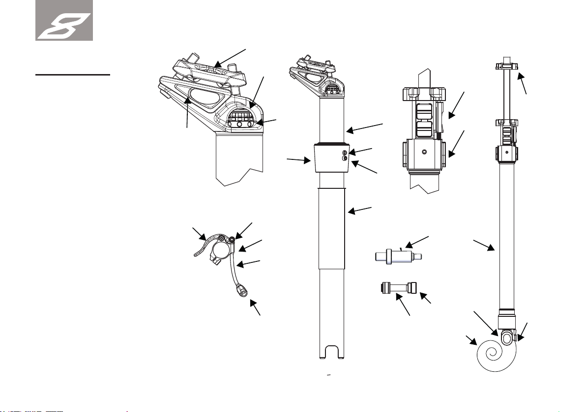
Part description
1 Eightpins Maintube
2 Eightpins Cartridge
3 Bushing
4 Outer sleeve
5 Fixing screw
6 Lubrication port
7 Flex aluminium cable housing
8 Remote lever
9 Cable clamping nut
10 Inline cable adjuster
11 End cap small
12 Special end cap or FlexChain
13 Valve adapter
14 Cable: Eightpins or Campagnolo
15 Postpin axle
16 Seat angle adjuster
17 Height adjuster
18 Seat clamp top
19 Seat clamp bottom
20 Release slider
21 Guiding inserts
22 Height adjusting clamp
23 Mounting interface
24 Adjusting ring

7
EIGHT
PINS
Compatibilities
The integrated Eightpins variable seatpost is exclusively designed for frames with a Postpin interface. One can not retrofi t this interface to a bicycle
frame. Refer to your local bike shop in case you are in doubt.
Attention: Eightpins decisively advices its customers not to modify a frame in any way, as this can weaken the
frame, cause crashes and lead to severe injuries including death.
Eightpin‘s seatposts are divided into two different size schemes. There is a size scheme with 4 sizes: S, M, L and XL and a size scheme with 6
sizes: XS, S, M, L, XL, XXL. The size to use depends entirely on the frame size.
Use only Eightpins cartridges of the correct size for the appropriate frame size. (Example: 6X-L cartridge fi ts into a frame with 6-fold size scheme
with the size L)
The bushing tube length is selected so that it corresponds to the minimum insertion depth of the seattube in the frame. All bending forces are trans-
ferred to the frame via the bushing tube. When assembling or exchanging the bushing tube, the correct length must be used.
The respective length can be found in the table under the column bushing tube.
It is also important to pay attention to the compatibility of the seatpost tube lengths. The table contains all possible combi-
nations. The corresponding adjustment ranges can also be found in the table. The values refer to the distance between the
bottom bracket and the upper edge of the saddle. Included is a saddle with a height of 4cm.
ATTENTION! Only the intended and compatible seat post sizes, strokes and bushing tube
lengths specifi ed by the bike manufacturer may be used.
HP
LP

8
EIGHT
PINS

9
EIGHT
PINS
Installation
Frame/seattube
Cable housing / bowden insallation
Install the cable housing in the frame before installing the seat post. Please follow the instructions of the frame manufacturer. The cable housing is
to be inserted into the seat tube until about 2 cm of it reach out of it. The second end of the housing – at the top of the frame – is to be cut depen-
ding on the frame size. The cable housing is pushed further out of the frame during assembly of the seat post by the length X. Observe the following
table when cutting the cable housing and shorten it to the desired length.
The frame must have a 5mm hole at the top of the seat tube to mount and fi x the outer sleeve. If this hole does not
exist, refer to the manual of the frame supplier to fi nd out how to drill this hole in the seat tube of the frame.
ca. 20mm
Länge X
length X
Länge X
length X

10
EIGHT
PINS
Endcap
Installation of the seatpost
There are two different types of end caps which can be fi tted to the end of the outer cable at the seattube side. Left
picture shows the special end cap of Eightpins. This is mainly used in non-e-bikes. The right picture shows the Lukon
Flex chain end cap version which is mainly used for e-bikes. This ersion allows a cable routing with very narrow radius
around the interface. This is needed if the space between electric motor and seat post is tight and limited.
Insert the cable into the ca-
ble housing until it reaches
out of it again at the top of
the frame.
Push the bushing tube
and the outer sleeve to the
lower end of the seatpost.
Hang the cable housing on
the cable housing coun-
terpart at the Postpin moun-
ting unit at the lower end of
the Eightpins
capsule.
Tension the cable at the
front end of the cable
housing and carefully insert
the seatpost into the seat
tube of the
frame.

11
EIGHT
PINS
we The bushing must be carefully inserted into the frame.
Attention! If mounting in aluminum frames with non-anodised inner walls, lubricate the
bushing tube with grease before installation.
Attention! When mounting in carbon frames, never treat parts with friction paste
Carefully press the outer sleeve onto the seat tube by hand. Press on until the outer sleeve hits the stop.
While pushing the seatpost downwards, pull the cable in order to have it under slight
pressure at all times and that the outer cable does not slip out of the postpin interface
socket.
Insert the seatpost until you can see the Postpin mounting unit through the hole of
the Postpin interface. You must be able to fully see the slot of the mounting interface
through the hole. Insert the Postpin axle into the postpin hole of the postpin interface
and tighten it loosely with a 5mm hex key.

12
EIGHT
PINS
Tighten the postpin
with a torque wrench with
8 Nm.
Rotate the outer sleeve by
rotation so that the moun-
ting hole of the outer sleeve
coincides with the mounting
hole on the frame.
Screw the M5 mounting
screw of the outer sleeve
into the outer sleeve with a
3mm Allen key.
Attention! The screw must be easy to screw into the outer sleeve. If this is not the case, perhaps the hole in the
frame does not coincide with the mounting hole of the outer sleeve. The frame can be squeezed or damaged
Assembly of the remote lever
The cable system of the Eightpins seatpost consists of a common cable housing with a Steel core and a short, more fl exible cable housing with
an Aluminum core directly at the remote lever. The cable system right at the remote lever consists of a 10 cm Aluminum cable housing, a specifi c
cable tension adjusetr and a specifi c end cap for the remote lever featuring a reduced outer diameter. The specifi c end cap is installed at the one
end of the cable housing, the cable tension adjuster at the other end. The cable tension adjuster is installed so that the side with the 4 mm label is
connected with the Aluminum cable housing. The second end is attached to the steel cable housing that reaches out of the frame..
Note: Initially, put the cable tension adjuster into the minimum cable length position.

13
EIGHT
PINS
Install the remote lever between the grip and the brake lever and tighten its screw with 2.5 Nm.
Note: The lever can be used with 2-speed drivetrain gear levers and without. Make sure the Eightpins
remote lever does not interfere with the gear lever. Further turn it upwards, in order to avoid this.
Before the cable is attached to it, pull it fi rmly until the click mechanics is fully open. You can hear a slight click from
the inside of the seat tube. When releasing again, you will hear another click. This process is important to confi rm
that all components of the cable system sit tightly.
cable housing
bowden cable
cable adjuster
ex aluminium
cable housing
end cap small
clamping nut
14
EIGHT
PINS
If the cable housing can be pushed into the frame in any way during the check, it has been detached from the cable
housing counterpart at the Postpin mounting unit. Take out the seatpost and attach the outer sleeve in the counter
part of the mounting interface
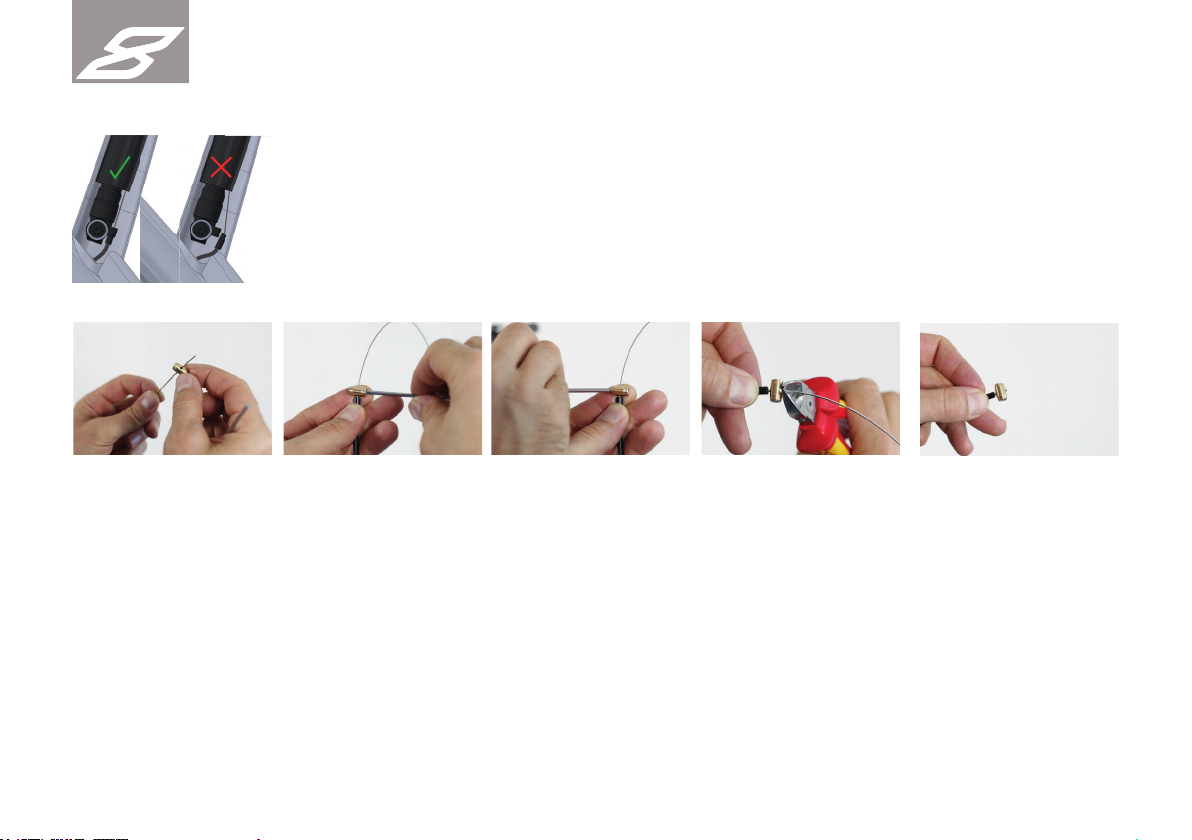
Pull the cable clamp of the
remote lever over the cable
and guide it all the way to
the cable housing.
Very slightly tighten its
screw with a 3mm Allen key
on both sides so it can still.
be moved. Position it about
2mm away from the cable
housing.
Cut the cable directly at the
cable clamp. Pull it away
from the cable housing a
little bit in order to have
the end of the cable itself
disappear within it.

15
EIGHT
PINS
Attention! In order to avoid injuries, the cable needs to be pulled into the cable clamp hiding any type of cable bits
sticking out of it.
3mm
The distance between cab-
le clamp and cable housing
should still not exceed 3
mm.
Tighten the two screws of
the cable clamp simul-
taneously with a torque
wrench with 5 Nm.
5mm
5mm
Hold the Aluminum cable
housing with your hand.
With the other hand, pull
the cable in order to open
the click mechanism.
With this pretension, fi rst
hang the Aluminum cable
housing with the end cap
on the remote lever.
In the last step, the end
cap can be hanged on the
remote lever.
16
EIGHT
PINS
Press the lever in order to
control the function of the
mechanics.
If the tension is too low, you
will feel a low resistance at
fi rst before you then feel a
higher one.
Adjust the cable tension
with the cable tension ad-
juster in order to minimize
the free travel.
The cable tension is adjusted correctly
if you feel the higher resistance at the
last 2 to 3 mm pushing the lever. If the
tension is too high, the click mechanics
does not open and the seatpost can not
be fi xated.
If the tension is too high, the click mechanics does not open and the seatpost can not be fi xated. In that case loosen the cable
tension again until the locking mechanic works again.
17
EIGHT
PINS
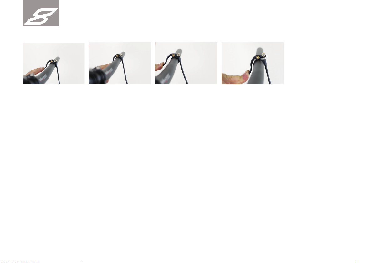
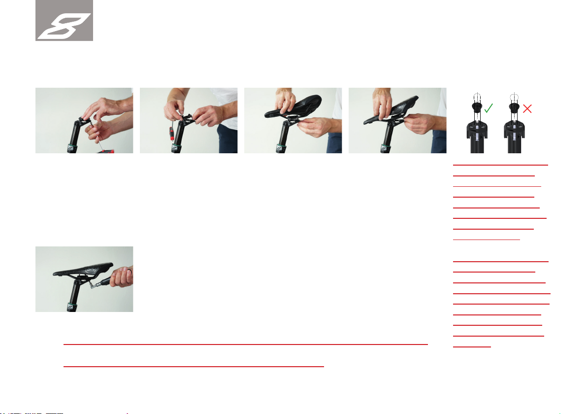
Mounting the saddle
Attention: The back screw of the seat post head must not be tightened with more than
8 Nm, as it might break and lead to an increased risk of injury.
Loosen and remove the
rear screw of the saddle
clamp.
With the front screw, adjust the saddle angle. Turning it clockwise, the tip
of the saddle moves upwards; turning it anticlockwise, the tip of the saddle
moves downwards.
With an 5mm bit and a torque wrench, tighten the rear screw with 8 Nm.
Note: Altering the saddle angle, you always need to loosen the
rear screw fi rst.
With the saddle angle ad-
justment screw, loosen the
front screw.
Insert the top saddle plate
and position it over the
saddle rails.
Have the saddle lay on
the sockets for the saddle
rails and insert the back
screw for the saddle fi xation
again.
ATTENTION: The nuts
which are installed
in the top seatclamp
have two small fl at
areas which have to
be aligned in the long
hole parallel to the
riding direction.
ATTENTION: If the nut
are not aligned cor-
rectly and the screws
get tightened, the nuts
getdamaged and can´t
move anymore. This
can cause a crack of
the screws. High risk
of injury!

18
EIGHT
PINS
Saddle angle
Alignment of the saddle
The Eightpins NGS2 seatpost has a overload clutch which gives way in case of a fall and lets the saddle turn sideways. This is only
roughly set in the assembly. If, after assembly, the saddle is slightly to the side, it can be easily turned to the desired position. The
required force is about 45Nm.
With an 5mm bit and a torque wrench, tighten the rear screw with 8 Nm.
Attention: The back screw of the seat post head must not be tightened with more than 8 Nm,
as it might break and lead to an increased risk of injury.
With the front screw, adjust the saddle angle. Turning it clockwise, the tip of the saddle moves upwards; turning it anti-
clockwise, the tip of the saddle moves downwards.
Loosen the rear fi xing screw on the seat post head with a 5 mm Allen key.
Note! To change the saddle angle, fi rst loosen the rear saddle clamp screw in order to be able to
adjust the saddle with the saddle angle adjuster.

19
EIGHT
PINS
Manual
Using the seatpost
In order to lower the seatpost, push the remote lever at the handlebar and push down the seatpost. In order to keep the new saddle position,
release the remote lever. Extending the seatpost again, you need to push the remote lever and without counterforce let it fi nd its original height. The
Eightpins variable seatpost works fully mechanically and features click notches every 6 mm.
Attention: The remote lever must not be pushed if the bike hangs on the saddle.
Aligning the seatpost / Operating the overload clutch
The Eightpins seatpost features an overload rotation clutch. This allows for the seatpost to turn away in case of a crash and thus prevents both the
saddle and the seatpost from damages. If this has happened, the saddle can simply be brought back into place by turning it. If the breakaway force
is too low, it can be increased (refer to the chapter “Service”).
Attention: the saddle can be turned to the left or right with a maximum angle of 90°. If it is turned
further, it will be damaged severely.!
90Grad über 90Grad

20
EIGHT
PINS
Seat height adjustment top position
Refer to the chapter “Seat height adjustment”.
Adjustment of the saddle angle
Refer to the chapter “Installation of the saddle”.
Before every single ride
Check the following functions of the seatpost before every ride:
- In both rotation directions, there should be no play noticeable.
- The seatpost should not have more play than 2 – 3 mm to the front or back. If the clearance is bigger, check the minimum insert length and
whether the bushing tube is ok (also refer to the chapter “Service”).
- The saddle must not have any play, the back screw is to be tightened with 8 Nm
- The mechanics to lower the seatpost has to run smoothly and without friction. In case you notice friction, the bushing tube has to be greased (see
chapter service). If the lubrication of the seatpost does not improve, there may be an adjustment error of the adjusting ring in the frame. Other rea-
sons can also be a squeezed bushing tube or the cable in the cartridge is located next to the guiding insert.
- The remote lever is to run smoothly. The tension cable should be adjusted correctly which you can do with the cable
tension adjuster (refer to the chapter: “remote mounting”). The lever automatically is to go back into place when released.
If this is not the case, you presumably need to replace the cable.
- Check the function of the click mechanism in the top position, in the bottom position and in an intermediate positions.
If you hear a grinding noise, the cable tension needs to be controlled.
Table of contents
Other Eightpins Bicycle Accessories manuals


