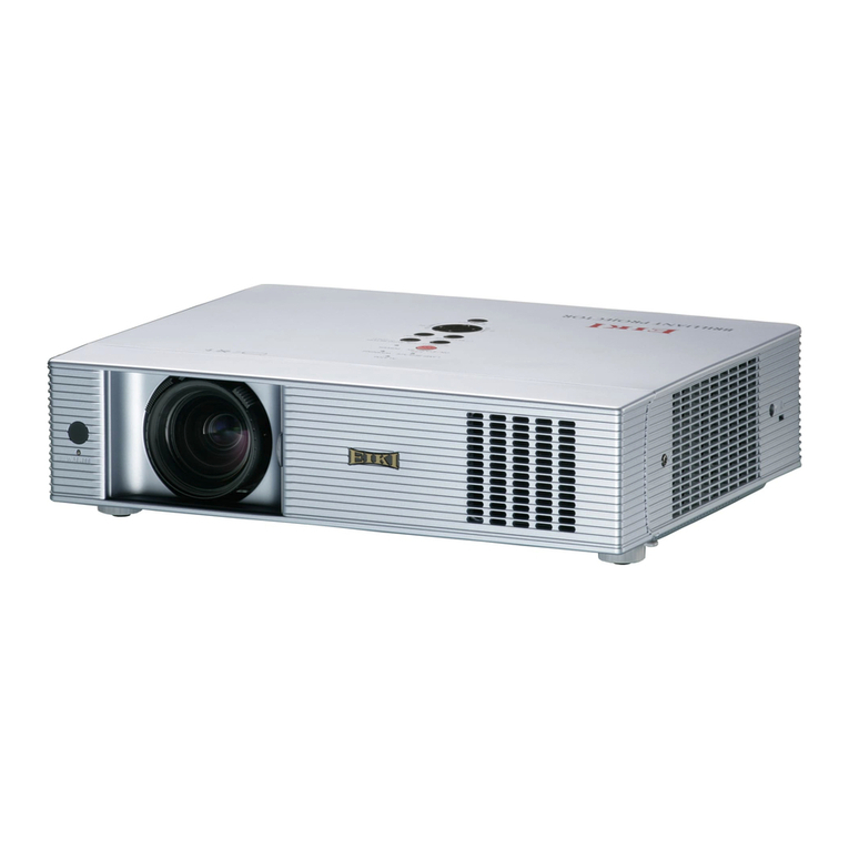
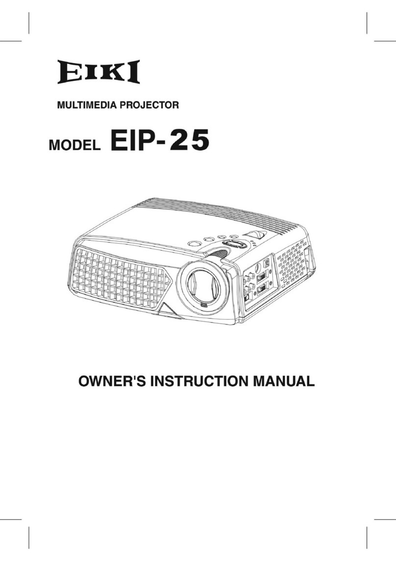
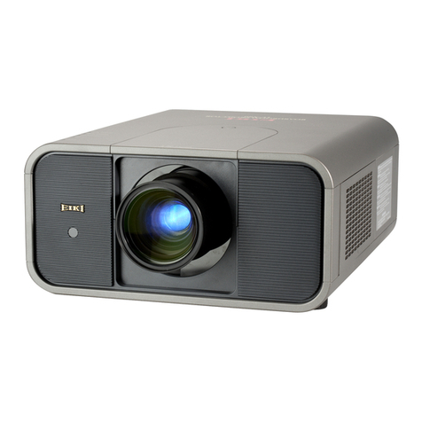
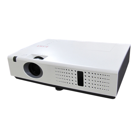
Eiki EIP-25 User manual

SERVICE MANUAL Multimedia Projector Model No. EIP-25
FOREWORD
For your convenience, all service parts, identified in this manual are available through Eiki’s normal distribution
channels. In addition to service part number, the generic descriptions have been give, where possible, to allow
your service technicians to substitute equivalent components which might be available from other sources.
All orders for service parts will be honored. However, in instances where generic components are considered to
be available from several common sources, as would be the case with an industry standard fuse, resistor, or
semiconductor, it may be more economical and expeditious to purchase the part locally.
Chassis No.: 4121012021
Issue Date: 2004/3/17
Version: B.5

EIP-25 Projector CHASSIS NO. 4121012021
1
█Contents
█Safety Instructions _____________________________________________________ 2
█Specifications_________________________________________________________ 3
█Adjustments after Parts Replacement ______________________________________ 4
█Circuit Protections _____________________________________________________ 5
●Fuse ________________________________________________________ 5
●Thermal switch ________________________________________________ 5
●Interlock switch ________________________________________________ 5
●Warning temperature ___________________________________________ 5
█Mechanical Disassemblies ______________________________________________ 6
█Optical Parts Disassemblies _____________________________________________ 18
█Lamp Replacement ____________________________________________________ 23
█Cleaning ____________________________________________________________ 24
█Optical Adjustment_____________________________________________________ 25
█Electrical Adjustment ___________________________________________________ 26
█Block Diagrams and Waveform ___________________________________________ 28
█Troubleshooting _______________________________________________________ 51
●Components Allocation __________________________________________ 51
●Power on Problems _____________________________________________ 52
●Image Quality Problems _________________________________________ 53
●Power Problems _______________________________________________ 54
●Remote Controller Problems ______________________________________ 54
●OSD Problems ________________________________________________ 54
█Upgrading OSD Software _______________________________________________ 55
█Power Supply Connector Pinouts _________________________________________ 57
█Service Parts List______________________________________________________ 58
●Product tree diagram____________________________________________ 58
●Parts List _____________________________________________________ 59
Drawings & Diagrams _____________________________________________________ 84

EIP-25 Projector CHASSIS NO. 4121012021
2
█Safety Instructions
SAFETY PRECAUTIONS
WARNING:
The chassis of this projector is isolated (COLD) from AC line by using the converter transformer.
Primary side of the converter and lamp power supply unit circuit is connected to the AC line and it
is hot, which hot circuit is identified with the line ( ) in the schematic diagram. For continued
product safety and protection of personnel injury, servicing should be made with qualified
personnel.
The following precautions must be observed.
1: An isolation transformer should be connected
in the power line between the projector and
the AC line before any service is performed
on the projector.
2: Comply with all caution and safety-related
notes pro vided on the cabinet back, cabinet
bottom, inside the cabinet or on the chassis.
3: When replacing a chassis in the cabinet,
always be certain that all the protective
devices are installed properly, such as,
control knobs, adjustment covers or shields,
barriers, etc.
DO NOT OPERATE THIS PROJECTOR
WITHOUT THE PROTECTIVE SHIELD IN
POSITION AND PROPERLY SECURED.
4: Before replacing the cabinet cover,
thoroughly inspect the inside of the cabinet to
see that no stray parts or tools have been left
inside.
Before returning any projector to the customer,
the service personnel must be sure it is
completely safe to operate without danger of
electric shock.
SERVICE PERSONNEL WARNING
Eye damage may result from directly viewing the light produced by the Lamp used in this
equipment. Always turn off Lamp before opening cover. The Ultraviolet radiation eye protection
required during this servicing. Never turn the power on without the lamp to avoid electric shock or
damage of the devices since the stabilizer generates high voltages (15kV - 25kV) at its starts.
Since the lamp is very high temperature during units operation replacement of the lamp should
be done at least 45 minutes after the power has been turned off, to allow the lamp cool-off.
DO NOT ATTEMPT TO SERVICING THE
REMOTE CONTROL UNIT.
Laser Beam may be leaked out when in disassemble the Unit.
As the laser Beam used in this Remote control unit is harmful
to the eyes.
EIP-25 Projector CHASSIS NO. 4121012021
3
█Specifications
Projection System DLP (Digital Light Processor)
Panel 0.7” DMD x 1/DDR
Native Resolution 1024x768
Resolutions Supported 640x480, 800x600,1024x768, and 1280x1024
Input Sources D-sub(RGB), D-sub(Y, Pb, Pr), Component RGB(Y, Cb,
Cr), RCA Video/Audio, S-video, PC Audio, IR
Output Sources D-sub(RGB), PC Audio
Video Compatibility NTSC/ PAL/ SDTV 480i
HDTV Support Compatible with 1080i, 720p, and 480p
Aspect Ratio 4:3, 16:9
Brightness 2500 LUMENS
Brightness Uniformity 80%
Contrast Ratio 1800:1
Number of Colors Full 16.2 million color palette
Color Coordinates x = 0.295 +/- .025, y = 0.315 +/- .025
Sync Range Horizontal: 15 to 100 kHz, Vertical: 50 to 100 Hz
Optical System Condenser Architecture
Lens Type Manual focus and manual zoom F: 28.0-33.6mm
Keystone Correction ±20 Degrees Electronically
Projection Distance 1.45 meter to 12.72 meter
Zoom Ratio 1.2:1
Projection Methods Front/Rear/Ceiling
Audio 2* 2.5 watts stereo speaker
Remote Control IR Remote Control with Laser Pointer and Mouse Control
Communications DDC2
Lamp Type OSRAM P-VIP 250W/1.3 E21.8
Lamp Life Average life greater than 1500 hours
Dimensions 330mm x 277 mm x 105 mm
Weight 3.7kg
Power Supply 100-240 VAC, 50-60Hz
Power Consumption 350 Watts Maximum
Audible Noise 34 dBA typical
●The specifications are subject to change without notice.
This symbol on the nameplate means the product is Listed by Underwriters
Laboratories Inc. It is designed and manufactured to meet rigid U.L. safety
standards against risk of fire, casualty and electrical hazards.

EIP-25 Projector CHASSIS NO. 4121012021
4
█Adjustments after parts replacement
A: Adjustment necessary C
C: Check necessary
Disassembly / Replaced Parts
DMD/Driver Board Main Board
Optical
Adjustments Mirror A
Color index
adjustment test C
C
Calibration C
C
Reset all
RGB_Analog C
C
Electrical
Adjustments
Reset all DVI C
C

EIP-25 Projector CHASSIS NO. 4121012021
5
█Circuit Protections
●Fuse
The fuse is located on the power supply
board. It can’t replace it alone. Please
replace power supply.
●Thermal switch
There is the thermal switch inside of the projector to prevent the internal temperature rising
abnormally. When the internal temperature reaches near 100°C, turn off the AC main power
supply automatically.
The thermal switch is not reset to normal automatically even if the internal temperature becomes
normal. Reset the thermal switch following procedure.
Check the resistance between terminals of thermal switch may be in operative.
How to reset the thermal switch
1. Remove cabinet top following to the “Mechanical Disassemblies”.
2. Press the reset button on the thermal switch.
●Interlock switch
The interlock switch cuts off the AC main power supply when the lamp cover is removed. After
opening the lamp cover for replacing the lamp ass’y, place the lamp cover correctly otherwise the
projector cannot turn off.
●Warning temperature
The projector will be automatically turned off when the internal temperature of the projector
exceeds the normal operating temperature, or the cooling fans stop, or the power supplies in the
projector are failed.
- If the TEMP LED indicator (red) is flashing, it may detect the abnormal temperature inside the
projector. Check the following possible causes and wait until the WARNING TEMP indicator
flashing stops, and then try to turn on the projector.
- If both of the TEMP WARNING (red) and READY (green) indicators are flashing at the same
time, It may defect the cooling fans and power supply circuits. Check fan operation and power
supply lines referring to the chapter “Power supply & protection circuit” in the Chassis Block
Diagram section.

EIP-25 Projector CHASSIS NO. 4121012021
6
█Mechanical Disassemblies
1. Cabinet top removal
(1) Remove 2 screw A (M3x 80), 2 screw B (M3x10), 1 screw C (M2.6x8) to take the cabinet top
assy upward off.
A
B
C
A
B
Screw A 7110230802
Screw B 7110430103
Screw C 7140226082

EIP-25 Projector CHASSIS NO. 4121012021
7
2. Focus ring AL removal
(1) Remove 3 screws A (M2x4) to take the Focus ring AL Off
Screw A 7110820043
Focus Ring AL
7535700006

EIP-25 Projector CHASSIS NO. 4121012021
8
3. Front panel and Adjuster leg assy removal
(1) Remove 4 screws A (T3x6) to take the adjuster leg assy off.
(2) Remove 3 screws B (T3x6), C (m3x10) take the Front panel assy off
B
C
A
A A
A
C
C
Screw A 7140330063
Screw B 7140330063
Screw C 7110330103

EIP-25 Projector CHASSIS NO. 4121012021
9
4. I/O Board assy removal
(1) Pull the I/O Board assy upward. and disconnect the I/O board connector.
(2) Remove 4 screws A (T2.6x8), 6 screws B (hex #4-40UNC) to take the I/O Board off.
A
B
Screw A 7141226082
S
crew B with VGA/ DVI
connector
I/O BD
5175200001

EIP-25 Projector CHASSIS NO. 4121012021
10
5. Fan (80x80) assy removal
(1) Remove 1 screw A (T3x6), 1 screw B (M3x10) to take the Fan assy (80x80) off
(2) Take the 2 Fan w/rubber holder Off From the Grille assy.
(3) Take the 2 Fan (80x80) from Rubber holder.
A
B
Screw A 7140430062
Screw B 7110330103
FAN (white connector)
7537300009-0B
FAN (yellow connector)
7537300013-0B
Rubber holder 7535400006

EIP-25 Projector CHASSIS NO. 4121012021
11
6. Power Board .Ballast Board .Blower .AC Inlet w/sw. removal
(1) Remove 2 screw A (M2.5x6) and disconnect the lamp ballast socket.
(2) Remove 6 screws B (T3x6) to take the POWER assy off.
A
B
A
B
Screw A 7110625043
Screw B 7110330103
POWER SUPPLY BD
6896220011
BALLAST
6895000004
BLOWER 7537300011-0B

EIP-25 Projector CHASSIS NO. 4121012021
12
(3) Remove 4 screw C (M3x6) and take the Ballast Board off.
(4) Remove 4 screw C (M3x6) and take the Powert Board off.
(5) Remove 2 screw D (M3x22) and take the Blower off.
(6) Remove 1 screw E (M2x6) and take the thermal sw Board off.
C
C
D
E
D
C
C
C
C
Screw C 7110430062
Screw D 7110230223
Screw E 7110820043

EIP-25 Projector CHASSIS NO. 4121012021
13
7. Fan (70x70) assy removal
(1) Remove 3 screw A (T3x6) and take Fan (70x70) assy off.
(2) Remove 2 screws B (M3x22) to take the Fan (70x70) w/rubber holder off.
(3) Take the Fan (70x70) from Rubber holder.
B
A A
A B
Screw A 7140430062
Screw B 7110230252
Rubber holder 7535400007
FAN 7537300010-0B

EIP-25 Projector CHASSIS NO. 4121012021
14
8. Optical Unit removal (1)
(1) Remove 1 screw A (M3x6) to take the Lamp Cover off.
(2) Loosen 3 screw B (M2.5x6) to take the Lamp assy by pulling the handle.
A
B
B B
Screw A 7110630063
Screw B 7110625063
Lamp Cover
7532202002

EIP-25 Projector CHASSIS NO. 4121012021
15
9. Optical Unit removal (2)
(1) Remove 10 screw C (M2.6x8) to take the Optical unit upward off.
Screw C 7140226082
Thermal Switch
6853010500

EIP-25 Projector CHASSIS NO. 4121012021
16
10. Main Board removal
(1) Remove 4 screws A(T3x6) to take the Main Board upward off.
Screw A 7140430062
MAIN BD
5173300021

EIP-25 Projector CHASSIS NO. 4121012021
17
11. In lock sw Board and D-Sub jack assy removal
(1) Remove 1 screw A (T2x4) to take the Inlock sw Board.
(2) Remove 3 screws B (T3x6) to take the D-sub jack assy.
A
B
B
B
Screw A 7141220043
Screw B 7140430053

EIP-25 Projector CHASSIS NO. 4121012021
18
█Optical Parts Disassemblies
1. Lamp Door & Lamp assy removal
(1) Remove 1 screw A (M3x6) to take the Lamp Door off.
(2) Remove 3 screws B (M2.5x6) to take the Lamp assy off.
A
B
B B
Screw A 7110630063
Screw B 7110625063

EIP-25 Projector CHASSIS NO. 4121012021
19
2. Optical Engine Assy removal
(1) Remove the Cabinet top, Focus ring AL, Front panel. following to " Mechanical Disassemblies
Item 1.2.3.
(2) Remove 10 screws B (T2.6x8) to take the Optical Engine Assy off.
Screw B 7140226082
Other manuals for EIP-25
2
Table of contents
Other Eiki Projector manuals

Eiki
Eiki LC-X990 Setup guide

Eiki
Eiki LC-WGC500 User manual

Eiki
Eiki LC-SVGA870U Setup guide

Eiki
Eiki LC-XA20 User manual

Eiki
Eiki LC-SX6A User manual

Eiki
Eiki WB200 User manual

Eiki
Eiki Multimedia Projector LC-XG400 User manual

Eiki
Eiki LC-XBL20 User manual

Eiki
Eiki LC-SM4 User manual

Eiki
Eiki LC-XNB5MS User manual