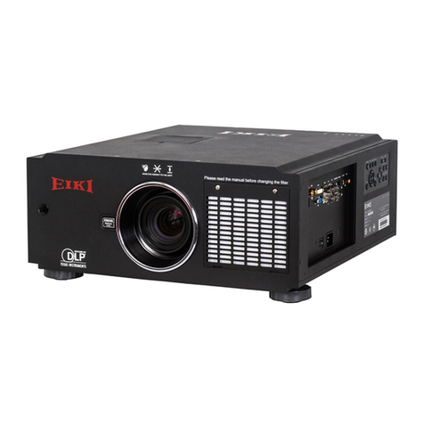
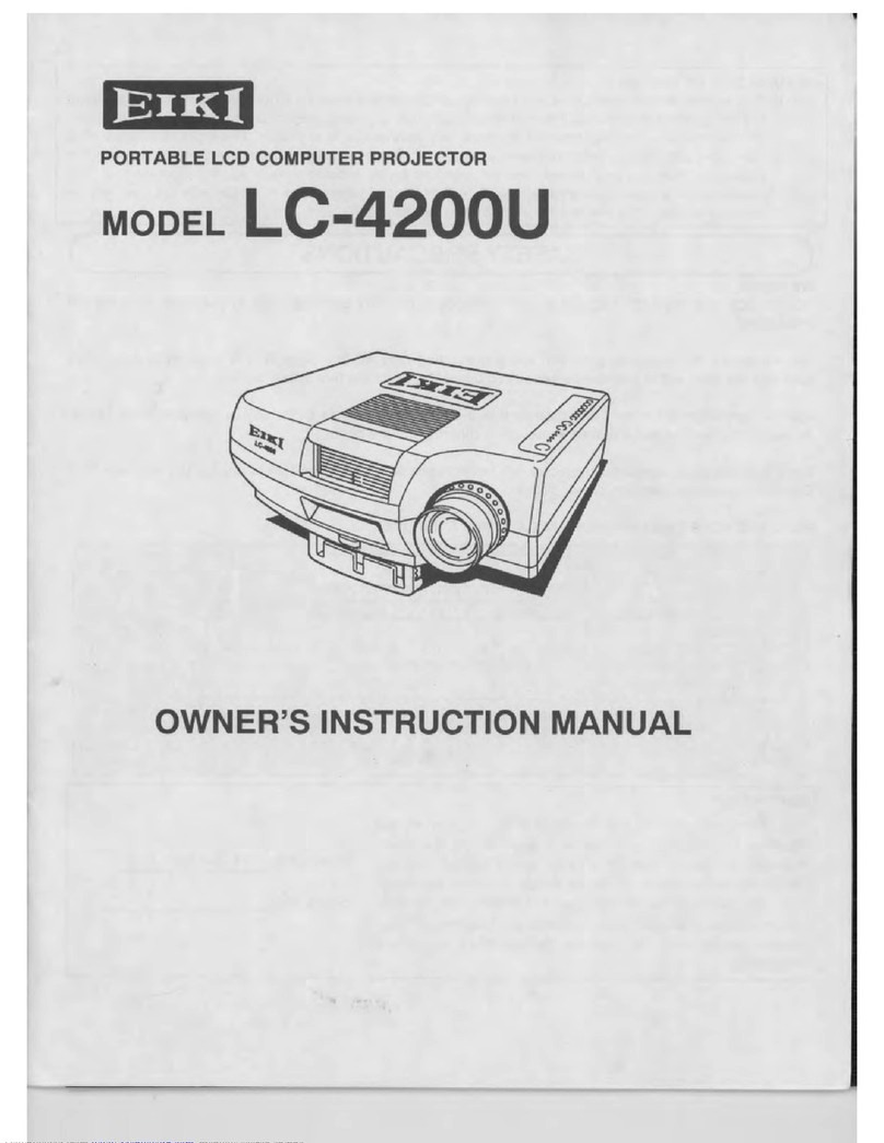
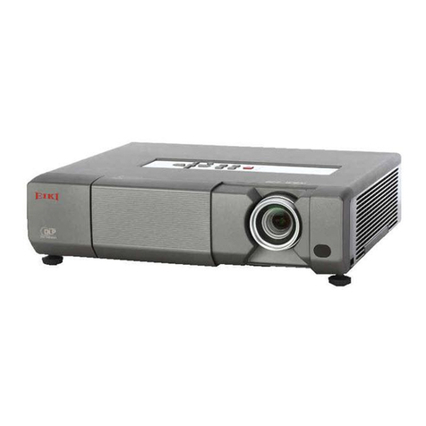
Eiki EIP-HDT30 User manual

* Projection lens is optional.
PRODUCT CODE
1 122 533 21 (KE2BL)
1 122 535 21 (LE2BL)
1 122 535 26 (LE2GL) REFERENCE NO. SM5111277-00
Multimedia Projector
SERVICE MANUAL
Model No. EIP-HDT30
U.S.A., Canada,
Europe, H.K
Give complete “Chassis No.” for parts
order or servicing, it is shown on the
rating sheet on the cabinet on the pro-
jector.
FOREWORD
For your convenience, all service parts, identified in this manual are available through Eiki’s normal distribution chan-
nels.
In addition to service part number, the generic descriptions have been given, where possible, to allow your service
technicians to substitute equivalent components which might be available from other sources.
All orders for service parts will be honored. However, in instances where generic components are considered to be
available from several common sources, as would be the case with an industry standard fuse, resistor, or semicon-
ductor, it may be more economical and expeditious to purchase the part locally.
ORIGINAL VERSION
Chassis No. KE2-HDT3000

-2-
Contents
SERVICE MANUAL ................................................... 1
Contents ........................................................................ 2
Safety Instructions......................................................... 3
Safety Precautions ..........................................................3
Product Safety Notice .....................................................3
Service Personnel Warning.............................................3
Specifications ................................................................ 4
Circuit Protections ......................................................... 5
Fuse.................................................................................5
Thermal switches (SW903, SW904) ...............................5
Mechanical sensor switches (SW902, SW1891).............6
Temperature sensors, wind sensors ...............................7
Power failure and fan lock detection ...............................8
Maintenance.................................................................. 9
Filter Instructions.............................................................9
Replacing the Filter Cartridge ....................................... 10
Resetting the Filter Counter .......................................... 11
Resetting the Scroll Counter ......................................... 11
Lamp Management ....................................................... 12
Lamp Replacement ....................................................... 13
Optional Color Wheel Installation.................................. 15
Cleaning the Optical Parts ............................................ 16
Security Function Notice ............................................. 17
Lens Mounting and Removing..................................... 18
Mechanical Disassembly............................................. 21
Mechanical disassembly flow chart...............................21
Mechanical disassembly ...............................................22
Adjustments................................................................. 37
Adjustments after Parts Replacement...........................37
Service Adjustment Menu Operation ............................38
Optical Adjustments .................................................... 39
Before Adjustment.........................................................39
Mirror adjustment ..........................................................40
Electrical Adjustment................................................... 41
Circuit Adjustments ....................................................... 41
Test Points and Locations .............................................45
Service Adjustment Data Table.....................................46
Chassis Description .................................................. 122
Chassis over view........................................................ 122
Boards Connection...................................................... 123
Troubleshooting......................................................... 124
No Picture.................................................................... 124
No Power..................................................................... 126
Power supply lines ......................................................130
Fan Control System..................................................... 131
Temperature Abnormality ............................................132
Power Lens and Shutter System and Abnormality...... 133
Lamp Abnormality ....................................................... 134
Power failure detection system ...................................135
Error information table................................................. 135
Power failure detection tree......................................... 136
Error History Log ......................................................... 137
Diagnosis of Power Failure with RS-232C port ...........138
Diagnosis procedure ................................................... 138
Indicators and Projector Condition.............................. 139
Serial Control............................................................. 142
Serial Control Interface ............................................... 142
Control Port Functions............................................... 144
IC Block Diagrams..................................................... 148
Parts Location Diagrams........................................... 156
Mechanical Parts List ................................................ 162
Electrical Parts List.................................................... 164
Diagrams & Drawings.................................................. A1
Parts description and reading in schematic diagram ..A2
Schematic Diagrams ...................................................A3
Printed Wiring Board Diagrams................................. A15
Pin description of diode, transistor and IC ................A23
Note on Soldering......................................................A24
-3-
Safety Instructions
WARNING:
The chassis of this projector is isolated (COLD) from AC line by using the converter transformer. Primary side
of the converter and lamp power supply unit circuit is connected to the AC line and it is hot, which hot circuit is
identified with the line ( ) in the schematic diagram. For continued product safety and protection of per-
sonnel injury, servicing should be made with qualified personnel.
The following precautions must be observed.
Safety Precautions
1: An isolation transformer should be connected in
the power line between the projector and the AC
line before any service is performed on the projec-
tor.
2: Comply with all caution and safety-related notes
provided on the cabinet back, cabinet bottom, inside
the cabinet or on the chassis.
3: When replacing a chassis in the cabinet, always
be certain that all the protective devices are
installed properly, such as, control knobs, adjust-
ment covers or shields, barriers, etc.
DO NOT OPERATE THIS PROJECTOR WITHOUT
THE PROTECTIVE SHIELD IN POSITION AND PR
OPERLY SECURED.
4: Before replacing the cabinet cover, thoroughly
inspect the inside of the cabinet to see that no stray
parts or tools have been left inside.
Before returning any projector to the customer, the
service personnel must be sure it is completely safe
to operate without danger of electric shock.
Service Personnel Warning
Eye damage may result from directly viewing the light produced by the Lamp used in this equipment. Always
turn off Lamp before opening cover. The Ultraviolet radiation eye protection required during this servicing.
Never turn the power on without the lamp to avoid electric-shock or damage of the devices since the stabilizer
generates high voltages (15kV - 25kV) at its starts.
Since the lamp is very high temperature during units operation replacement of the lamp should be done at least
45 minutes after the power has been turned off, to allow the lamp cool-off.
Product Safety Notice
Product safety should be considered when a component replacement is made in any area of the projector.
Components indicated by mark !in the parts list and the schematic diagram designate components in which
safety can be of special significance. It is, therefore, particularly recommended that the replacement of there
parts must be made by exactly the same parts.

-4-
Specifications
This symbol on the nameplate means the product is Listed by Underwriters
Laboratories Inc. It is designed and manufactured to meet rigid U.L. safety stan-
dards against risk of fire, casualty and electrical hazards.
Mechanical Information
Projector Type Multi-media Projector
Dimensions (W x H x D) 15.75” x 9.55” x 20.61” (400.0 mm x 242.5 mm x 523.5 mm)
Net Weight 43.21lbs (19.6 kg)
Feet Adjustment 0˚ to 5˚
DLP Chip
Projection System 0.95” Single DLP chip, High brightness color wheel x 2
Number of Pixels 2,073,600 pixels (1,920 x 1,080 dots)
Signal Compatibility
Color System
PAL, SECAM, NTSC, NTSC4.43, PAL-M, and PAL-N
High Definition TV Signal 480i, 480p, 575i, 575p, 720p, 1035i, 1080p, and 1080i
Input Scanning Frequency H-sync. 15 kHz–120 kHz, V-sync. 48 Hz–120 Hz
Optical Information
Projection Lamp 330 W UHP lamp x 2
Interface
Input 1 DVI-D Terminal (Digital), Mini D-Sub 15-pin Terminal (Analog), HDMI (v.1.3 with Deep Color)
Input 2 BNC Type x 5 (VIDEO/Y/G, B/Pb/Cb, R/Pr/Cr, H/HV and V), S-Video
Input 3 Vacant
Input 4 Vacant
Monitor Output Mini D-sub 15 pin
Other Jacks Serial port in (D-sub 9), Serial port out (D-sub 9), USB port, LAN port (RJ45) and Wired Remote
Jack
Power
Voltage and Power Consumption AC 100–120 V (10.0A Max. Ampere), 50/60 Hz (The U.S.A and Canada)
AC 100-240 V (10.0-5.0A Max. Ampere), 50/60 Hz (For other countries)
Operating Environment
Operating Temperature 41˚F–104˚F (5˚C–40˚C)
Storage Temperature 14˚F–140˚F (-10˚C–60˚C)
Remote Control
Battery AA or LR6 Type x 2
Operating Range 16.4’ (5 m/±30˚)
Dimensions 1.79” (W) x 1.03” (H) x 6.24” (D) (45.5 mm x 26.2 mm x 158.5 mm)
Net Weight 4.1 oz (117 g) (including batteries)
Accessories
Owner’s Manual (CD-ROM) Quick Reference Guide AC Power Cord
Remote Control and Batteries VGA Cable PIN Code Label
Fixing bracket for power cord Rich color reproduction color wheel x 2 Cable tie x 3
Real Color Manager Pro (CD-ROM)
●The specifications are subject to change without notice.

-5-
Fuse
Cover
Holder
This projector provides the following circuit protections to operate in safety. If the abnormality occurs inside the pro-
jector, it will automatically turn off by operating one of the following protection circuits.
Circuit Protections
A fuse is located at bottom of the projector. When the
POWER/LAMP indicators are not lighting, the fuse may be
opened. Check the fuse as following steps.
The fuse should be used with the following type;
Fuse Part No. : 323 028 4202
TYPE 15.0A 400V FUSE
SOC CORP. SHV14 15A N4
How to replace the fuse
1. Turn the projector upside down and remove the bottom
cover.
2. Remove the cover and fuse from fuse holder.
To install the fuse, take reversed step in the above.
There are the thermal switches (SW903 and SW904) inside of the projec-
tor to detect the internal temperature rising abnormally. When the internal
temperature reaches near 80˚C, the thermal switch opens to cut off the error
detection signal supplied to the system control part and then the projector will
set in the power failure mode.
The thermal switch will automatically return to normal condition when the
internal temperature becomes normal.
Thermostat
(SW903)
Thermostat
(SW904)
Fuse
Thermal switches (SW903, SW904)

-6-
Circuit Protections
Mechanical sensor switches (SW902, SW1891)
Filter cartridge switch
(SW1891)
Lamp cover switch
(SW902)
Filter cartridge
This projector provides 2 mechanical sensor switches, the one is for filter cartridge switch (SW1891) and the other
one is for lamp cover switch (SW902). The filter cartridge switch detects whether the filter cartridge is installed cor-
rectly.
The lamp cover switch detects whether the lamp cover is closed securely. If lamp cover is opened or not closed com-
pletely, the drive signal to the lamp circuit is cut off. After opening the lamp cover for replacing the lamp ass’y, place
the lamp cover correctly otherwise the projector cannot turn on.
POWER
LAMP
WARNING TEMP.
WARNING FILTER
SHUTTER
LAMP 1 REPLACE
LAMP 2 REPLACE
Indicators
LAMP indicator lights on
and other indicators blink.
CAUTION
DO NOT LEAVE THE PROJECTOR WITH THE AC POWER CORD
CONNECTED UNDER AN ABNORMAL CONDITION. IT MAY RE-
SULT IN FIRE OR ELECTRIC SHOCK.
The projector is shut down; and the LAMP indicator is lighting
and other indicators are blinking.
When the projector detects an abnormal condition (SW902, SW903, SW904
- opens), it will be automatically shut down to protect the inside of the projec-
tor and the LAMP indicator lights on and other indicators blink. In this case,
unplug the AC power cord and check that the filter cartridge and lamp cover
are installed securely, and the plug it, and turn on the projector once again to
verify operation. If the projector cannot be turned on and these indicators are
still lighting and blinking, unplug the AC power cord. See the troubleshooting
chapter.
The projector is turned on without installing the filter cartridge, and then the
filter cartridge is installed while the projector is on. The projector detects an
abnormal condition (SW1891 -closes), then it will also be automatically shut
down.

-7-
POWER
LAMP
WARNING TEMP.
WARNING FILTER
SHUTTER
LAMP 1 REPLACE
LAMP 2 REPLACE
The projector provides 3 temperature sensor ICs, 2 sensors on the Main board and 1 sensor on the Sensor board, 1
thermistor on the peltier device and 1 wind sensor on the intake duct. The sensor ICs monitor surrounding tempera-
ture of the optical parts, and surrounding temperature of the intake duct, and the wind sensor monitors airflow passed
through the air filter in the intake duct.
- Temperature sensor (IC8821) is on the main board for monitoring the surrounding temperature of DMD module.
- Temperature sensor (IC1381) is on the main board for monitoring the surrounding temperature of optical unit.
- Temperature sensor (IC8811) is on the sensor board for monitoring the surrounding temperature of the intake
duct.
- Thermistor sensor (TH901) is on the peltier device for monitoring the temperature.
- Wind sensor (S901) on the filter box.
Circuit Protections
IC8821
(Behind)
Temperature sensors, wind sensors
S901
Wind sensor
IC8811
The projector is shut down and the WARNING TEMP. indicator is
blinking red.
When the temperature inside the projector reaches a certain level, the projec-
tor will be automatically shut down to protect the inside of the projector. The
LAMP indicator turns red brighter and the WARNING TEMP indicator blinks
while the projector is being cooled down. When the projector has cooled
down enough (to its normal operating temperature), it can be turned on again
by pressing the ON/STAND-BY button.
✔Note:
• The WARNING TEMP. indicator continues to blink even after the temperature
inside the projector returns to normal. When the projector is turned on again, the
WARNING TEMP. indicator stops blinking.
Indicators
WARNING TEMP.
blinking red
IC1381
TH901
Thermistor

-8-
POWER
LAMP
WARNING TEMP.
WARNING FILTER
SHUTTER
LAMP 1 REPLACE
LAMP 2 REPLACE
The projector provides the detection circuits of the power failure and the fan lock. When the detection circuit detects
an error at the power supply line or at the fan operation circuit, the projector will turn into the standby mode to protect
the other circuits defective.
Circuit Protections
Power failure and fan lock detection
CAUTION
DO NOT LEAVE THE PROJECTOR WITH THE AC POWER CORD
CONNECTED UNDER AN ABNORMAL CONDITION. IT MAY RE-
SULT IN FIRE OR ELECTRIC SHOCK.
Indicators
The projector is shut down; and the LAMP indicator is lighting
and other indicators are blinking.
When the projector detects an abnormal condition (Power supply lines failure
or fans failure), it will be automatically shut down to protect the inside of the
projector and the LAMP indicator lights on and other indicators blink. In this
case, unplug the AC power cord and plug it, and then turn on the projector
once again to verify operation. If the projector cannot be turned on and these
indicators are still lighting and blinking, unplug the AC power cord. See the
troubleshooting chapter.
LAMP indicator lights on
and other indicators blink.

-9-
Maintenance
Filter Instructions
Filter prevents dust from accumulating on the optical elements inside the projector. Should the filter becomes
clogged with dust particles, it will reduce cooling fans’ effectiveness and may result in internal heat buildup and
adversely affect the life of the projector. This projector has an electrically operated filter which helps you to replace
the filter easily. The projector monitors the condition of the filter at all time and replaces a filter with a new one
automatically when it detects the clogging.
If the projector reaches a time set in the timer setting, a Filter re-
placement icon (Fig.1) appears on the screen and the WARNING
FILTER indicator on the top panel lights up. When you see this icon,
replace the filter as soon as possible. If the filter is out of scroll and
the projector reaches a time set in the timer setting, Fig. 2 appears
on the screen, indicating that the filter cartridge replacement is nec-
essary.
When the filter scroll is counted down to 1, the Last scroll icon
(Fig.3) appears on the screen, indicating that there is one scroll left
in the filter cartridge.
If the projector detects that the filter is clogged and no scroll is left
in the filter cartridge, a Filter cartridge replacement icon (Fig. 4) ap-
pears on the screen and the WARNING FILTER indicator on the top
panel lights up. When you see this icon, replace the filter cartridge
and reset the Filter counter and the Scroll counter.
When the filter is being scrolled by the remote control or the Fil-
ter control function in the setting menu, a Filter replacement icon
and “Please wait...” message (Fig.5) appear on the screen and the
WARNING FILTER indicator blinks slow (approx. 2 seconds ON, 2
seconds OFF).
The WARNING FILTER indicator blinks fast when the projector de-
tects an abnormal condition, the filter cartridge is not installed prop-
erly, or the filter scroll is not working properly.
Fig.1 Filter replacement icon
Fig.4 Filter cartridge replacement icon
Fig.3 Last scroll icon
✔Note:
• Fig.1, Fig.2, Fig.3 or Fig. 4 will not appear when the
Display function is set to “Off”, or during “Freeze”.
• The filter cannot be rewound.
• The filter can be scrolled 9 times since the filter cartridge
has 10 scrolls.
• The filter cartridge is disposable. Do not clean and reuse
the filter cartridge.
• Do not expose the filter cartridge to water or liquid, or it
may cause a breakdown.
• Replace the filter cartridge after all the scroll is used up. If
you replace the filter cartridge when there are some scrolls
left in the filter cartridge, the filter counter and the scroll
counter do not recognize the correct number of remaining
scrolls and the reset function cannot work properly. It may
cause a breakdown.
• The used part of the filter can be seen on the edge of the
Filter cartridge after scrolling the filter, but there is no prob-
lem for the use of the projector.
• Do not use the filter cartridge with other projector. The filter
counter and the scroll counter do not recognize the correct
number of remaining scrolls of the used filter cartridge and
the reset function cannot work properly. It may cause a
breakdown.
• Make sure that the projection lamps are turned off when
you are replacing the filter cartridge. If you replace the filter
cartridge when the projection lamps are turned on, the
projector will be shut down automatically for safety pur-
poses.
• Do not forget to reset the filter counter and the scroll coun-
ter in the setting menu after replacing the filter cartridge.
If you forget to reset the filter counter and the scroll coun-
ter, the projector cannot recognize the correct number of
remaining scrolls and it may cause a breakdown.
• When the projector is kept used for 3 minutes without get-
ting the filter cartridge replaced after the Fig.4 appears on
the screen, the projector is turned off automatically to pre-
vent the damage of optical components.
Fig.5 Filter replacement icon and
“Please wait...” message.
Fig.2

-10-
Turn off the projector, press the Main On/Off Switch to
Off and unplug the AC power cord from the AC outlet.
First, clean up the dust on the projector and around the
air vents.
1
2
Open the filter cover. (See the right figure.)
3
Put the new one back into the position and close the filter
cover. Make sure that the filter cartridge is properly and
fully inserted.
5
CAUTION
- Do not put anything into the air vents. Doing so
may result in malfunction of the projector.
- In the event of installation/replacement of the fil-
ter cartridge, turn off the projector, press the Main
On/Off Switch to Off and unplug the AC power
cord from the AC outlet.
4
Reset the filter counter and the scroll counter.
6
Replacing the Filter Cartridge
Pull out the filter cartridge. When taking out the filter
cartridge, put your finger on the filter cartridge's tab and
then pull.
RECOMMENDATION
We recommend avoiding dusty/smoky environments when
operating the projector. Usage in these environments may
cause a poor image quality.
When using the projector under dusty or smoky conditions, dust
may accumulate on a lens, or optical elements inside the projector.
Such condition may degrade the quality of the projected image.
When the symptoms above are noticed, contact your authorized
dealer or service station for proper cleaning.
ORDER REPLACEMENT FILTER CARTRIDGE
Service Parts No. : 610 350 7811
Connect the AC power cord to the projector and turn on
the projector.
7
Maintenance
Filter cover
Filter cartridge
Tab

-11-
Be sure to reset the Scroll counter after replacing the filter
cartridge.
Press the MENU button to display the On-Screen Menu.
Use the Point 7 8 buttons to move the red frame pointer
to the Setting Menu icon.
Use the Point ed buttons to move the red frame pointer
to Filter counter and then press the SELECT button. A
dialog box appears showing the Used time option and
the Scrolls remaining option. Use the Point ed buttons
to select Scroll(s) remaining.
1
2
Resetting the Scroll Counter
Scroll counter
Another confirmation dialog box appears, select [Yes] to
reset the Scroll counter.
3Scroll(s) remaining shows the number of the remaining
scrolls and the Reset option. Select Reset and the “Scroll
counter Reset?” appears. Select [Yes] to continue.
4
Be sure to reset the Filter counter after replacing the filter
cartridge.
Press the MENU button to display the On-Screen Menu.
Use the Point 7 8 buttons to move the red frame pointer
to the Setting Menu icon.
Use the Point ed buttons to move the red frame pointer
to Filter counter and then press the SELECT button. A
dialog box appears showing the Used time option and
the Scrolls remaining option. Use the Point ed buttons
to select Used time.
1
2
Resetting the Filter Counter
Filter counter
Select Reset and the “Filter
counter Reset?” appears.
Select [Yes],
then another
confirmation
box appears.
Select [Yes] again to reset
the Filter counter.
Another confirmation dialog box appears, select [Yes] to
reset the Filter counter.
3Used time shows the total accumulated time of the filter
use, a timer setting option, and the Reset option. Select
Reset and the “Filter counter Reset?” appears. Select
[Yes] to continue.
4
Select “Used time” and the dia-
logue box below appears.
Select “Scrolls remaining” and
the dialogue box below appears.
Select Reset and the “Scroll
counter Reset?” appears.
Select [Yes],
then another
confirmation
box appears.
Select [Yes] again to reset
the Scroll counter.
Maintenance

-12-
Maintenance
Lamp Management
This Projector is equipped with 2 Projection Lamps to ensure brighter image and those lamps are controlled by the
Lamp Management Function. The Lamp Management Function detects the status of lamps and shows the status
on screen or on the LAMP 1/2 REPLACE indicators. This function also automatically controls the Lamp Mode when
any of lamps is out for the end of life or malfunctions.
Projection Lamp lights normally.
Lamp 1/2 Replace Indicators
The LAMP 1/2 REPLACE indicators light orange when any of Projection Lamps is nearing its end, and flash when
any of them becomes out. Check the number of lamp on the Lamp Status Display or the LAMP 1/2 REPLACE
indicators and replace the lamp.
Yellow Lamp
Dim Lamp
X Mark on Lamp
Red Lamp
Projection Lamp is turned off.
Projection Lamp is nearing its end. When the image be-
comes darker or the color becomes unnatural, replace
lamp. (LAMP 1/2 REPLACE indicator lights orange.)
(LAMP 1/2 REPLACE indicator flashes orange.)
Projection lamp is defective or fails to be turned on. Re-
start the projector on, and make sure lamp is on. If this
mark still appears, replace lamp corresponding with num-
ber marked X.
LAMP STATUS
DISPLAY
Lamp Mode Changeover
The Lamp Management Function automatically changes the lighting lamp (Lamp Mode) by detecting the status of lamp. When
either of the 2 lamps is out, the projector operates with 1 lamp. The Lamp Mode can be switched to 2 lamps or 1 lamp manually.
Refer to the SETTING section on page 51.
2 LAMP MODE 1 LAMP MODE
When Lamp 2 is burnt out.
Lamp Status Display
The Lamp Status Display appears on screen when the projector is turned on or the input position (input 1, input 2,
Input 3 or input 4) is switched. This shows the status of each lamp as; ON, OFF, NEAR END, or OUT. Refer to the
following for each status.
Lamp status
When Lamp 1 is burnt out.
LAMP 1/2 REPLACE
INDICATORS

-13-
Check the number of lamp to be replaced on the Lamp
Status Display.
Loosen a screw on the Lamp Cover. Slide and open
the Lamp Cover until it makes a clicking sound. (See
the right figure.)
1
3
Loosen two screws and pull out the Lamp to be re-
placed by grasping handle.
4
Turn off the projector, press the Main On/Off Switch to
Off and unplug the AC power cord from the AC outlet.
Let the projector cool for at least 45 minutes.
2
Replace the Lamp with a new one and tighten two
screws. Make sure the Lamp is set properly.
6
Follow these steps to replace the lamp.
Put the Lamp Cover back and tighten a screw.
5
SCREW
LAMP
COVER
Make sure which number of lamp needs to be
replaced on Lamp Status Display.
Figure shows case of replacing LAMP 1.
LAMP 2
NOTES ON LAMP REPLACEMENT
To maintain quality of picture (better balance of color and brightness in entire screen), we recommend replacing both
2 lamps at a time.
Lamp Replacement
For continued safety, replace with a lamp assembly of
the same type.
Do not drop the lamp assembly or touch a glass bulb!
The glass can shatter and may cause injury.
Allow the projector to cool, for at least 45 minutes be-
fore you open Lamp Cover. The inside of the projec-
tor can become very hot.
CAUTION
TURN OFF THE UV LAMP BEFORE OPEN-
ING THE LAMP COVER.
WARNING:
When the projection lamp of the projector reaches its end of life, the Lamp replacement icon appears on the screen
and LAMP 1/2 REPLACE indicator lights orange. Replace the lamp with a new one promptly. The timing when the
LAMP 1/2 REPLACE indicators should light is depending on the lamp mode.
Indicators
Lamp replacement icon
✔Note:
•The Lamp replacement icon will not appear when the
Display function is set to “Off”, or during “Freeze”.
Maintenance
LAMP 1
SCREWS
ORDER REPLACEMENT LAMP
Replacement Lamp Type No. : POA-LMP145
Service Parts No. : 610 350 6814
POWER
LAMP
WARNING TEMP.
WARNING FILTER
SHUTTER
LAMP 1 REPLACE
LAMP 2 REPLACE
LAMP 1 / 2 REPLACE indicators

-14-
The LAMP REPLACE indicator will light yellow when the total lamp used time (Corresponding value) reaches 3,000.
The total lamp used time is calculated by using the below expression.
Total lamp used time (Corresponding value) = Teco + (Tnormal x 1.5)
Teco: used time in the Eco1 and Eco2 mode
Tnormal : used time in the Normal mode and Auto mode
You can check the lamp used time following to the below procedure.
1Press and hold the ON/STAND-BY button on the projector or remote control for more than 20 seconds.
2The projector used time and lamp used time will be displayed on the screen briefly as follows.
Counter
Projector 500H
Lamp Lamp1 Lamp2
Normal 200H 200 H
Eco 300H 300 H
Corresponding value 600H 600 H
Projector used time
Maintenance
Checking the projector used time and lamp used time
Lamp 2 Total lamp used time
Lamp 1 Total lamp used time
Lamp
control Normal Eco 1 Eco 2
Normal ✔
Eco ✔ ✔
Lamp used time table in the Lamp
control - Lamp mode
If the non-standard lamp is used, the warning and confirmation messages will appear on the screen every startup.
Some of the functions are limited when the non-standard lamp is used in spite of the warning.
Warning Message on the non-standard lamp used
Since the lamp is not standard,
projector failed to read lamp data.
Continue to use this lamp?
Yes
No

-15-
Optional Color Wheel Installation
The projector comes with the high brightness color wheels in-
stalled. Additional rich color reproduction color wheels are sup-
plied. To replace the color wheels, refer to the following steps.
✔Note:
•
Wait until the lamp house and the color wheel cool off.
•
Make sure to install the same type of two color wheels at the same
time. When different types of color wheels are installed, ‘Non-
matching color wheels!‘ message appears on the screen.
Allow the projector to cool, for at least 45 minutes before you open
Lamp Cover. The inside of the projector can become very hot.
Loosen a screw on the Lamp Cover. Slide and open the
Lamp Cover until it makes a clicking sound. (See the right
figure.)
1
3Loosen three screws and pull out the color wheel to be
replaced by grasping handle.
4
Turn off the projector, press the Main On/Off Switch to Off
and unplug the AC power cord from the AC outlet. Let the
projector cool for at least 45 minutes.
2
Replace the color wheel with a new one and tighten three
screws. Make sure the color wheels are set properly.
Put the Lamp Cover back and tighten a screw.
5
SCREW
LAMP
COVER
SCREWS
COLOR WHEELS
Maintenance

-16-
Cleaning the Optical Parts
Cleaning with air spray
Remove the cabinet top following to “Mechanical Disassembly”. Clean up the optical parts, color wheel, lens by using
the air spray from the cabinet top opening.
Caution:
The optical components may have a crack or spot when you use the air spray directly to the optical components
while they are in the state of hot. Use a commercial (inert gas) air spray designed for cleaning camera and computer
equipment. Use a resin-based nozzle only. Be very careful not to damage optical parts with the nozzle tip. Never
use any kind of cleanser on the unit. Also, never use abrasive materials on the unit as this may cause irreparable
damage.
Disassembly Cleaning
Disassembly cleaning method should only be performed when the unit is considerable dirty and cannot be suffi-
ciently cleaned by air spraying alone.
Be sure to readjust the optical system after performing disassembly cleaning.
Remove the mechanical parts following to “Mechanical Disassembly”. Clean the optical parts with a soft cloth. Clean
extremely dirty areas using a cloth moistened with alcohol.
Caution
The surface of the optical components consists of multiple dielectric layers with varying degrees of refraction. Never
use organic solvents (thinner, etc.) or any kind of cleanser on these components.
Cleaning the Color Wheel
- The color wheel is made of thin glass. Be very careful when handing the color wheel.
- In case of fingerprints, etc. on the surface, gently wipe with a Cleaning Cloth for optical parts that contains a small
amount of non-abrasive camera lens cleaner to clean the surface.
- Do not use detergents as this could cause peeling of the color filter.
Cleaning the DMD / Prism
- The Prism and DMD surface are glasses and can be cleaned. However, avoid scratches as these can have a direct
influence on the image.
1. Use a commercial (inert gas) air spray designed for cleaning camera and computer equipment to clean the sur-
face. If this does not remove, take next step.
2. Gently wipe the surface with a Cleaning Cloth for optical parts in one direction. Always use a new section of
the Cleaning Cloth. Using the same section of the Cloth has the potential of dragging particles and or adding
contaminant to the glass surface which may scratch the glass.
- Do not use absolute alcohol or other substances that could leave streaks after drying.
Cleaning the Reflecting Mirror
- Be careful not to touch the reflecting mirror. Touching it directly with the hands may cause reducing the burnish-
ing.
- Do not clean other than with air.
After long periods of use, dust and other particles will accumulate on the optical parts, DMD module, mirror, color
wheel, lens etc., causing the picture to darken or color to blur. If this occurs, clean the inside of optical unit.
Remove dust and other particles using air spray. If dirt cannot be removed by air spray, disassemble and clean
the optical unit. Before taking the cleaning, turn off the projector and allow the projector to cool for more than 45
minutes.
Maintenance

-17-
This projector provides security functions such as "Key lock", "PIN code lock" and "Logo PIN code lock". When the
projector has set these security function on, you are required to enter correct PIN code to use the projector. If you
do not know the correct PIN code to the projector, the projector can no longer be operated or started. In this case,
you must reset those function first according to the resetting procedure described below and then check up on the
projector.
Security Function Notice
Resetting procedure
1Turn off the projector with the Main switch.
2Press and hold the SELECT button on the projector and then turn on the projector with the Mains switch.
Keep pressing the SELECT button for more than 10 seconds.
This is complete the resetting of the security function. The PIN code lock and Logo PIN code lock are reset
as the initial PIN code at the factory and the Key lock function is disabled.
Please refer to the owner's manual for further information of the security functions.
Function Description
Key lock
Locks operation of the side control or the remote con-
trol.
If the Key lock is enabled with side control lock, the
projector can no longer be started.
Initial setting: Key lock function is disabled
PIN code lock
Prevents the projector from being operated by an un-
authorized person.
Initial code: “1234”
Logo PIN code lock
Prevents an unauthorized person for changing the
start-up logo on the screen.
Initial code: “4321”

-18-
Lens Mounting and Removing
-2-
Installing or Removing the Optional Lens
Keep the lens hole cover in safe for later use.
Use the lens hole cover to the projector during
transportation.
Remove the Lens hole cover
1
2
Fig-2
Red mark
Mount the Lens
1. Remove the protective caps (front and back) on
the lens.
2. Insert the lens into the Lens Bracket so that the
red marks on the lens and Lens Bracket can
match.
3. Slowly turn the lens clockwise until it clicks. Make
sure that the lens is fully inserted to the projector.
3Remove the Lens
LENS HOLE COVER
Fig-1
LENS RELEASE BUTTON
Fig-3
1. Press and hold the LENS SHIFT button for more
than 5 seconds to shift the lens to the center
position.
2. Turn off the projector, wait until the cooling fans
stop, and then turn off the Main On/Off switch or
unplug the AC power cord.
3. Push the Lens release button and turn the lens
counter-clockwise and then take it out.
NOTE: Be careful not to drop the lens.
About the lens antitheft screw
To prevent removal of the installed lens, move the lens
to the leftmost position with the Lens Shift function, and
then loosen an antitheft screw on the right side of the
lens until it will no longer be loosened.
Doing so makes the Lens release button unworkable
and the lens will not be removed from the projector.
When you replace the lens, tighten the antitheft screw.
LENS ANTITHEFT SCREW

-19-
Lens Mounting and Removing
-3-
Screen surface versus focal point
About the focus balance
Focus Correction
When the lens is attached to the projector and images are being projected onto the screen, the
peripheral focus may be out of focus in some localized areas. If this happens, adjust the three
focus adjustment screws on the lens mount to adjust the focus balance of the screen.
Projection lens
Image formation surface
Relationship between lens orientation and screen focus
Adjustment preparations
Set up the projector and project images on
the screen.
Press and hold the LENS SHIFT button for
more than 5 seconds to shift the lens to the
center position.
Adjust the focus to make the center area
sharpest, by using the focus adjustment of
the projector.
When the peripheral focus is out of focus in
some localized areas, follow the procedure
on the next page and adjust the focus
balance on the screen.
If the projection lens is tilted with respect to the plane of the screen, uneven focus will result. For
example, when the front side of the lens (screen side) is tilted downward as shown in the figure
below (direction of the dotted arrrow), the upper part of the screen will be tilted backward and the
lower part of the screen will be tilted forward.
Three focus adjustment screws on the lens mount may be used to compensate for uneven screen
focus.
Please adjust the focus balance of the screen by turning the focus adjustment screws.
1.
2.
3.
4.

-20-
Lens Mounting and Removing
-4-
A
B
C
Adjustment procedure
Locking screw
(Black)
Adjustment screw
(Silver)
Screen
Locking screw
(Black)
Adjustment screw
(Silver)
Screen
Screen
Adjustment screw (Silver)
Locking screw (Black)
T/L
B/R
B/L
T/R
L R
Loosen the focus locking screws (Black) of the adjustment point.
Turn the focus adjustment screws (Silver) to adjust the focus balance.
When adjustment is complete, tighten the locking screws (Black).
Three adjustment screws can work on the following focus balances respectively.
Point A
Adjust the focus balances of left and right side of the screen.
Point B
Adjust the focus balances of top left and bottom right of the screen.
Point C
Adjust the focus balances of top right and bottom left of the screen.
1.
2.
3.
NOTE; Please use either a hexagon screwdriver or hexagon wrench (3 mm) for adjustment
screws and locking screws.
Turning the screw counter-clockwise
●Move the optimal focus of right side of the screen backward.
Turning the screw clockwise
●Move the optimal focus of right side of the screen forward.
Turning the screw counter-clockwise
●Move the optimal focus of bottom right of the screen backward.
Turning the screw clockwise
●Move the optimal focus of bottom right of the screen forward.
Turning the screw counter-clockwise
●Move the optimal focus of top right of the screen backward.
Turning the screw clockwise
●Move the optimal focus of top right of the screen forward.
Other manuals for EIP-HDT30
3
Table of contents
Other Eiki Projector manuals