Eikon WCS1000 User manual
WCS1000
WIRELESS CONFERENCE SYSTEM
USER’S MANUAL
ENGLISH
ITALIANO
96MAN00107-REV.1.0/17

2
DISPOSAL OF OLD ELECTRICAL & ELECTRONIC EQUIPMENT.................................................................3
SAFETY INSTRUCTIONS...........................................................................................................................3
IN CASE OF FAULT...................................................................................................................................3
PACKAGING, SHIPPING AND COMPLAINT..............................................................................................3
WARRANTY AND PRODUCTS RETURN ...................................................................................................3
MAINTENANCE AND DISCLAIMER..........................................................................................................4
POWER SUPPLY ......................................................................................................................................4
USER’S WARNINGS AND CE CONFORMITY ............................................................................................5
INTRODUCTION......................................................................................................................................6
DESCRIPTION..........................................................................................................................................6
FEATURES ...............................................................................................................................................6
WCS1000RXV2 RECEIVER UNIT..............................................................................................................6
WCS1000CV2 and WCS1000DV2 TRANSMITTER UNIT..........................................................................8
WCS1000CH BATTERY CHARGER............................................................................................................9
LIB30X Li-Ion battery pack....................................................................................................................10
SET-UP INSTRUCTIONS .........................................................................................................................10
ROOM LAYOUT AND COVERAGE AREA ................................................................................................10
WCS1000RXV2 RECEIVER UNIT INSTALLATION ....................................................................................10
WCS1000RXV2 RECEIVER UNIT SET-UP................................................................................................11
WCS1000RXV2 AUDIO RF CHANNEL SET-UP........................................................................................13
WCS1000CV2 and WCS1000DV2 INSTALL OR REPLACE THE BATTERY PACK .......................................14
WCS1000CV2 and WCS1000DV2 MICROPHONE INSTALLATION..........................................................14
WCS1000CV2 and WCS1000DV2 TRANSMITTER UNIT SET-UP............................................................15
CONFERENCE SYSTEM AUDIO CHECK ..................................................................................................16
WCS1000RXV2 LOCK & UNLOCK..........................................................................................................16
TECHNICAL SPECIFICATION ..................................................................................................................17
FIG.1 .....................................................................................................................................................37
FIG.2 .....................................................................................................................................................37
FIG.3 .....................................................................................................................................................38
FIG.4 .....................................................................................................................................................38

3
DISPOSAL OF OLD ELECTRICAL & ELECTRONIC EQUIPMENT
This marking shown on the product or its literature, indicates that it should not be disposed with
other household wastes at the end of its working life. To prevent possible harm to the enviroment
or human health from uncontrolled waste disposal, please separate this from other types of
wastes and recycle it responsibly to promote the sustainable reuse of material resources.
Household users should contact either the retailer where they purchased this product, or their
local government office, for details of where and how they can take this item for environmentally safe
recycling. Business users should contact their supplier and check the terms and conditions of the purchase
contract. This product should not be mixed with other commercial wastes for disposal.
SAFETY INSTRUCTIONS
•CAUTION - Before using this product read carefully the following safety instructions. Take a look of
this manual entirely and preserve it for future reference. When using any electric product, basic
precautions should always be taken, including the following:
•To reduce the risk, close supervision is necessary when the product is used near children.
•Protect the apparatus from atmospheric agents and keep it away from water, rain and high humidity
places.
•This product should be site away from heat sources such as radiators, lamps and any other device
that generate heat.
•Care should be taken so that objects and liquids do not go inside the product.
•The product should be connected to a power supply only of the type described on the operating
instructions or as marked on the product.
IN CASE OF FAULT
•In case of fault or maintenance this product should be inspected only by qualified service personnel
when:
▪Liquids have spilled inside the product.
▪The product has fallen and been damaged.
▪The product does not appear to operate normally or exhibits a marked change in performance.
•Do not operate on the product, it has no user-serviceable parts inside.
•Refer servicing to an authorized maintenance center.
PACKAGING, SHIPPING AND COMPLAINT
•This unit package has been submitted to ISTA 1A integrity tests. We suggest you control the unit
conditions immediately after unpacking it.
•If any damage is found, immediately advise the dealer. Keep all unit packaging parts to allow
inspection.
•Proel is not responsible for any damage that occurs during shipment.
•Products are sold “delivered ex warehouse” and shipment is at charge and risk of the buyer.
•Possible damages to unit should be immediately notified to forwarder. Each complaint for
manumitted package should be done within eight days from product receipt.
WARRANTY AND PRODUCTS RETURN
•Proel products have operating warranty and comply their specifications, as stated by manufacturer.
•Proel warrants all materials, workmanship and proper operation of this product for a period of two
years from the original date of purchase. If any defects are found in the materials or workmanship or
if the product fails to function properly during the applicable warranty period, the owner should
inform about these defects the dealer or the distributor, providing receipt or invoice of date of
purchase and defect detailed description. This warranty does not extend to damage resulting from
improper installation, misuse, neglect or abuse. Proel S.p.A. will verify damage on returned units,

4
and when the unit has been properly used and warranty is still valid, then the unit will be replaced or
repaired. Proel S.p.A. is not responsible for any “direct damage”or “indirect damage”caused by
product defectiveness.
MAINTENANCE AND DISCLAIMER
•Clean only with dry cloth.
•EIKON Proel products have been expressly designed for audio application, with signals in audio range
(20Hz to 20kHz). Proel has no liability for damages caused in case of lack of maintenance,
modifications, improper use or improper installation non-applying safety instructions.
•Proel S.p.A. reserves the right to change these specifications at any time without notice.
•Proel S.p.A. declines any liability for damages to objects or persons caused by lacks of maintenance,
improper use, installation not performed with safety precautions and at the state of the art.
POWER SUPPLY
•This apparatus should only be connected to power source type specified in this owner’s manual or
on the unit.
•If the supplied AC power cable plug is different from the wall socket, please contact an electrician to
change the AC power plug.
•Hold the plug and the wall outlet while disconnecting the unit from AC power.
•If the unit will not be used for a long period of time, please unplug the power cord from AC power
outlet.
•To avoid unit power cord damage, please do not strain the AC power cable and do not bundle it.
•In order to avoid unit power cord damage, please ensure that the power cord is not stepped on or
pinched by heavy objects.

5
USER’S WARNINGS AND CE CONFORMITY
•Changes or modifications not expressly approved by PROEL S.p.A. could void your authority to
operate the equipment.
LICENSING INFORMATION:
•Frequency Range of WCS1000: 610.000 –664.750 MHz, 422.400 –439.400 MHz, please read the
technical specification for detailed information about the ranges usage.
•A ministerial license may be required to operate this equipment in certain areas. The use of this
professional wireless microphone equipment in some countries could be intended for professional
use, so the licensability depends on the country it operates. Proel suggests the user to contact the
appropriate telecommunications authority concerning proper licensing.
•This equipment may be capable of operating on some frequencies not authorized in your country.
Please contact your national authority to obtain information on authorized frequencies for wireless
microphone products in your region.
•Licensing of professional wireless microphone equipment is the user’s responsibility, and licensability
depends on the user’s classification and application, and on the selected frequency.
•The product is in compliance with 2014 / 30/ EU EMC Directive & 2014 /35 / EU LVD Directive.
•PROEL S.p.A hereby, declares that this wireless microphone system complies with the essential
requirements of Radio Equipment Directive ( RED ) 2014 / 53 / EU.
•The full and detailed declaration of conformity can be downloaded from the web site:
www.Eikon-audio.com
TABLE OF THE AUTHORIZED FREQUENCIES FOR THE WCS1000 WIRELESS CONFERENCE SYSTEM IN EUROPE
UPDATED WITH REFERENCE TO ERC-REC 70-03E DOCUMENT DATED FEBRUARY 07 2014
COUNTRY CODE
WCS1000CV2 / WCS1000DV2 TRANSMITTING FREQUENCIES*
610.000 - 634.750
640.000 - 664.750
AL AT BA BE BG CH CY CZ DK EE ES GB HR
HU LV IS IE LI LU ME MK MD NL PT RO RS
SE SI SK TR
Individual license required
DE FI FR GR IT LT MT NO PL RU UA
Individual license required
and Limited implementation
GE
NOT IMPLEMENTED
IN ALL COUNTRIES THE USE OF WIRELESS MICROPHONES SYSTEMS IS SUBJECT TO ANY TELEVISION AND
BROADCAST TRANSMISSION
CONSULT LOCAL OR NATIONAL RADIO SPECTRUM AUTHORITIES FOR INFORMATION ON POSSIBLE
RESTRICTIONS OR NECESSARY AUTHORIZATIONS BEFORE USING THIS SHORT RANGE DEVICE.
*Note: both apparatus use also 422.400-439.400 with FSK modulation and less than 10% duty cycle for room
data transmission controls. In some countries this band has further limitation, so check the national radio
spectrum authority where the apparatus will be installed and set the room data in the proper range.

6
INTRODUCTION
Thank you for choosing this EIKON product and for your trust in our brand, synonymous of professionalism,
accuracy, high quality and reliability. All our products are CE approved and designed for continuous use in
professional systems.
DESCRIPTION
The WCS1000 Wireless Conference System provides advanced technology, ease of use and flexibility in a full
modular setup. WCS1000 system offers reliability, intuitive operation and versatility: it can be perfectly
integrated into any meeting rooms without additional wiring and it’s the ideal choice for mobile conference
systems or for small-to-medium scale fixed systems
WCS1000 system features 5 units:
•WCS1000RXV2 wireless system receiver unit.
•WCS1000CV2 chairman transmitter unit.
•WCS1000DV2 delegate transmitter unit.
•WCS1000CH battery charger for 16 Li-Ion battery packs.
•LIB303 Li-Ion battery pack (to supply the WCS1000CV2 and WCS1000DV2 units).
Each system can handle up to 256 WCS1000DV2 delegate units (with up to 4 units that can be used
simultaneously) plus one WCS1000CV2 chairman unit.
FEATURES
✓Up to 256 wireless microphone units in one system, 5 microphone units (1 chairman, 4 delegates)
can be turned on at the same time.
✓Operating Modes: LIMIT 1-4, FIFO 1-4, Chairman Only.
✓Microphone units operates with Li-Ion rechargeable batteries, for approximately 8 hours of
continuous speech or 30 hours in standby.
✓Wireless communication system eliminates the need of wired connections, so the installation can be
done easily and quickly without cumbersome arrangements.
✓Multi-channel high UHF band and intermediate UHF band frequency selective filtering able to
eliminate RF interference signal.
✓Acoustic feedback eliminating technology for reducing the ricks of feedbacks from the loudspeakers.
✓Multiple noise detecting circuit and TONE-LOCK system for a strong anti-jamming function.
✓Free open space operation distance up to 100 meters, 60 meters are usually guaranteed in typical
closed environment.
WCS1000RXV2 RECEIVER UNIT
See FIG. 1 at page 37.
1. POWER
On/off switch: press and hold for two seconds to switch on or off the receiver.
2. RF / AUDIO LEVEL INDICATORS
The first channel (C) is for chairman microphone, the following four channels (D1, D2, D3, D4) are for
delegate microphones. On each LED bar the first green LED indicates that the receiver is receiving a radio
signal from a transmitter unit on that channel. If the LED is off, check if the transmitter is off or set as
ready or set for another RM (see ROOM function further). The red LEDs show the audio signal level from
the microphone unit.
TIP, HOW TO SET THE OPTIMAL LEVELS: to set the optimal level for each transmitter follow in
sequence these instructions.
a) Set the VOL knob of the channel at minimum.

7
b) Press TALK button on the transmitter.
c) Speaking loudly on the microphone use the transmitter unit’s and buttons to set the
level.
d) The optimal signal level is when all the LED bar are on except the last PEAK LED.
e) Finally raise up the receiver VOL knob in order to have the right sound level in the room but
to avoid feedbacks.
3. C VOL
Volume knob of chairman microphone.
4. D1 VOL
Volume knob of delegate 1 microphone.
5. D2 VOL
Volume knob of delegate 2 microphone.
6. D3 VOL
Volume knob of delegate 3 microphone.
7. D4 VOL
Volume knob of delegate 4 microphone.
TIP, HOW TO AVOID DISTORTION: the D1-4 VOL knobs set the output level of each receiver channel.
To avoid too high or distorted signals (PEAK LED on) is a good practice to reduce the level on the D1-
4 transmitter using button at first and setting the respective D1-4 VOL knob on the receiver in
the second place.
8. DOWN button
Pressing this button the frequencies used by each channel are shown in sequence: Room, D4, D3, D2, D1
delegates and C chairman, then back to mode status display. If it’s pressed after the SET button, it scrolls
between the available option (see set-up instructions).
9. SET
Press it to select the receiver’s option to be set (see set-up instructions). When pressed, the selected
option flashes for about 5 seconds: if within this time neither DOWN or UP button is pressed, the
receiver exit from the setting status.
10. UP button
Pressing this button the frequencies used by each channel are shown in sequence: C chairman, D1, D2,
D3, D4 delegates and Room, then back to status display. If it’s pressed after the SET button, it scrolls
between the available option (see set-up instructions).
11. DISPLAY
Displays current setting status and channel numbers.
12. ANT DATA
Socket for data antenna. Connect here the DATA antenna.

8
13. DATA
Data connection for optional device.
14. 12-15VDC 2A
Socket for the AC/DC adaptor: use only the adaptor supplied with the system.
15. BALANCED OUTPUT
Balanced audio output, to be connected to the audio system and used with long cable runs.
16. UNBALANCED OUTPUT
Unbalanced audio output that can be used as an alternate or additional output.
17. ANT B
Socket for first RF antenna for DELEGATE microphone units. Connect here the first B: 660 Mhz antenna.
18. ANT B
Socket for second RF antenna for DELEGATE microphone units. Connect here the second B:660 Mhz
antenna.
19. ANT A
Socket for RF antenna for CHAIRMAN microphone unit. Connect here the A:630 Mhz antenna.
WCS1000CV2 and WCS1000DV2 TRANSMITTER UNIT
See FIG. 2 at page 37.
1. MICROPHONE
Microphone capsule with a hyper-cardioid unidirectional pattern.
2. TALK LIGHT
This indicator is on when microphone is active: the display shows “CH-__-SPEAK”. The indicator is off
when the transmitter is off or it’s ready: in this case the display shows “CH-__-READY”.
3. DOWN button
Use this button to reduce the unit’s microphone level or to edit an option selected using the SET button.
4. UP button
Use this button to increase the unit’s microphone level or to edit an option selected using the SET
button.
5. MUTE / SET button
When the transmitter is active and the display shows “CH-__-SPEAK”, if this button is held down it mutes
the microphone: the display shows “CH-__-MUTE”. When it’s released, the microphone is active again
“CH-__-SPEAK”. Keep this button pressed while the transmitter unit is turned on to set the transmitter
parameters (see set-up instructions).
TIP, HOW TO MUTE TEMPORARILY THE CONVERSATION: the MUTE button is useful if the
chairman/delegate wants to mute temporarily the conversation without losing his/her priority, so
keeping the priority even if the microphone is muted.
6. TALK button
Press this button to talk: the microphone is active, the TALK light is on and the display shows “CH-__-
SPEAK”.
Press this button again to turn off the microphone: the TALK light is off and the display shows “CH-__-
READY”.
7. PRIORITY button
This button is present only on the WCS1000CV2 chairman transmitter unit: when pressed the chairman
takes its priority over all the delegates units, turning all the other microphones off. The chairman can talk

9
until he/she presses again the TALK button to turn off his/her microphone (see set-up instructions).
8. DISPLAY
The Display shows current mode status, room number, unit number, channel number, volume setting,
battery status:
9. POWER button
To turn on the unit press and hold this button until the display appears: if that doesn’t happen, replace
the battery pack with a new one fully charged.
To turn off the unit press and hold again the button until the display shows: .
If the MUTE/SET button is held down when the unit is switched on, then it enters in setting mode (see
set-up instructions).
If the UP button is held down when the unit is switched on, the transmitter operates as FREE from the
receiving unit: this mode is usually selected only for servicing operation. In order to set back the standard
LINK operation turn the unit off and on again.
WCS1000CH BATTERY CHARGER
See FIG. 3 at page 38.
The battery charger operates with an universal input voltage (100V-240V~) and it can charge up to 16 lithium
battery packs (use only the IRC14430X3 type supplied with the microphone units). Its internal intelligent
charging management circuit protects Li-Ion batteries from excessive temperature and charging. It is hosted
in a case with extendable handle and castors for easy transport.
1. CHARGE LED
This is the charging status LED: it is RED during the battery pack charging, it is GREEN when the battery
pack is fully charged and ready to be installed in the transmitter.
2. BATTERY HOLDER
Insert the battery pack to be recharged in any holder. Be sure to insert it respecting the right polarity. A
fully discharged pack requires about 2h to be fully recharged.
3. POWER INDICATOR
It’s on when the charger is active.
4. POWER ON/OFF SWITCH
To turn on and off the charger.
5. AC~ SOCKET
Here’s where you plug in your mains supply cord. Be sure that your device is turned off before you plug
the mains supply cord into an electrical outlet.
10
LIB303 Li-Ion battery pack
See FIG. 4 at page 38.
The supplied Li-Ion battery pack features an excellent safety performance, lightweight, high capacity ratio
and less chance for electrolyte leakage. It usually provided more than 300 charge cycles.
1. Battery detach/lock button
2. Negative pole
3. Positive pole
IMPORTANT: The battery contains Perchlorate Material –special handling may apply, it should
not be disposed with other household wastes at the end of its working life. To prevent possible
harm to the environment or human health from uncontrolled waste disposal, please separate
this from other types of wastes and recycle it.
SET-UP INSTRUCTIONS
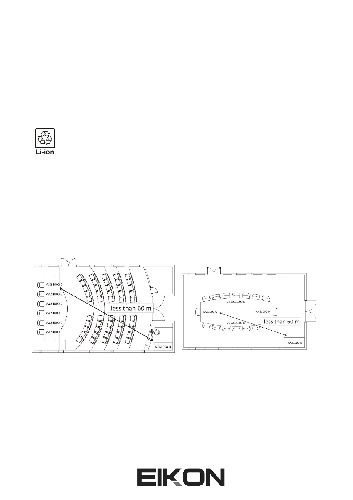
ROOM LAYOUT AND COVERAGE AREA
Choose the receiver location checking the real coverage area of conference room (usually coverage area of
conference room is smaller than the conference room area).
Typically in a closed space the maximum distance of any transmitter unit from the receiver unit must be less
than 60 m (200 ft). We suggest to check carefully the receiver installation to find the best location: wall
reflections, rack mounting and interference from other electronic equipment or metal furniture can influence
the RF signals and, consequently, the features of the WCS1000 system.
Example of conference room: Example of meeting room:
WCS1000RXV2 RECEIVER UNIT INSTALLATION
The WCS1000RXV2 receiver unit must be installed on a table or in 19” rack and the audio output must be
connected to the conference room audio system.
Keep the receiver away from high-power and strong radiation equipment or it may influence the system
receiving performance.
There are 4 antennas to be connected to receiver unit:
1 x ANT DATA: 426 Mhz antenna for control DATA, it must be connected to DATA ANT connector.
3 ANT : 2 x ANT A 660 Mhz 1 x ANT B: 630 Mhz antenna for CHAIRMAN and DELEGATE microphone units, it
must be connected to ANT A and ANT B connectors.

11
IMPORTANT: the different receiver antennas must be connected in correct positions or the system
will work properly.
WCS1000RXV2 RECEIVER UNIT SET-UP
WCS1000RXV2 receiver’s most used parameters can be set in the STANDARD menu, while more in-deep
parameters can be set in the SYSTEM SETTING menu.
To visualize the SYSTEM SETTING menu press and hold the SET button while powering up the receiver. The
display will show:
Release the SET button and the display will show the Room setting:
Pressing the UP and DOWN buttons you can choose the Room control channel within the range of
0-9, A-F. This is the RF channel used by the system to exchange control data between the receiver and the
microphone units. Each channel corresponds to a frequency and a free frequency channel must be selected.
When choosing a control channel try to avoid channels used by other RF apparatus or other
WCS1000 systems in adjacent rooms.
The receiver and all the transmitter units must be set always on the same room CONTROL
channel.
In the majority of the UE countries the range for remote control SRD is 433.050-434.790 MHz,
that corresponds to the Room channels B and C. In any case please consult your national
spectrum authority to set a proper frequency channel.
Pressing again the SET button the display shows the Delegate RF activation setting:
Pressing the UP and DOWN buttons you can enable [1] or disable [0] a delegate unit RF channel. Pressing

12
again the SET button you can also select RF channels D2 or D3. D4 cannot be disabled because at least one
channel must be active.
TIP:this function is useful to reduce the number of delegate RF channels that can be active
simultaneously. For example, in case of two adjacent meeting rooms using two WCS1000 system, if
you reduce the active channels of both systems to two each they can both operate in a more
reliable way.
NOTE: regardless of how many RF channels are active, the maximum number of delegate units that
can be used in a WCS1000 system is always 256, see also the delegates set-up operation further in
this manual.
Pressing again the SET button the display shows the Test setting:
This is a FACTORY mode used for the device test.
Pressing again the POWER button the receiver will be initialized and enter the STANDARD operating mode:
The display will show the last set-up status (the following is an example):
This is the STANDARD menu and the most used parameters can be set here.
Pressing the SET button one time is possible to set the CHAIRMAN PRIORITY MODE: by pressing UP or
DOWN button you can select CFREE or CONLY.
: in this mode, when the chairman presses the PRIORITY button all delegates are shut down and
he has the priority to speak, but any delegate can speak again together with the chairman just by pressing his
TALK button.
: when the chairman presses the PRIORITY button all delegates are shut down and he has the
priority to speak, but in this case the delegates cannot speak until the chairman gives the word to them by
releasing the priority (pressing the TALK button).
Pressing the SET button two times it’s possible to set the maximum NUMBER OF ACTIVE DELEGATES that can
speak simultaneously. By pressing UP or DOWN button the number of delegates can be set from 1 to 4:

13
Pressing the SET button three times is possible to set the DELEGATE PRIORITY MODE. By pressing UP or
DOWN button this mode can be set as LIMIT or as FIFO:
: with the delegate priority set as LIMIT, once the maximum NUMBER OF ACTIVE DELEGATES
has been reached, no other delegates can speak until one or more active delegates shut off their
microphone. For example, with 1MAX LIMIT setting only one delegate can speak at the time and no other
delegate can speak until he/she has finished to talk and has released the TALK button.
: with the delegate priority set as FIFO, once the maximum NUMBER OF ACTIVE DELEGATES has
reached, the next delegate activating the microphone automatically shuts off the microphone of the first
active delegate, so the priority is like a sequence of First In / First Out. For example with 1MAX FIFO setting
only one delegate can speak at the time and any other delegate can shut him/her off and talk just by pressing
the TALK button.
WCS1000RXV2 AUDIO RF CHANNEL SET-UP
When the WCS1000RXV2 is turned ON, the last audio RF channel setting appears on the display, for example:
The first number is the chairman audio RF channel while the following numbers, within the square brackets,
are the delegate audio RF channels. The chairman channel operates in the 610-634 MHz range, the delegate
channels operate in the 640-634 MHz range, with a channel separation of 250KHz.
The chairman and delegate channels operates in different ranges, so there is no interference
between them. However all delegate channels operate in the same range, so the channel
numbers must be different to avoid interferences.
To set the audio RF channel channels you can operate manually or use the auto-scan function.
Manual setting
Press SET key one or several times until the channel number is flashing. Then press UP or DOWN button
to select the channel and then press SET to save it or wait about 3 seconds until the system has saved the
setting automatically (the number will stop flashing).
Auto-scan setting
Press SET key one or several times until the channel number is flashing and then press and hold the SET key
until the display shows the symbol ---. Release the key and the system will scan all audio channel (00-76) and
automatically select the best one.
In order to select the correct frequency for each channel and to avoid interferences, we suggest to use the
following procedure:
1) Set the first delegate channel in the receiver unit. Then switch on the first delegate microphone and
press the TALK button, leaving the unit active.
2) Set the second delegate channel in the receiver unit. Then switch on the second delegate
microphone and press TALK button, leaving the unit active.
3) Repeat the procedure for delegate channel three and four.
14
TIP:if there are other radio-frequency transmitters in the same coverage area where the WCS1000
system is used, we suggest to turn them on when setting the RF channels using auto-scan, so the
system will choose frequencies that are truly free.
IMPORTANT NOTE: the transmitting channels are set on the receiver unit only. The WCS1000RX
manages the RF channels and tell to the chairman and delegate units which RF channel they have
to use. To do that WCS1000RXV2 uses the room control channel and this is why it’s so important
that the room control channel is the same for all units. See above about how to set the room
control channel on WCS1000RXV2, further in the manual you can see how to set it on transmitter
units.
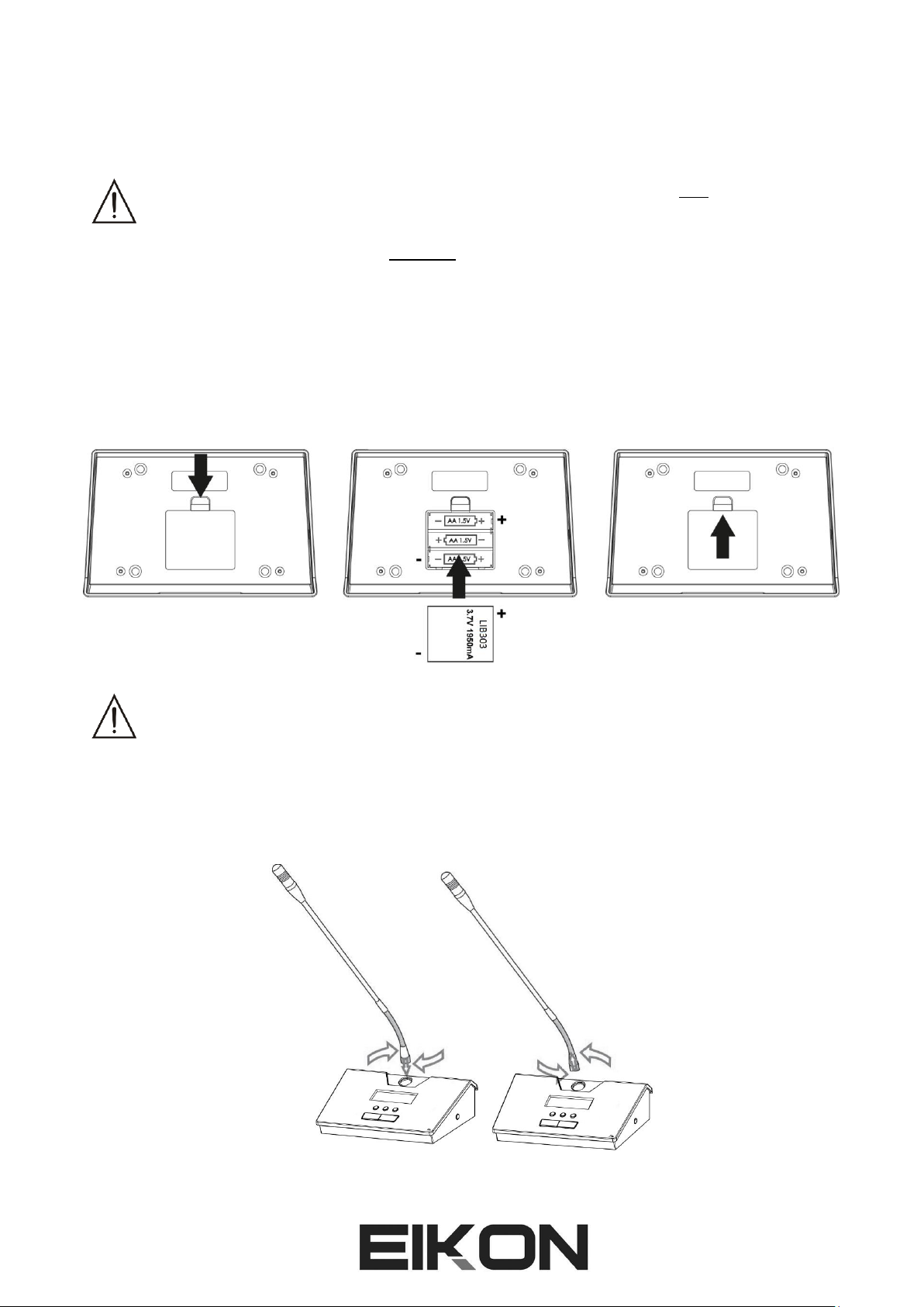
WCS1000CV2 and WCS1000DV2 INSTALL OR REPLACE THE BATTERY PACK
When the display on WCS1000CV2 or WCS1000DV2 units shows a low battery level or when the battery pack
is completely exhausted, replace the battery pack as follows:
IMPORTANT: be careful to respect always the polarity marked inside the battery inlet.
Remove the batteries if you don’t use the microphone for a long period of time: this will avoid the
corrosion of the battery contacts.
WCS1000CV2 and WCS1000DV2 MICROPHONE INSTALLATION
To install the microphone gooseneck into the base, insert it to the base connector, then turn it until it slides
slightly into the connector. When it is inserted completely (be careful to not force it!), screw the security ring
clockwise:
To remove the gooseneck unscrew the security ring before disconnecting.

15
WCS1000CV2 and WCS1000DV2 TRANSMITTER UNIT SET-UP
Press the POWER button to switch the microphone unit while keeping pressed the MUTE button: the
microphone unit enters in SETTING mode with the first parameter flashing. You can select the next
parameter by pressing again the MUTE button and you change a parameter value using the and
buttons. If you press again POWER button or wait 9 secs the microphone unit will exit from setting mode.
The parameter are:
This is the room control channel in the range of 0-9,A-F. Each channel corresponds to a frequency and
you must set the same frequency channel previously set on the WCS1000RX receiver.
The receiver and all the transmitter units of the same conference system must be set always on
the same Control Room Channel.
Chairman microphone unit ID setting: this number can be set from 0-9, A-F for a total 16 ID
chairman units in the system. However, in a typical conference system there is only one chairman.
Delegate microphone unit ID setting: this number can be set from 0-255, for a maximum
256 ID different delegate units in the conference system.
All microphone ID in one system must be different: if different units have the same ID number,
the system will not work properly.
Chime of chairman microphone: when the chairman presses the PRIORITY button, the system playa a
chime sound to advise all delegates that he/she is taking the word. Setting this parameter as no chime
sound is played.

16
CONFERENCE SYSTEM AUDIO CHECK
If you had followed all previous set-up instructions, your conference system should be set to operate
properly. At this point finally you have to check the audio system following these instructions.
Connect the receiver WCS1000RXV2 to the conference room’s audio system.
Set the level controls of your audio system at mid position or “0” level.
Then turn on the WCS1000RXV2 receiver and set all the level knobs to minimum.
Press the talk button on the transmitter unit and speak loudly at the microphone.
Set the VOL level using the buttons on the transmitter unit
Meanwhile check the optimal level on the LED bar: all LED light except the PEAK LED.
Typically the VOL bar on the transmitter display should be placed in the ¼ to ¾ range.
Finally raise up the VOL knob on the WCS1000RXV2 receiver and set the volume to an
audible e comfortable level, avoiding feedback noise. Typically the knob should be stay in
the ½ to ¾ range.
Repeat this procedure for each transmitter and finally check the whole system with the maximum number of
5 microphone active: if there is any audio feedback, reduce the main level of the audio system.
WCS1000RXV2 LOCK & UNLOCK
After the system is set-up properly, it could be useful to lock all the buttons on the receiver in order to avoid
inappropriate operation from unauthorized person.
LOCKING: Press and hold the SET button first, then press UP button, the display will show:
UNLOCKING: Press and hold the SET button first, then press DOWN button, the display will show:

17
TECHNICAL SPECIFICATION
WCS1000RXV2 –Conference System UHF Receiver
RF Channels
76 frequency preset for delegate audio UHF band
16 frequency preset for chairman audio UHF band
16 frequency preset for control room data UHF band
RF Frequency Band
Delegate audio UHF: 640.000 - 664.750 MHz
Chairman audio UHF: 610.000 - 634.750 MHz
Control room data UHF: 422.400-439.400 MHz (see
national limitation)
RF Receiver Type
PLL UHF Synthesized
RF Power
Data: max 10 mW
RF Modulation type
Data: FSK (duty cycle less 10%)
RF Sensibility
-105 dBm / 12 dB SINAD
RF Image/Spurious Rejection
> 70 dB
RF Interference Rejection
> 70 dB
RF Frequency Stability
± 0.005% (-10 ÷ +40 °c)
THD Distortion
< 0.8%
S/N Ratio
> 90 dB
Dynamic Ratio
> 105 dB
Frequency Response
50 Hz –15 KHz (±3 dB)
nominal audio output
0 dBu
Power Supply
12-15 VDC 2 A
Dimensions (WxDxH)
485 ×355 × 85 mm
Weight
7.0 Kg
WCS1000CV2 & WCS1000DV2 –Microphone unit UHF Transmitter
RF Channels
76 frequency preset for delegate audio UHF band
16 frequency preset for chairman audio UHF band
16 frequency preset for control room data UHF band
RF Frequency Band
Delegate audio UHF: 640.000 - 664.750 MHz
Chairman audio UHF: 610.000 - 634.750 MHz
Control room data UHF: 422.400-439.400 MHz (see national
limitation)
RF Power
Audio: max 10 mW
Data: max 10 mW
Modulation method
Audio: FM (F3E)
Data: FSK (duty cycle less 10%)
RF Max deviation
60 KHz
RF Frequency Stability
± 0.005% (-10 ÷ +40 °c)
Spurious Emission
under limits EN 300422
Frequency Response
50 Hz –15 KHz (±3 dB)
Microphone type
Electrect hyper-cardioid
Power Supply
Lithium rechargeable battery pack
Dimensions (WxDxH)
170 × 58 × 120 mm
Weight
0.7 Kg
WCS1000CH Battery Charger
Power supply
110 –240 V~ 50Hz / 60Hz
Consumption
200 W

18
Battery pack type
3.7 VDC Li-Ion rechargeable
Number of Battery pack
16
Max charging current
700 mA
Charging time
2 hours
Dimensions (WxDxH)
620 × 370 × 175 mm
Weight
9 Kg
IRC14430X3 Li-Ion Battery Pack
Rated voltage
3.7 VDC
Discharge current
<500 mA
Charging current
<700 mA
Time of speaking
>8 hours
Time of standby
>24 hours
Dimensions (WxDxH)
47 × 40 × 12 mm
Weight
54 g

19
TRATTAMENTO DEL DISPOSITIVO ELETTRICO OD ELETTRONICO A FINE VITA.....................................20
AVVERTENZE PER LA SICUREZZA..........................................................................................................20
IN CASO DI GUASTO .............................................................................................................................20
IMBALLAGGIO, TRASPORTO E RECLAMI...............................................................................................20
GARANZIE E RESI..................................................................................................................................20
MANUTENZIONE E LIMITAZIONI D’USO...............................................................................................21
ALIMENTAZIONE...................................................................................................................................21
AVVERTENZE PER L’UTILIZZO E CONFORMITÀ CE ................................................................................22
INTRODUZIONE ....................................................................................................................................23
DESCRIZIONE........................................................................................................................................23
FEATURES .............................................................................................................................................23
WCS1000RX UNITÀ RICEVITORE...........................................................................................................23
WCS1000CV2 e WCS1000DV2 UNITÀ TRASMETTITORE ......................................................................25
WCS1000CH CARICA BATTERIE ............................................................................................................26
LIB303 pacco batteria Li-Ion.................................................................................................................27
ISTRUZIONI DI IMPOSTAZIONE.............................................................................................................28
DISPOSIZIONE IN AMBIENTE E AREA DI COPERTURA ..........................................................................28
INSTALLAZIONE DEL RICEVITORE WCS1000RXV2 ................................................................................28
CONFIGURAZIONE DEL RICEVITORE WCS1000RXV2............................................................................29
IMPOSTAZIONE DEI CANALI AUDIO RF SU WCS1000RXV2 ..................................................................31
INSTALLARE O SOSTITUIRE LE BATTERIE SU WCS1000CV2/DV2..........................................................32
INSTALLAZIONE DEL MICROFONO SU WCS1000CV2/DV2...................................................................32
IMPOSTAZIONE DELLE UNITÀ TRASMETTITORE WCS1000CV2/DV2....................................................32
CONTROLLO AUDIO DEL SISTEMA PER CONFERENZA..........................................................................33
BLOCCO E SBLOCCO DEL WCS1000RXV2 .............................................................................................34
SPECIFICHE TECNICHE ..........................................................................................................................35
FIG.1 .....................................................................................................................................................37
FIG.2 .....................................................................................................................................................37
FIG.3 .....................................................................................................................................................38
FIG.4 .....................................................................................................................................................38

20
TRATTAMENTO DEL DISPOSITIVO ELETTRICO OD ELETTRONICO A FINE VITA
Il marchio riportato sul prodotto o sulla documentazione indica che il prodotto non deve essere
smaltito con altri rifiuti domestici al termine del ciclo di vita. Per evitare eventuali danni
all’ambiente si invita l’utente a separare questo prodotto da altri tipi di rifiuti e di riciclarlo in
maniera responsabile per favorire il riutilizzo sostenibile delle risorse materiali. Gli utenti
domestici sono invitati a contattare il rivenditore presso il quale è stato acquistato il prodotto o l’ufficio locale
preposto per tutte le informazioni relative alla raccolta differenziata e al riciclaggio per questo tipo di
prodotto. Gli utenti aziendali sono invitati a contattare il proprio fornitore e verificare i termini e le condizioni
del contratto di acquisto. Questo prodotto non deve essere smaltito unitamente ad altri rifiuti commerciali.
AVVERTENZE PER LA SICUREZZA
•ATTENZIONE - Prima di utilizzare il prodotto, si prega di leggere attentamente le seguenti istruzioni
per la sicurezza. Prendere visione del manuale d’uso e conservarlo per successive consultazioni.
Durante l’uso di un prodotto elettrico devono essere sempre prese precauzioni di base onde evitare
danni a cose o persone, incluse le seguenti:
•In presenza di bambini, controllare che il prodotto non rappresenti un pericolo.
•Posizionare l’apparecchio al riparo dagli agenti atmosferici e a distanza di sicurezza dall’acqua, dalla
pioggia e dai luoghi ad alto grado di umidità.
•Collocare o posizionare il prodotto lontano da fonti di calore quali radiatori, griglie di riscaldamento e
ogni altro dispositivo che produca calore.
•Evitare che qualsiasi oggetto o sostanza liquida entri all’interno del prodotto.
•Il prodotto deve essere connesso esclusivamente alla alimentazione elettrica delle caratteristiche
descritte nel manuale d’uso o scritte sul prodotto.
IN CASO DI GUASTO
•In caso di guasto o manutenzione questo prodotto deve essere ispezionato da personale qualificato
quando:
▪Sostanze liquide sono penetrate all’interno del prodotto.
▪Il prodotto è caduto e si è danneggiato.
▪Il prodotto non funziona normalmente esibendo una marcato cambio di prestazioni.
•Non intervenire sul prodotto.
•Rivolgersi a un centro di assistenza autorizzato Proel.
IMBALLAGGIO, TRASPORTO E RECLAMI
•L’imballo è stato sottoposto a test di integrità secondo la procedura ISTA 1°. Si raccomanda di
controllare il prodotto subito dopo l’apertura dell’imballo.
•Se vengono riscontrati danni informare immediatamente il rivenditore. Conservare quindi l’imballo
completo per permetterne l’ispezione.
•Proel declina ogni responsabilità per danni causati dal trasporto.
•Le merci sono vendute “franco nostra sede” e viaggiano sempre a rischio e pericolo del distributore.
•Eventuali avarie e danni dovranno essere contestati al vettore. Ogni reclamo per imballi manomessi
dovrà essere inoltrato entro 8 giorni dal ricevimento della merce.
GARANZIE E RESI
•I Prodotti Proel sono provvisti della garanzia di funzionamento e di conformità alle proprie specifiche,
come dichiarate dal costruttore.
•La garanzia di funzionamento è di 24 mesi dopo la data di acquisto. I difetti rilevati entro il periodo di
garanzia sui prodotti venduti, attribuibili a materiali difettosi o difetti di costruzione, devono essere
tempestivamente segnalati al proprio rivenditore o distributore, allegando evidenza scritta della data
di acquisto e descrizione del tipo di difetto riscontrato. Sono esclusi dalla garanzia difetti causati da
Table of contents
Languages:
Popular Conference System manuals by other brands


Lars Thrane
Lars Thrane LT-3100 User & installation manual

Aastra
Aastra OpenCom 100 Mounting and Commissioning User Guide

Toa
Toa TS-780 operating instructions

Lucent Technologies
Lucent Technologies MERLIN LEGEND Release 7.0 System planning

Paso
Paso PM2045-V Instructions for use

Crestron
Crestron UC-CX100-T quick start