vissonic VIS-DMD-T User manual

www.vissonic.com
1VISSONIC ELECTRONICS LIMITED
VISSONIC ELECTRONICS LIMITED

www.vissonic.com
2VISSONIC ELECTRONICS LIMITED
Meaning of Symbols
■Safety instructions
Symbols are used in the operation manual and the equipment to indicate the possible injury to users or others and the potential
risk of property losses, so that you can use the equipment safely and correctly. The instructions and their meanings are as below.
Please make sure you understand these instructions correctly before reading the manual.
Users are reminded to operate and maintain the equipment
according to the operation and maintenance instructions
along with it. Ignoring this information may lead to death or
personal injury due to faulty operation.
Users are also reminded that uninsulated dangerous voltage
in the equipment may cause electric shock.
CE certification indicates that the product has met the safety
requirements specified by the European Union, and users can
use it safely.
ISO9001-2000
This product has been certified by ISO 9001 international
quality system.
Warning: To avoid electric shock, please do not open the
cover, and do not put useless parts in the cabinet. Contact
qualified customer’s service personnel.
■General Information instructions
It lists the contents that may cause unsuccessful operation or
setting and some relevant information that requires attention.

www.vissonic.com
3VISSONIC ELECTRONICS LIMITED
Important notes
Warning
To ensure the reliable use of the equipment and the
safety of personnel, please observe the following
considerations during the installation, use and
maintenance:
Installation considerations
◆Both the power plug and the front panel
disconnecting coupler shall be easy to disconnect.
◆The equipment shall not be exposed to water drops
or splashes, and articles filled with water such as
vases shall not be placed on the equipment.
◆Please do not use the product in the following
places, including those with dust, oil fume,
conductive dust, corrosive gas and combustible gas,
those exposed to high temperature, condensation,
wind and rain, or those with vibration and impact.
Electric shock, fire and misoperation can also lead to
product damage and deterioration;
◆During the screw hole drilling and wiring, do not
make the metal chips and wire ends fall into the vent
hole of the controller, which may cause fire, fault or
misoperation;
◆At the end of the installation work, it is necessary
to ensure that there are no foreign matters on the
ventilation surface, including dust-proof paper and
other packaging items, otherwise it may lead to poor
heat dissipation during operation, and cause fire, fault
or misoperation;
◆Avoid wire connection in live state, plugging and
unplugging cables, otherwise it is easy to cause
electric shock or circuit damage;
◆Installation and wiring must be firm and reliable.
Poor contact may lead to misoperation;
◆For the application with serious interference, the
input or output cable of high frequency signal shall be
shielded cable to improve the anti-interference
performance of the system.
Considerations in wiring
◆The equipment shall be connected to a grid power
outlet with a protective earth connection.
◆Installation and wiring can be carried out only after
all external power supply is cut off, otherwise electric
shock or equipment damage may be caused;
◆The product is earthed through the earthing
conductor of the power wire. To avoid electric shock,
the earthing wire must be connected with the earth.
Before connecting the input or output end of the
product, please make sure that the product is correctly
earthed;
◆After the installation and wiring, remove the
foreign matters immediately. To avoid electric shock,
please place the terminal cover of the product
properly before powering on;
Considerations in operation and maintenance
◆Do not touch the terminal when it is powered on,
otherwise it may cause electric shock and
misoperation;
◆Please clean and tighten the terminals after the
power is off.
When the power is on, these operations may cause
electric shock;
◆Please connect or remove the communication
signal cable, and connect or remove the cable of
expansion module or control unit after the power is
off, otherwise the equipment may be damaged and
misoperated;
◆Do not disassemble the equipment to avoid
damaging the internal electrical components;
◆Be sure to read through this manual, and change,

www.vissonic.com
4VISSONIC ELECTRONICS LIMITED
test run, start and stop the procedure after fully
confirming the safety;
◆The button cell must be replaced in case of power
failure. If replacement in live state is needed when
considering the equipment operation, it must be
carried out by a professional electrical technician
wearing insulated gloves.
Considerations in product scrapping
◆Explosion of electrolytic capacitor: the electrolytic
capacitor on the circuit board may explode when it is
burned;
◆Please collect and dispose of them by category ,
and do not put them into a household waste bin.
◆Please treat it as industrial waste or according to
local environmental protection regulations.

www.vissonic.com
5VISSONIC ELECTRONICS LIMITED
NOTE
This manual mainly describes the use, performance parameters and troubleshooting of VISSONIC VIS-DMD-T
all-in-one touch screen conference unit.
If the technical parameters and system use in this manual are changed, the manufacturer will update the version
number of the manual. Please make sure to use the latest product manual. The copyright of the manual belongs
to VISSONIC Electronics Ltd. This manual is protected by the Copyright Law of the People’s Republic of China
and other intellectual property laws and regulations. It is not allowed to copy part or all of the manual or modify
this manual without permission.
Version
Updated content
Date
1.0
Issue
11.12.2020

www.vissonic.com
6VISSONIC ELECTRONICS LIMITED
Table of Contents
1. Product Overview....................................................................................................................................................... 7
1.1 Product description and layout......................................................................................................................... 7
1.2 Product connection diagram............................................................................................................................. 9
2. Basic function of the product....................................................................................................................................10
2.1 Display of main interface information........................................................................................................... 10
2.2 Speech timing and speech request..................................................................................................................11
2.3 Unit language and brightness setting..........................................................................................................11
2.4 Unit sound effect setting and unit information display............................................................................ 12
2.5 Call service.....................................................................................................................................................12
2.7 Conference mode.......................................................................................................................................... 13
3. Unit ID setting, unit type setting and authority setting............................................................................................ 14
3.1 Edit unit ID....................................................................................................................................................14
3.2 Unit type setting............................................................................................................................................ 15
3.3 Unit authority setting................................................................................................................................... 15
3.4 Microphone status indication...................................................................................................................... 16
4. Optional functions.....................................................................................................................................................16
4.1 IC card sign-in and information display function.......................................................................................... 16
4.2 Voting function.............................................................................................................................................. 16
4.3 Interpretation unit setting and channel number selection....................................................................... 18
4.4 Bluetooth module..........................................................................................................................................20
4.5 Dual-user module..........................................................................................................................................20
5. Upper computer software setting..............................................................................................................................21
5.1 Software connection......................................................................................................................................21
5.2 Basic configuration....................................................................................................................................... 22
5.3 Information uploading................................................................................................................................. 23
5.4 Display of request to speak.......................................................................................................................... 24
5.5 Dynamic text..................................................................................................................................................24
6. Debugging................................................................................................................................................................ 25

www.vissonic.com
7VISSONIC ELECTRONICS LIMITED
1. Product Overview
1.1 Product description and layout
The VIS-DMD-T is a multimedia conference unit based on the VISSONIC AUDIOLINK multimedia IP
network technology. It is equipped with a 4.3-inch touch screen, which improves the flexibility of the
conference and the interactivity of the conference content. The same conference discussion unit can set as
chairman, delegate, VIP or dual-user unit according to the requirements of the conference. As the various
requirements of conference and with the same hardware, it can upgrade the software to achieve more
functions without changing unit or hardware.
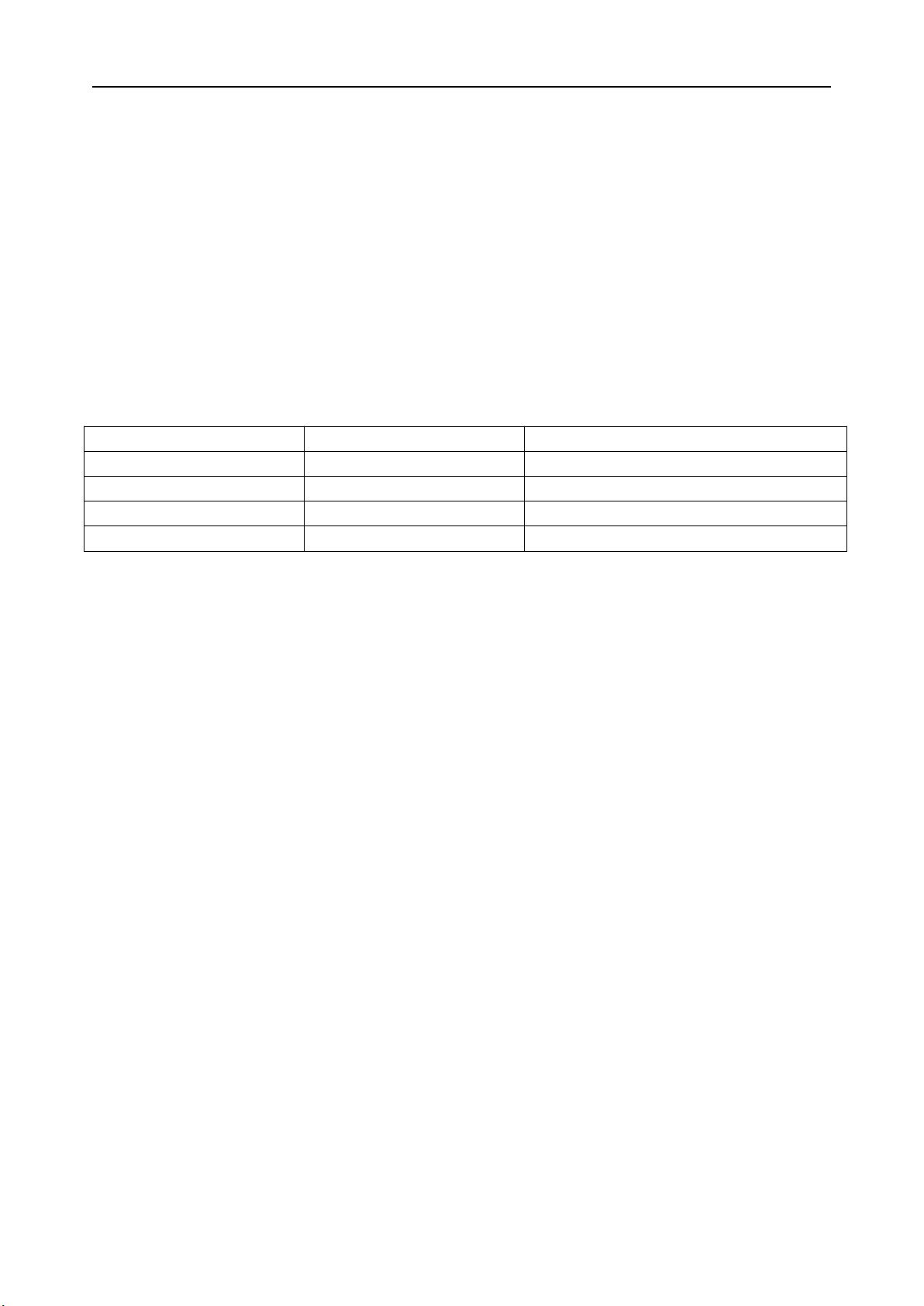
The current software module contains five functions: vote, NFC card identification, simultaneous
interpretation channel, dual user and Bluetooth. By chairman unit, you can use the touch screen on the
VIS-DMD-T unit to manage different aspects of the conference. It allows you to start, pause meetings, view
request-to-speak lists, approve request, view addresser profiles and speaking times, and even record meetings,
easily start and stop voting etc.
By delegate unit, you can view the agenda under discussion and the remaining time to speak. You can even
see who is speaking and the position you are on the speaking list.
Functions:
● The design is compact, ergonomic and modern
● The connection cable may select the outlet hidden at the bottom, convenient for maintaining clean desktop,
or the outlet in the back, adaptable to various engineering demands.
● Adopt standard CAT5e with RJ45 connector as the connection cable, which is convenient for standardized
engineering wiring installation and maintenance. The installation wire clamps attached make the system more
robust and stable.
● All-in-one touch screen conference unit can be set as the chairman, delegate, VIP or dual delegate unit or
any conference device via conference system software or the menu of conference controller front panel.
● Chairman unit can pause the delegate's speech, close the delegate's speech, view the speaking request list,
agree or reject the delegate's speech request, and functions of starting conference recording, stopping
recording, selecting conference topics, initiating sign-in, and voting.
● Delegate unit can request to speak and view your position in the request list, information of the addresser,

www.vissonic.com
8VISSONIC ELECTRONICS LIMITED
and view the meeting topic.
● The system can set up to 32 VIP delegate units. As long as the total number of microphones already turned
on in the system does not exceed 8, the VIP delegate unit can be turned on freely.
● The touch screen software of the conference unit contains five optional function modules:
- Voting: three-button / two-button voting
- NFC identification: Sign in with NFC card to accurately identify user information.
- Simultaneous interpretation channel: support 2 language channel selectors, each selector supports 64
languages independent selection.
- Dual users: Support two participants sharing one unit to achieve camera tracking at two locations; enabling
two delegates to vote on one unit.
- Bluetooth: can be connected to hearing aids etc.
● 4.3-inch capacitive touch screen displays conference information, such as agenda, addresser information,
addresser list and request-to-speak list, speech timing, timing speaking, current time and date, Chinese and
English switching, and checking unit version information.
● The conference unit has sign-in function and service request function through the touch screen.
● The touch screen background software supports to set the current microphone sensitivity and 8-band
equalizer EQ adjustment.
● Can be configured with gooseneck microphone or rectangular dual backup microphone.
● Dual headphone port design, volume can be adjusted through touch screen.
● Hand-in-hand-loop-network connection and star connection, the system is more reliable. Replacement and
one unit or failure of cable will not affect the normal operation of other units in the system.
● Hot plug-and-play for conference unit, automatic recovery.
● The number of speakers limit function: you can set the speaker units that are turned on at the same time (the
number is 1/2/4/6, and a maximum of 32 units are allowed to speak in the full-open mode).
● Has the following speaking modes:
"OPEN" open mode, "VOICE" voice control mode, "OVERRIDE” first-in first-out
● mode, "APPLY" application mode, "PTT" press and hold to speak (optional), "ALL" full open mode
(optional), combined with camera and a camera tracking controller, it has an automatic camera tracking
function.

www.vissonic.com
9VISSONIC ELECTRONICS LIMITED
1.2 Product connection diagram

www.vissonic.com
10 VISSONIC ELECTRONICS LIMITED
2. Basic function of the product
Setting of the interface:
Click the setting button to enter the setting menu, which can set the unit language, brightness, sound effect, unit
information, voting and tea service.
2.1 Display of main interface information
Two simultaneous interpretation channels displayed by the main interface can be used by two users. The dual
display
of digital time and dial time as well as date
display make the appearance of the
unit more concise and attractive. Click the setting button on the left to enter the unit function setting interface,
and click the simultaneous interpretation button on the right to enter the simultaneous interpretation channel

www.vissonic.com
11 VISSONIC ELECTRONICS LIMITED
setting of the interface.
2.2 Speech timing and speech request
When you click the microphone button, the microphone start interface will display the speech time of the
participants in real time. The information of the addresser and addresser in the request list can be displayed
after closing the microphone. The chairman unit has the function of closing the microphone of the addresser's
representative unit, and has the authority to approve or reject the representative unit’s request for speaking
(except for other hosts). The user information corresponding to the unit shall be set in the upper computer
software of VIS-DCP2000 series conference host (refer to the operation instructions of VIS-DCP2000 series
upper computer software).
2.3 Unit language and brightness setting
In the unit setting, the system provides Chinese and English display switching setting (if you need other

www.vissonic.com
12 VISSONIC ELECTRONICS LIMITED
languages, we can provide customized service) and screen brightness custom adjustment.
2.4 Unit sound effect setting and unit information display
The "sound effect" setting provides 8-band equalizer adjustment and + - 12dB sensitivity adjustment. It can be
set to Open and Close, and it can also be reset with one key if the setting is disturbed.
You can view the unit authority and status information in “About’ setting. It includes unit type, current ID
number, voting authority, speaking authority and software version.
2.5 Call service
The system provides call service function, and customized one-key call services such as pen, paper and tea.
The computer software can receive call information, and provide comfortable and fast service for the
conference.

www.vissonic.com
13 VISSONIC ELECTRONICS LIMITED
2.7 Conference mode
When we turn on the conference processor, the initialization information of "initializing..." will be displayed on the
screen. After 3 seconds, the main screen menu will be displayed.
Main screen
U n i t : 0 0 0 1
M I C : O v e r r i d e / 1
The information displayed on the main screen is as shown in the figure above, including Unit (indicating the
number of conference microphone units connected to the system from "0001" to "4000"), conference mode
("Override, Voice, Open, Apply"), and maximum number of speeches (1, 2, 4, 6 optional).
Microphone mode
On the main screen, we can quickly enter the microphone mode setting interface by pressing '▽’ . If the conference
host is connected to PC, you can also set the conference mode through the conference software
Menu
Parameters
Description
MIC mode
Override
Open
Voice
Apply
Override
Open
Voice
Apply
Mode
Description
Override
In the Override mode, the representative unit directly turns on and off the
microphone through the microphone switch button. When the number of
representative units reaches the maximum value set, the next representative unit
turning on the microphone will automatically turn off the unit first turning on the
microphone.
Open
In the Open mode, the representative unit directly turns on and off the microphone
through the microphone switch button. When the number of representative units
reaches the maximum value set, the representative unit to be turned on next will be
added to the waiting list and enter the waiting state until any unit in the on state
turns off the microphone.
Voice
In the Voice mode, the representative unit controls turning on and off the
microphone through intelligent recognition of the nearest human voice. When the
microphone detects the nearest voice source, it will turn on automatically and
immediately. When the number of representative units to be turned on reaches the
maximum value set, the next representative unit turning on the microphone will
automatically turn off the unit first turning on the microphone... (For special
requirements, we can change to turn on 20 microphones freely)
Apply
In the Request mode, the representative unit requests to turn on the microphone
through the microphone button. In the Request status, the LED light of the
conference unit is in green. The chairman presses the agree speech button or

www.vissonic.com
14 VISSONIC ELECTRONICS LIMITED
reject button to decide whether the representative can turn on the microphone.
When the speaking representatives reach the maximum number of addressers, the
system allows the same number of representative units to enter the waiting list.
Maximum speech number of Active MIC
In the main screen state, press the ' △’ button to quickly enter the setting interface of the maximum number of
microphones allowed.
Menu
Parameters
Description
Active MIC
1,2,4,6
Limit the number of
representatives’ microphones
allowed to be turned on
Monitoring information, display unit connection information
Menu
Parameters
Description
UNIT
0000~4000
Display the number of
conference microphones
connected to the system,
monitor the connection status
of the system in real time,
and help to find the unit
failure and connection failure
in time.
3. Unit ID setting, unit type setting and authority setting
3.1 Edit unit ID

www.vissonic.com
15 VISSONIC ELECTRONICS LIMITED
Press and hold the 'ESC' button on the host panel for 2 seconds, then the system will enter the editing ID status.
Click the microphone on button of the unit in turn (the button turns red, ID starts from No. 1 by default, and
the ID is increased by one by pressing the unit once) until the last unit. During editing, the unit displays the
local ID (ID before editing) and the current ID (ID after editing).
Note: the unit ID can not be the same, otherwise the unit may be on and off at the same time due to ID conflict,
and there may be noise or there is no audio output when the microphone is turned on, so it is necessary to edit
the unit ID again.
3.2 Unit type setting
Press ENTER to enter the main menu, press▼ to find the 'Delegate Setup' setting, and enter the submenu setting
'Unit Type Set'.
U n i t T y p e S e t
D e l e g a t e S e t u p :
If the unit is the representative unit by default at this time, and most of the units are the representative units in
a conference, first we need to set the status ' Type: ON.'
Press the unit microphone button, then the screen will display "representative->chairman->interpreter->VIP"
circularly. Unit type can be set according to conference needs.
After setting all types, turn off the type setting status, and then restart the host to complete the setting.
O f f
T y p e : O f f
- >
3.3 Unit authority setting
Log into the administration software of the upper computer of the conference system. In the
administration mode, right-click the unit icon and click personnel authority to set unit authority, such
as ID, speaking, voting, sign-in authority, etc.

www.vissonic.com
16 VISSONIC ELECTRONICS LIMITED
3.4 Microphone status indication
Microphone switch button , LED ring on gooseneck microphone and display screen will display different
working states of conference unit.
Microphone button
color
LED ring color
Display screen
Status
Red (ON)
Red (ON)
Microphone ON
Microphone ON
White (OFF)
Green (WAIT)
Requesting to speak
Please wait....
Request to speak
4. Optional functions
4.1 IC card sign-in and information display function
Sign in through NFC card, and accurately identify user image information, name, position, etc. (Add user details in
the system management software. Refer to 5.2 ~ 5.3.)
4.2 Voting function

www.vissonic.com
17 VISSONIC ELECTRONICS LIMITED
Voting at election
Voting by rating
Voting by ballot

www.vissonic.com
18 VISSONIC ELECTRONICS LIMITED
Sign-in
The results of election, rating, ballot and sign-in can be displayed in real time, and the data can be displayed in
histogram, which is more intuitive and reliable. The chairman unit can start and end voting, and the voting
authority of the unit can be customized. In the conference system administration software, you can start voting
and sign in (you can set IC card to sign in).
4.3 Interpretation unit setting and channel number selection
Enter the host menu 'Interpretation' to set the relevant parameters of the translation unit. Select the number of
channels to be opened, the corresponding language of the channel, and the serial number of the interpretation
booth.
Menu item
Parameters
Parameter value
Description
Max. channel
-
00 to 64
Set the number of simultaneous interpretation
channels according to the actual conference
demands to simplify the channel selection on the
unit.
Channel
00
01
...
64
Chinese, English, ...
(104 languages)
Chinese, English, ...
(104 languages)
Chinese, English, ...
(104 languages)
. Bind the language corresponding to each channel.
The number of channels of the microphone can be
selected according to the number of languages to be
interpreted. The corresponding number of channels
can be set on the host to bind the corresponding
language.
Auto floor
-
On/Off
Turn on the 'On' Auto floor - the interpreter unit turns off
the microphone to stop interpretation, and the channel that
the interpreter unit is responsible for automatically
switches to the original sound of the channel.
Turn off 'Off' Auto floor - the interpreter unit turns off the
microphone to stop interpretation, and the channel that the

www.vissonic.com
19 VISSONIC ELECTRONICS LIMITED
interpreter unit is responsible for has no audio output.
Channel lock
On/Off
On - The output channel of the interpretation unit is
locked and the interpreter can't make the change at will.
Off - The output channel of the interpretation unit can be
set by the interpreter.
Booth setup
Max. booth
Start set
02 to 64
On/Off
Max. booth -- set the number of interpretation booths
On -- start setting, all interpretation units display the
booth no., press the speech button to modify the number,
and the number of the same interpretation booth must be
the same.
Off -- complete setting.
Function - turn on the microphone of any interpretation
unit, and the loudspeaker of the interpretation unit in the
same interpretation booth will turn off automatically.
The microphone unit can select two interpretation channels for dual users at the same time, and each side of
the unit has a 3.5mm headphone jack to receive the interpretation of two channels in the interface.
As shown in the figure, there are two channels CHO01 and CH63 on the left and right sides of the interface.
Click any channel to enter the channel selection interface. Slide up and down to select the language channel
corresponding to the interpretation you want to listen to, and slide the language channel you want to listen to
to the middle of the double horizontal line.

www.vissonic.com
20 VISSONIC ELECTRONICS LIMITED
4.4 Bluetooth module
It is used to connect Bluetooth device, such as a Bluetooth headset, for listening to simultaneous interpretation,
allowing you to enjoy more convenient simultaneous interpretation.
Turn on the Bluetooth setting in the settings, select your Bluetooth device, and make matching connection.
The conference unit will record your Bluetooth device, so that you can enter the Bluetooth range next time
and connect it automatically.
4.5 Dual-user module
Dual-user module is an optional module equipped with two speaking buttons. The two buttons are allocated
different independent ID, two users can use voting, IC card sign-in, simultaneous interpretation, video
tracking and other functions independently without interfering with each other.
Other manuals for VIS-DMD-T
1
Table of contents
Other vissonic Conference System manuals

vissonic
vissonic VIS-MAW-T User manual

vissonic
vissonic VIS-DMD-T User manual

vissonic
vissonic CLEACON User manual

vissonic
vissonic VIS-NP Series User manual

vissonic
vissonic VLI Series User manual

vissonic
vissonic CLEACON User manual

vissonic
vissonic VIS-GSK-F User manual

vissonic
vissonic CLASSIC-D User manual

vissonic
vissonic VLI Series User manual

vissonic
vissonic CLEACON User manual