Eilersen 5024G User manual
Software: StdLim.140630.5v7
Doc. no.: StdLim-140630-5v7-UG-eng
Date: 2020-09-08
Rev.: 5v7
Contact:
Eilersen Electric A/S
Kokkedal Industripark 4
DK-2980 Kokkedal
Denmark
www.eilersen.com
info@eilersen.com
Tel: +45 49 180 100
Fax: +45 49 180 200
5024G User’s guide StdLim
5024G LCD weighing terminal
Basic scale with automatic dosing

2
WWW.EILERSEN.COM
Contents
Contents...................................................................................................................................... 2
Introduction................................................................................................................................ 5
Installation.................................................................................................................................. 5
How to ........................................................................................................................................ 5
–Perform basic operations.................................................................................... 5
–Perform automatic dosing................................................................................... 7
–Change setpoints for automatic dosing .............................................................. 8
Setting Coarse and Fine limits........................................................................... 8
Start/Stop of dosing.......................................................................................... 8
–Change dosing parameters ................................................................................. 9
Change registration period ............................................................................... 9
Change afterflow status.................................................................................... 9
Change afterflow correction............................................................................. 9
–Reading totals.................................................................................................... 10
Reset of totals ................................................................................................. 10
–Operate the menu system................................................................................. 10
–Set date and time.............................................................................................. 10
- Unlock the keyboard.......................................................................................... 11
- Unlock for parameter update ............................................................................ 11
–Enter values....................................................................................................... 12
Entry using selection list ................................................................................. 12
Entry of numbers ............................................................................................ 12
–Check the software version............................................................................... 14
–Activate Intelligent Setup.................................................................................. 15
–Set up the load cell configuration ..................................................................... 15
Load cell communication protocol type ......................................................... 16
Number of load cells....................................................................................... 16
Number of supports........................................................................................ 16
–Detect the load cell configuration..................................................................... 16
–Configure the weighing ranges ......................................................................... 17
–Perform coarse taring ....................................................................................... 17

3
WWW.EILERSEN.COM
–Configure display, filtering and stability requirement ...................................... 18
Interval............................................................................................................ 18
Filters............................................................................................................... 18
Steady/stability detection............................................................................... 18
–Configure zero tracking..................................................................................... 18
–Change reading to high resolution mode.......................................................... 19
–Perform load check ........................................................................................... 19
–Perform corner calibration................................................................................ 19
Corner calibration factor................................................................................. 20
Reset corner calibration factors...................................................................... 20
Corner calibration procedure ......................................................................... 20
–Perform system calibration............................................................................... 22
Calibration factor ............................................................................................ 22
Calibration load............................................................................................... 22
Perform calibration......................................................................................... 23
–Perform linearization ........................................................................................ 23
–Zero with extended range (power-up zeroing)................................................. 24
–Configure Ethernet settings .............................................................................. 25
Address settings.............................................................................................. 25
–Configure Ethernet TCP communication........................................................... 25
Enable TCP protocol........................................................................................ 25
Select TCP port................................................................................................ 25
Select data output........................................................................................... 26
–Check Ethernet communication status............................................................. 26
–Check load cell serial no., exponent and capacity............................................. 27
–Check individual load cell signals ...................................................................... 27
–Check load cell diagnostics................................................................................ 28
Trouble shooting....................................................................................................................... 29
–Error situations.................................................................................................. 29
–Error code display (in NORMAL screen)............................................................ 30
–Error solving (in STATUS screen)....................................................................... 30
Appendices ............................................................................................................................... 31
Appendix A –Installation checklist ...................................................................... 31

4
WWW.EILERSEN.COM
Appendix B –Electrical connections .................................................................... 32
Rear view......................................................................................................... 32
Power Connection........................................................................................... 32
Load cell connection ....................................................................................... 33
Digital I/O connector....................................................................................... 33
RS485 communication .................................................................................... 33
Analog output connector................................................................................ 34
Ethernet connector......................................................................................... 34
Jumper settings............................................................................................... 34
Light Emitting Diodes (LED’s) .......................................................................... 34
Appendix C –Screen overview............................................................................. 35
Appendix D –Filters ............................................................................................. 35
Sampling filter................................................................................................. 35
Display and steady filters................................................................................ 37
Appendix E –Setting of MAC Address.................................................................. 37
Appendix F –Software download ........................................................................ 38
Appendix G –Advanced features......................................................................... 38
Revision History ........................................................................................................................ 39
Contact...................................................................................................................................... 39

5
WWW.EILERSEN.COM
Introduction
This document describes the use of a 5024G LCD display terminal from Eilersen Electric,
when the software version listed on the front page is installed.
With this software, the terminal can perform automatic dosing (coarse/fine) using its digital
outputs and inputs. One digital output is used for coarse dosing and one digital output is
used for fine dosing, while a digital input is used for start of dosing and a digital input is used
for registration of dosed amount.
Installation
The following steps must be performed before the system is used:
•Install the load cells and check mechanical installation
•Optional: Connect digital outputs and digital inputs
•Connect and apply power
•Check software version
•Optional: Activation of Intelligent Setup feature
•Set up load cell configuration
•Power cycle the unit
•Configure weighing ranges
•Perform coarse taring
•Optional: Configure display, filtering, zero tracking range, stability requirement
•Optional: Corner calibration, system calibration, linearization
•Perform load check
Please notice: Perform a load check before the system is used to be sure that all require-
ments regarding accuracy, stability etc. are met before the system is used.
Please notice: If the Intelligent Setup feature is used, this will perform some of the subse-
quent points in the above list.
Details on the steps needed to install the system are explained below.
How to
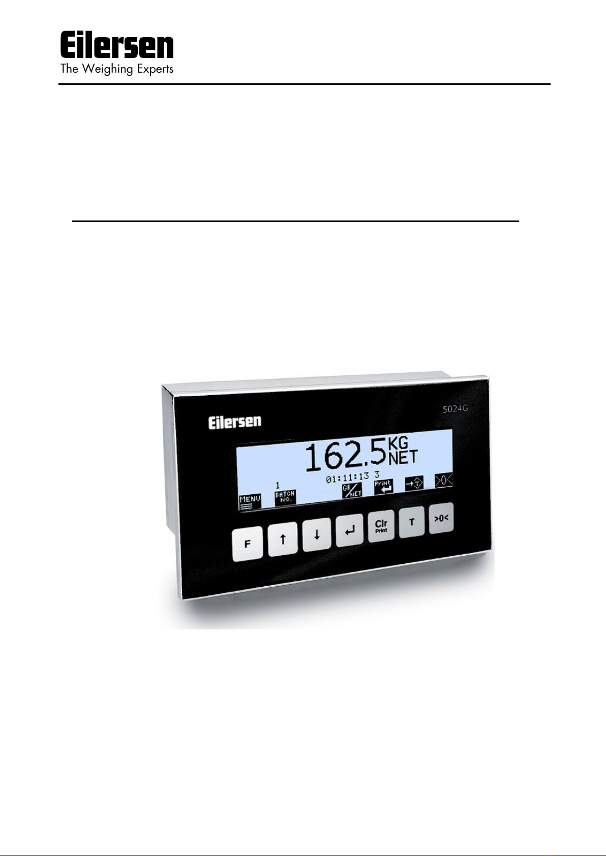
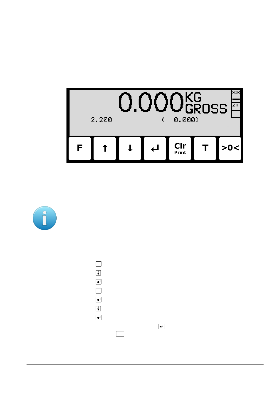
–Perform basic operations
When the system is installed and power-up sequence has ended the display will look like this:
6
WWW.EILERSEN.COM
Weight reading:
•The actual weight reading is displayed in large types.
•To the right of the weight reading, the unit is indicated, like KG, LB etc.
•Below the unit gross/net selection is indicated with GROSS or NET.
•If an error condition is present the weight reading will indicate the error, like UL, OL,
- 0080 –etc. Please see below in section Trouble shooting, page 29 for details on er-
ror codes and how to recover from various error situations.
Status indications:
•‘>0<’ in the upper right corner status field indicates that the actual gross weight is ze-
ro (within ± ¼ division).
•‘--’in the second status field indicates that the weight reading is steady/stable. If the
reading is unstable ‘~’ will be indicated.
•‘ZT’ in the third status field indicates that a zero tracking device is active, holding the
actual gross weight at zero.
•‘SP’ in the fourth status field if automatic dosing is running.
‘R’ in the fourth status field if registration is in progress.
•Above the key the actual setpoint (fine limit) is shown.
•Above the
Print
Clr
key the last registered weight is shown in parenthesis. Also above the
Print
Clr
key an “OK” icon is shown for a short period following every successful registra-
tion.
Please notice: The net weight is used to determine the state of the digital outputs during
dosing even when the gross weight is displayed.
Please see below how automatic dosing and digital outputs are used.
Please notice: If none of the icons directly above the keys are visible as shown in the
screen shot above, the keyboard is locked, since the Keyboard unlock length parameter
in the SETUP SYSTEM screen has been activated. As long as the keyboard is locked, no
keyboard actions will be available. Please see below in section - Unlock the keyboard,
page 11 on how to unlock the keyboard.
Keys/actions:
F
Invoke the MAIN menu.
Select the DOSING screen to enter the setpoints and start/stop of dosing.
7
WWW.EILERSEN.COM
Displays weight with enhanced resolution for 3 seconds. The “Dd/10”symbol
above the key will flash when enhanced resolution is shown.
Switch between Gross and Net reading.
Print
Not used.
T
Sets the net weight to zero and select Net reading.
>0<
Sets the gross weight to zero and select Gross reading.
–Perform automatic dosing
To perform an automatic dosing, follow this procedure:
1. The desired Coarse and Fine setpoints must be entered. Use the key in the NORMAL
screen to select the DOSING screen. Then use the DOSING screen to enter the desired
setpoints.
2. To start a new dosing select the “Action: START DOSING” using the or key in the
DOSING screen and then press the key. Alternately start a new dosing by activating
the digital START input.
3. This will zero the net weight (automatic tare) and activate the digital COARSE and FINE
dosing outputs.
4. During dosing the COARSE output is active as long as the net weight does not exceed the
COARSE limit. An active COARSE output indicates dosing should be done at high speed
for the first part of the dosing, followed by slow speed for the final part of the dosing
where the COARSE output is deactivated.
5. When the net weight (positive or negative) reaches the FINE setpoint (possibly adjusted
by the afterflow correction) the FINE output will be deactivated and dosing is stopped.
6. Hereafter the COARSE and FINE outputs will remain deactivated until a new dosing is
started.
7. The dosed amount is automatically registered after the entered registration period, if
the registration period is different from 0 ms. In this case a registration can be made by
activating the REGISTRATION input. The result of the last registration can be read in the
NORMAL screen.
8. Following a registration the totals are updated and a possible new afterflow correction
may be calculated.
9. An ongoing dosing can be stopped prior to reaching the setpoint, by selecting the “Ac-
tion: STOP DOSING” using the or key in the DOSING screen and then pressing the
key. An ongoing dosing is also aborted if the weighing range is exceeded or if a load
cell error occurs.
10. The weighing terminal is ready for start of a new dosing.
8
WWW.EILERSEN.COM
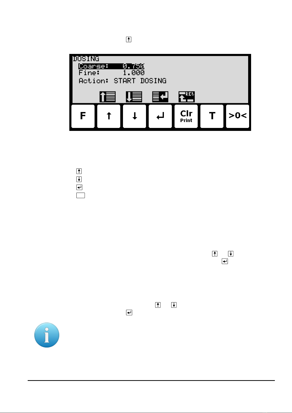
–Change setpoints for automatic dosing
In the MAIN screen press to select the DOSING screen, looking like this:
In this screen setpoints for dosing are shown and can be changed. It is also possible to
start/stop a dosing.
Keys/actions:
Select the previous setpoint/parameter.
Select the next setpoint/parameter.
Start entry of the selected setpoint or chooses the marked action.
Print
Clr
Return to the MAIN previous screen.
Setting Coarse and Fine limits
The COARSE and FINE setpoints used for automatic dosing must be specified in the DOSING
screen.
The COARSE limit is used to control the COARSE output indicating high speed dosing until the
COARSE setpoint is reached. The FINE limit is used to control the FINE output indicating the
desired amount to be dosed. The setpoints are changed by using and to select the de-
sired setpoint (“Coarse” or “Fine”) with the cursor, and then pressing to request change
of the setpoint.
Start/Stop of dosing
In addition to starting a dosing using the digital START input, a dosing can be started (or
stopped if a dosing is already in progress) using the keyboard in the DOSING screen.
A dosing is started or stopped by using and to select the “Action” parameter with the
cursor, and then pressing to request the indicated action (“START DOSING” or “STOP DOS-
ING”).
Please notice: Some other dosing parameters (such as registration period and afterflow cor-
rection) are configured in the DOSING PAR. screen.

9
WWW.EILERSEN.COM
–Change dosing parameters
From the menu system the DOSING PARAMETERS screen is selected:
In this screen dosing parameters such as registration period and afterflow correction are
shown and can be changed.
Change registration period
The registration period is the time from a dosing has finished to the actual amount dosed is
registered automatically. The registration period is entered in milliseconds (0 - 30000 ms).
The value should be set large enough to ensure no vibrations and a stable weight indication is
achieved before the automatic registration is performed. A value of 0 ms indicates that NO
automatic registration is performed, and that a registration must be made using the REGIS-
TRATION input (or the keyboard).
Change afterflow status
The afterflow status indicates whether afterflow correction is disabled (OFF), enabled using a
fixed correction (ON) or enabled using an automatically adjusted correction (AUTO).
Change afterflow correction
The actual afterflow correction used during dosing if enabled using the “Afterflow status” pa-
rameter (ON or AUTO), is the amount prior to the net weight reaching the FINE limit, where
the dosing is assumed to be completed and the FINE and COARSE outputs are deactivated.
The “Afterflow” parameter indicates the actual correction.
Please notice: The “Afterflow” parameter is not used if afterflow correction is disabled by
setting the “Afterflow status” parameter to OFF.
Please notice: The “Afterflow” parameter can be changed automatically after each dosing if
afterflow correction is performed automatically by setting the “Afterflow status” parameter
to AUTO.

10
WWW.EILERSEN.COM
–Reading totals
In the MAIN screen
F
is pressed to select the TOTALS screen from the menu:
In this screen the totals are shown. Whenever a registration is performed the total weight is
updated with the registered amount and the total count is incremented.
Reset of totals
Totals are reset by pressing
F
to show the TOTALS menu, where the ”RESET TOTALS” item is
selected with the cursor using the and keys and then pressing the key.
Please notice: Reset of totals can NOT be undone.
–Operate the menu system
The installation and service of the system is operated by a series of menus and screens.
Please see below in section Appendix C –Screen overview, page 35, for an overview on all
screens. When using setup and maintenance screens these keys are used:
F
Select a menu depending on the actual screen.
Increase a value, select previous parameter or move cursor up in a menu.
Decrease a value, select next parameter or move cursor down in a menu.
Select entry or accept of a value, or select an action from a menu.
Print
Clr
Return to previous screen. Exit menu without action.
Please notice: Parameters cannot be changed and actions not performed when the system is
powered on. Before such operations are possible the parameters must be unlocked as ex-
plain below in section - Unlock for parameter update, page 11.
–Set date and time
It is possible to set the date and/or time of the internal clock by use of the SETUP menu. To
set date and/or time from the SETUP screen perform the following:
F
Press once to select the SETUP menu.
Press several times to select the “SET DATE” or “SET TIME” entry from the SET-
UP menu.
Press once to start entry of the selected parameter (date or time).
11
WWW.EILERSEN.COM
- Unlock the keyboard
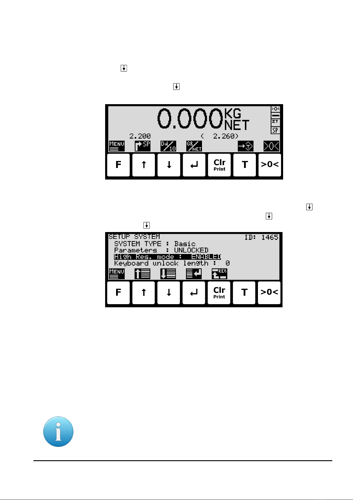
The terminal is equipped with a keyboard lock feature, which can be enabled or disabled us-
ing the Keyboard unlock length parameter in the SYSTEM screen as described below. If the
keyboard lock is disabled, then the keyboard functions will always be active. If the keyboard
lock is enabled, and the terminal is in the NORMAL screen without any key activation for 10
minutes (or directly after power-on), the keyboard will automatically lock. When the key-
board is locked, the NORMAL screen will appear as follows without any icons above the keys:
To unlock the keyboard:
•Press any key to start the keyboard unlock sequence.
•Press the indicated keys one at a time until the required sequence (specified by the
Keyboard unlock length parameter) is completed without error.
Please notice: This feature is disabled by setting the Keyboard unlock length parameter in
the SYSTEM screen to 0. Any other value specifies the length of the key sequence that must
be pressed correctly to unlock a locked keyboard.
- Unlock for parameter update
Parameters cannot be changed and actions not performed when the system is powered on.
Before such operations are possible the parameters must be unlocked:
•Press
F
to invoke the menu system.
•Press to highlight the SERVICE MODE menu item.
•Press to select the SETUP screen.
•Press
F
to invoke the menu where the SYSTEM menu item is highlighted.
•Press to select the SYSTEM screen.
•Press to highlight the Parameters entry.
•Press to select the ENTER UNLOCK PARAM parameter entry.
•Enter the password 1357 and press . Parameters are now unlocked and can be
changed. Press
Print
Clr
once to return to the SETUP screen or twice to return to the
NORMAL screen. Please see below in section –Enter values, page 12, for details on
how to enter values (like the password).

12
WWW.EILERSEN.COM
The status automatically returns to LOCKED after 5 minutes without keyboard activity in
NORMAL screen or when the terminal is power-cycled.
–Enter values
Perform these steps to enter a new parameter value:
•Unlock parameters as described in the above section.
•Use the menus to select the screen where the value is displayed.
•Use and/or to highlight the parameter.
•Press to start entering a new value.
Entry using selection list
Some parameters (such as resolution and decimal point position) are entered using a selec-
tion list. When change of this type of parameter is requested, a special pull-down menu will
appear with a list of possible values as shown:
The keys can be used as follows:
F
Move the cursor down in this selection list.
Move the cursor up in this selection list.
Move the cursor down in this selection list.
Accept the selected/marked value as the new desired value.
Print
Clr
Abort the entry without change of parameter. This can also be done by selecting
the “CANCEL” entry form the selection list.
Example - Changing resolution from 0.050 to 0.010:
The screen shown above appears once change of resolution is requested from the SETUP
WEIGHING screen by moving the cursor using and so the Resolution parameter is se-
lected and then pressing . In order to change the “Resolution” parameter to 0.010 perform
the following:
•Press and/or repeatedly until 0.010 is selected in the list.
•Press to accept the selection.
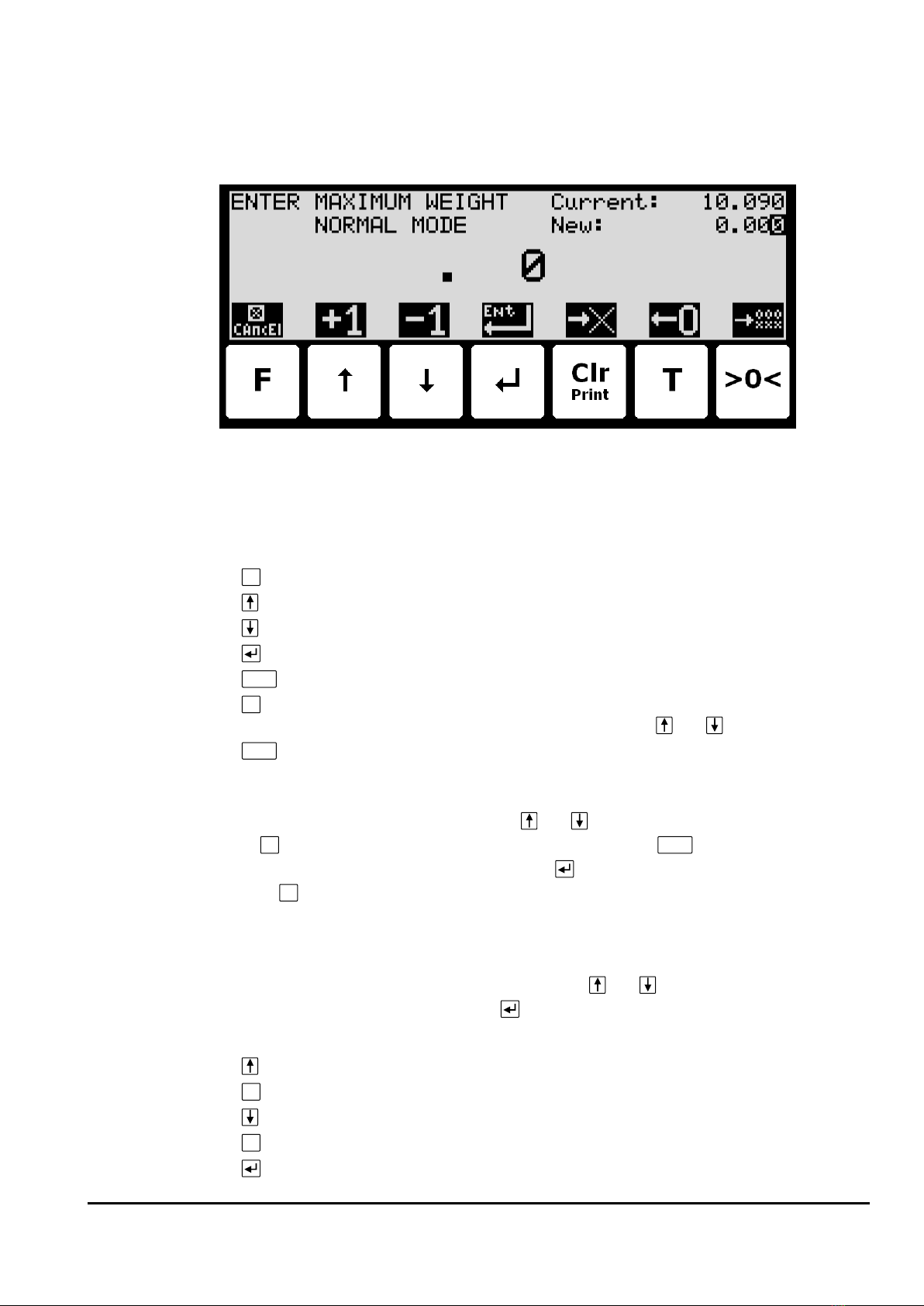
Entry of numbers
Some parameters (such as minimum and maximum weight of the weighing range) are en-
tered using a data entry screen. When change of this type of parameter is requested, a data
13
WWW.EILERSEN.COM
entry screen will appear. Please note the layout of the data entry screen may vary slightly
depending on the actual parameter to be changed. The data entry screen could look as
shown:
The actual parameter changed is indicated in the upper left part of the display. The current
parameter value and the currently entered value is shown in the upper right part of the dis-
play. The currently entered value is also shown in the middle of the display in large font.
The keys can be used as follows:
F
Abort the entry without change of parameter.
Increase the value of the digit currently being entered (digit to the right).
Decrease the value of the digit currently being entered (digit to the right).
Accept the entered value as the new desired value.
Clr
Delete rightmost digit and moves all remaining digits one position to the right.
T
Move digits one position to the left and inserts a zero on the rightmost position.
This new digit can subsequently be changed using and .
>0<
Clears all entered digits setting them to zero as if the data entry screen has just
been entered.
When entering a value the digits are entered left to right. This means that leftmost digit is
entered first. The active digit is changed by and . When the correct value is entered
press
T
to advance to the next digit. If an error is made, press
Clr
to return to the previous
digit. When the complete value is entered press to accept it. To abort without any chang-
es press
F
.
Example - Changing maximum weight from 10.000 to 10.090:
The screen shown above appears once change of maximum weight is requested from the
SETUP WEIGHING screen by moving the cursor using and so the “Maximum” weight
parameter is selected and then pressing .
In order to change the “Maximum” weight parameter to 10.090 perform the following:
Press once until ” . 1” is shown in the display.
T
Press three times until ” 1.000” is shown in the display.
Press once until ” 1.009” is shown in the display.
T
Press once until ” 10.090” is shown in the display.
Press to accept ” 10.090” as the new desired value.
14
WWW.EILERSEN.COM
Example - Changing minimum weight from -1.000 to -0.090:
A similar screen to the screen shown above appears once change of minimum weight is re-
quested from the SETUP WEIGHING screen by moving the cursor using and so the
“Minimum” weight parameter is selected and then pressing .
In order to change the “Minimum” weight parameter to -0.090 perform these steps:
Press once until ”-. 9” is shown in the display.
T
Press once until ”-. 90” is shown in the display.
Press to accept ”-0.090”as the new desired value.
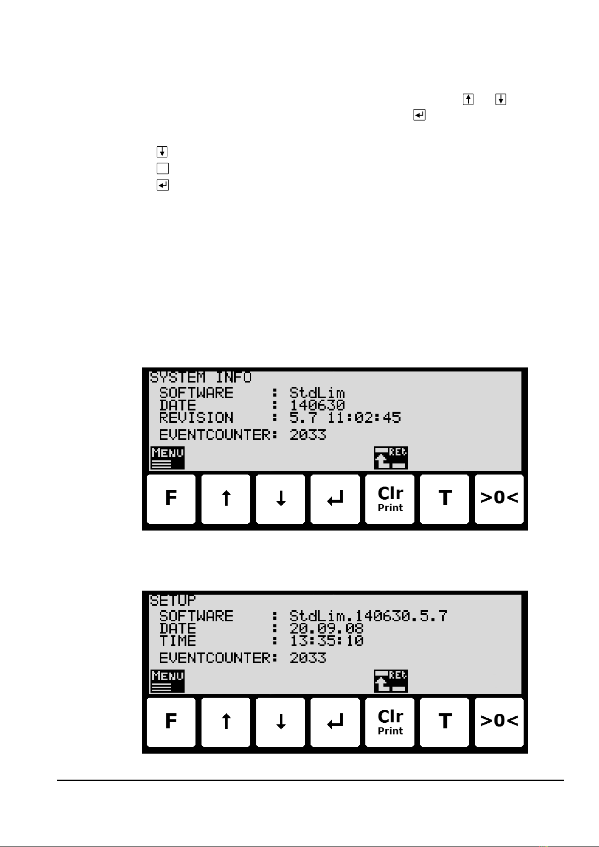
–Check the software version
The software version can be checked during the power-on sequence or in the SYSTEM INFO
or SETUP screen. When power is applied to the system, the following will happen:
•The display will show the logo for 5 seconds.
•The display will show the software version (software name, date and revision).
•The weighing terminal is ready and enters the NORMAL screen.
Select the SYSTEM INFO screen to read the software version (software name, date and revi-
sion):
The SETUP screen also shows the software version (software name, date and revision):

15
WWW.EILERSEN.COM
–Activate Intelligent Setup
With reference to installation of the weighing system, the weighing terminal has a build-in in-
telligent setup feature, that automatically comes with suggestions to configuration of the
weighing technical parameters. If this feature is to be used, it can be activated/started by
performing the following:
•From the NORMAL screen press
F
to activate the menu system, and select SERVICE
MODE menu item to enter the SETUP screen.
•From the SETUP screen press
F
to activate the menu system, and select SYSTEM
menu item to enter the SETUP SYSTEM screen.
•Unlock the parameters for change by entering the password as described earlier.
•Press
F
to activate the menu system, and select INTELLIGENT SETUP menu item to
enter the INTELLIGENT SETUP screen.
•NOTE: Refer to the separate ’Intelligent Setup’manual for further information re-
garding this feature.
–Set up the load cell configuration
To set up the load cell communication protocol type, number of load cells and supports
please follow these steps:
•From the NORMAL screen select the SERVICE MODE menu item to reach the SETUP
screen.
•From the SETUP screen select the WEIGHING menu item to reach the SETUP WEIGH-
ING screen.
•From the SETUP WEIGHING screen select the LOAD CELLS menu item to reach the
Load cell parameters screen.
•Enter the correct values for load cell communication protocol type, number of load
cells and supports, or detect this automatically from the menu.
•Please notice: The terminal must be power-cycled and the load cells must be con-
nected before changes take effect!

16
WWW.EILERSEN.COM
Load cell communication protocol type
The weighing terminal can be connected to and communicate with different kinds of load
cells from Eilersen Electric. Depending on load cells and how they are connected, the weigh-
ing terminal can communicate with the load cells using the following load cell protocols:
•2010: Load cells connected using MCE2010 (StdBB protocol).
•401x: Load cells connected using 4015 connection module.
•4x40-StdBB: Load cells connected using 4x40 unit (StdBB protocol).
•4x40-StdLC: Load cells connected using 4x40 unit (StdLC protocol).
Please notice: Therefore, selection of protocol type must also take into consideration, the
software version in the used load cell modules (MCE2010/4x40).
Number of load cells
The weighing terminal can be connected to a maximum of 16 load cells.
Number of supports
The actual number of supporting points must be in the range 1-16. Note that it is the total
number of supporting points including corners supported by load cells. As an example, the
Supports parameter should be 3 in a system consisting of a three legged tank.
–Detect the load cell configuration
To detect load cell protocol, number of load cells and number of supports the following is
performed:
•Use the screens and menu system to select the LOAD CELLS screen.
•Press
F
to invoke the LOAD CELL PAR. menu.
•Press to select the DETECT LOAD CELL PROTOCOL or DETECT NUMBER OF LOAD
CELLS menu item.
•Press to perform the selected action, and follow the instructions in the following
screens.
Please notice:The load cells must be connected for the above detection to work correctly.
17
WWW.EILERSEN.COM
–Configure the weighing ranges
The weighing terminal is equipped with three different weighing range modes that specify
the weighing range used for:
NORMAL: Weight readings during normal display reading.
CALIBRATION: Weight readings during calibration and enhanced/high resolution weight
display.
PROTOCOL: Weight readings transferred using communication protocols.
Using the screens and menu system as described above in section Operate the menu system,
page 10 select the WEIGHING screen to configure the three weighing ranges:
–Perform coarse taring
To coarse tare the system follow these steps:
•Use the screens and menu system to select the COARSETARE screen.
•Press
F
to invoke the COARSETARE menu.
•Press to select the PERFORM COARSETARE menu item.
•Press to perform a coarse tare.
Please notice: Coarse taring should only be done when the system is empty!
18
WWW.EILERSEN.COM
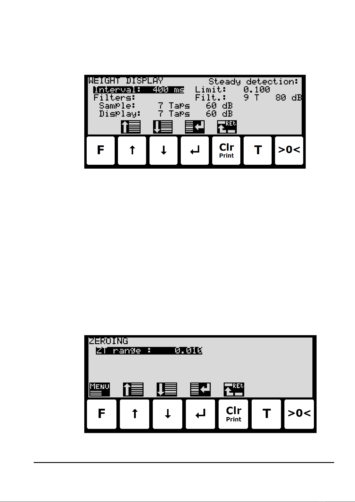
–Configure display, filtering and stability requirement
To configure display update rate, filtering and stability requirement, select the WEIGHT DIS-
PLAY screen:
Interval
The interval between each update of the weight indication is entered in milliseconds (ms). A
small value results in fast update of the display reading, while a larger value results in a more
steady display reading. A good starting/default value is 400 ms.
Filters
Two types of filters can be applied: A filter on each sampling from the load cell and/or a filter
on each display weight reading update. The sampling frequency depends on the load cell
communication formats and number of load cells and the weight display reading update rate,
as described below in section Appendix D –Filters, page 35.
Steady/stability detection
The weight is considered stable when the readings are within the limit entered here. The
weight ready used for steady detection is filtered with the filter entered here. The steady de-
tection filter works like the display filter.
–Configure zero tracking
To configure the zero tracking range, select the ZEROING screen:
19
WWW.EILERSEN.COM
–Change reading to high resolution mode
High resolution mode changes the display reading to the enhanced resolution entered as the
CALI weighing range. This can be done in two ways:
•Press in the NORMAL screen. This will select high resolution mode for 3 seconds
(assuming the High res. mode parameter in the SETUP SYSTEM screen is set to DISA-
BLED). The symbol above will flash while high resolution is active.
•In the SETUP SYSTEM screen, change the High res. mode parameter to ENABLED
(this can only be done when parameters are unlocked). Now when pressing in the
NORMAL screen high resolution mode will be selected until is pressed again. The
symbol above will flash while high resolution is active.
–Perform load check
When checking the weight reading please observe these points:
•Use different loads; small and near the maximum load.
•Do not place the full load on the corners.
•Use approx. 1/3 of full load to check the corners.
•Use High resolution mode for a more accurate reading.
–Perform corner calibration
Please notice: Corner calibration is only necessary in system with more than one load cell.
Corner calibration is not possible when there are more supports than load cells and should
only be used in weighing systems where system mechanics shows non ideal behavior regard-
ing load in the corners.
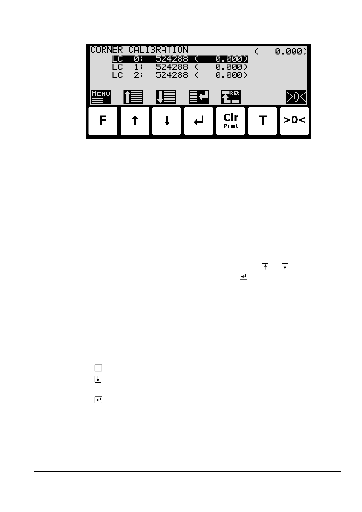
20
WWW.EILERSEN.COM
Use the CORNER CALIBRATION screen to perform a corner calibration if necessary.
In this screen corner calibration parameters such as corner calibration factor, and actual load
on corresponding load cell is shown on one line for each load cell. The actual gross weight is
shown in the upper right corner. This makes it possible to manually enter the corner calibra-
tion factor for each load cell. From the CORNER CAL. menu it is possible to select the COR-
NER CAL. PROC. screen for corner calibration of the system. It is also possible to reset the
corner calibration factors to default values from the menu. A cursor (inverted text) indicates
the currently selected parameter.
Corner calibration factor
The corner calibration factors can be changed/specified in the CORNER CALIBRATION screen
by performing a calibration of the corners by switching to the CORNER CAL. PROC. screen as
described below or by manually entering a new factor.
The corner calibration factors can be manually changed by using and to select the de-
sired load cell/corner with the cursor, and then pressing to request change of the selected
corner calibration FACTOR parameter. This is useful when a previous calibration must be re-
established. Note that this is only possible, if the calibration factor for this previous calibra-
tion is known. The standard calibration factor is 524288. If this value is changed 1% (up or
down), the signal from that load cell/corner will also change 1% (up or down).
Reset corner calibration factors
It is possible to reset the corner calibration factors to default values (524288) by using the
CORNER CAL. menu. To perform a reset of corner calibration factors from the CORNER CALI-
BRATION screen use these steps:
F
Press once to select the CORNER CAL. menu.
Press once to select the “RESET CORNER CAL. FACTORS” entry from the CORNER
CAL. menu.
Press once to perform the reset of the corner calibration factors.
Corner calibration procedure
It is possible to perform an automatic corner calibration of the system by selecting the COR-
NER CALIBRATION PROCEDURE screen from the CORNER CAL. menu.
Other manuals for 5024G
3
Table of contents
Popular Accessories manuals by other brands


NATURE & DECOUVERTES
NATURE & DECOUVERTES 60158450 manual

A-oneTech
A-oneTech AIR HALO user manual

Omnicom
Omnicom LLS-Ex 5 manual

PCB Piezotronics
PCB Piezotronics IMI SENSORS HT640B71 Installation and operating manual

Xylem
Xylem WTW NiCaVis 705 IQ TS operating manual

Renishaw
Renishaw RMP60 installation guide


