manuals.online logo
Brands
  1. Home
  2. •
  3. Brands
  4. •
  5. Renishaw
  6. •
  7. Accessories
  8. •
  9. Renishaw RMP60 User manual

Renishaw RMP60 User manual

RMP60 radio machine probe
Installation guide
H-5742-8504-02-D
Renishaw part no: H-5742-8504-02-D
First issued 11 2012
Issued: 05.2023
© 2012-2023 Renishaw plc. All rights reserved.
This document may not be copied or reproduced in whole or in part, or transferred to any other media
or language, by any means, without the prior written permission of Renishaw.
Renishaw plc. Registered in England and Wales. Company no: 1106260. Registered office: New Mills,
Wotton-under-Edge, Gloucestershire, GL12 8JR, UK.
Compliance information for this product is available by scanning the QR code or visiting
www.renishaw.com/mtpdoc
i
Contents
Before you begin .............................................................1.1
Disclaimer .................................................................1.1
Trade marks................................................................1.1
Warranty ..................................................................1.1
Changes to equipment .......................................................1.1
CNC machines .............................................................1.2
Care of the probe ...........................................................1.2
Patents ...................................................................1.2
Intended use ...............................................................1.3
Safety ....................................................................1.3
RMP60 basics ................................................................2.1
Introduction ................................................................2.1
Getting started ...........................................................2.1
System interface..........................................................2.2
Trigger Logic™ ...........................................................2.2
Probe modes...............................................................2.2
Configurable settings.........................................................2.3
Switch-on / switch-off methods...............................................2.3
Enhanced trigger filter .....................................................2.5
Hibernation mode.........................................................2.5
Multiple probe mode.......................................................2.5
Acquisition mode .........................................................2.6
RMP60 dimensions ..........................................................2.7
RMP60 specification .........................................................2.8
Typical battery life.........................................................2.9
RMP60 installation guide
ii
Contents
System installation ...........................................................3.1
Installing the RMP60 with an RMI or RMI-Q .......................................3.1
Operating envelope .......................................................3.1
Positioning the RMP60 and RMI or RMI-Q ........................................3.2
Performance envelope .....................................................3.2
Preparing the RMP60 for use ..................................................3.3
Fitting the stylus ..........................................................3.3
Installing the batteries .....................................................3.5
Mounting the probe on a shank ..............................................3.6
Stylus on-centre adjustment.................................................3.7
Stylus trigger force and adjustment..............................................3.8
Calibrating the RMP60 .......................................................3.9
Why calibrate a probe? ....................................................3.9
Calibrating in a bored hole or on a turned diameter...............................3.9
Calibrating in a ring gauge or on a datum sphere ................................3.9
Calibrating the probe length ................................................3.10
Trigger Logic™ ...............................................................4.1
Reviewing the probe settings ..................................................4.1
Multiple probe mode settings ..................................................4.2
Probe settings record ........................................................4.3
Changing the probe settings ...................................................4.4
RMP60 – RMI partnership.....................................................4.7
RMP60 – RMI-Q partnership...................................................4.8
Operating mode.............................................................4.9
Maintenance .................................................................5.1
Maintenance ...............................................................5.1
Cleaning the probe ..........................................................5.1
Changing the batteries .......................................................5.2
Diaphragm replacement ......................................................5.4
RMP60M system .............................................................6.1
RMP60M system............................................................6.1
RMP60M dimensions ........................................................6.2
RMP60M screw torque values. . . . . . . . . . . . . . . . . . . . . . . . . . . . . . . . . . . . . . . . . . . . . . . . . . 6.2
Fault-finding .................................................................7.1
Parts list .....................................................................8.1
1.1
Before you begin
see Section 1, “Before you begin”
Disclaimer
WHILE CONSIDERABLE EFFORT WAS MADE TO VERIFY THE ACCURACY OF THIS DOCUMENT
AT PUBLICATION, ALL WARRANTIES, CONDITIONS, REPRESENTATIONS AND LIABILITY,
HOWSOEVER ARISING, ARE EXCLUDED TO THE EXTENT PERMITTED BY LAW.
RENISHAW RESERVES THE RIGHT TO MAKE CHANGES TO THIS DOCUMENT AND TO THE
EQUIPMENT, AND/OR SOFTWARE AND THE SPECIFICATION DESCRIBED HEREIN WITHOUT
OBLIGATION TO PROVIDE NOTICE OF SUCH CHANGES.
Trade marks
RENISHAW® and the probe symbol are registered trade marks of Renishaw plc. Renishaw
product names, designations and the mark ‘apply innovation’ are trade marks of Renishaw plc or its
subsidiaries.
Google Play and the Google Play logo are trademarks of Google LLC.
Apple and the Apple logo are trademarks of Apple Inc., registered in the U.S. and other countries.
AppStore is a service mark of Apple Inc., registered in the U.S. and other countries.
Other brand, product or company names are trade marks of their respective owners.
Warranty
Unless you and Renishaw have agreed and signed a separate written agreement, the equipment
and/or software are sold subject to the Renishaw Standard Terms and Conditions supplied with such
equipment and/or software, or available on request from your local Renishaw office.
Renishaw warrants its equipment and software for a limited period (as set out in the Standard Terms
and Conditions), provided that they are installed and used exactly as defined in associated Renishaw
documentation. You should consult these Standard Terms and Conditions to find out the full details of
your warranty.
Equipment and/or software purchased by you from a third-party supplier is subject to separate terms
and conditions supplied with such equipment and/or software. You should contact your third-party
supplier for details.
Changes to equipment
Renishaw reserves the right to change equipment specifications without notice.
RMP60 installation guide
1.2
Before you begin
CN 100416216
CN 100466003
CN 101476859
CN 101482402
EP 1425550
EP 1457786
EP 1477767
EP 1576560
EP 1613921
EP 1804020
EP 1931936
EP 2216761
IN 215787
IN 234921
IN 8707/DELNP/2008
WO 2004/057552
JP 4237051
JP 4575781
JP 4852411
JP 5238749
JP 5390719
KR 1001244
TW I333052
US 6941671
US 7285935
US 7316077
US 7486195
US 7665219
US 7821420
US 9140547
CNC machines
CNC machine tools must always be operated by fully trained personnel in accordance with the
manufacturer’s instructions.
Care of the probe
Keep system components clean and treat the probe as a precision tool.
Patents
Features of the RMP60, and other similar Renishaw products, are the subject of one or more of the
following patents and/or patent applications:
1.3
Before you begin
Intended use
The RMP60 is a radio spindle probe that enables automated workpiece inspection and job set-up on
multi-tasking machines, machining centres and gantry machining centres.
Safety
Information to the user
This product is supplied with non-rechargeable batteries that do not contain lithium. For specific battery
operating, safety and disposal guidelines refer to the battery manufacturers’ literature.
• Do not attempt to recharge the batteries.
• Replace the batteries only with the specified type.
• Do not mix new and used batteries in the product.
• Do not mix different types or brands of batteries in the product.
• Ensure that all batteries are inserted with the correct polarity in accordance with the instructions in
this manual and indicated on the product.
• Do not store the batteries in direct sunlight.
• Do not expose the batteries to water.
• Do not expose the batteries to heat or dispose of batteries in a fire.
• Avoid forced discharge of the batteries.
• Do not short circuit the batteries.
• Do not disassemble, apply excessive pressure, pierce, deform or subject the batteries to impact
• Do not swallow the batteries.
• Keep the batteries out of the reach of children.
• If the batteries are swollen or damaged do not use them in the product and exercise caution when
handling them.
• Dispose of waste batteries in accordance with your local environmental and safety laws.
Ensure that you comply with international and national battery transport regulations when transporting
batteries or this product with the batteries inserted. To reduce the risk of shipment delays, should you need
to return this product to Renishaw for any reason, do not return any batteries.
Information to the machine supplier/installer
It is the machine supplier’s responsibility to ensure that the user is made aware of any hazards
involved in operation, including those mentioned in Renishaw product literature, and to ensure that
adequate guards and safety interlocks are provided.
If the probe fails, the probe signal may falsely indicate a probe seated condition. Do not rely on probe
signals to halt the movement of the machine.
RMP60 installation guide
1.4
Before you begin
Information to the equipment installer
All Renishaw equipment is designed to comply with the relevant EU and FCC regulatory requirements.
It is the responsibility of the equipment installer to ensure that the following guidelines are adhered to,
in order for the product to function in accordance with these regulations:
• any interface MUST be installed in a position away from any potential sources of electrical noise,
(for example power transformers, servo drives):
• all 0V/ground connections should be connected to the machine “star point” (the “star point” is a
single point return for all equipment ground and screen cables).This is very important and failure to
adhere to this can cause a potential difference between grounds;
• all screens must be connected as outlined in the user instructions;
• cables must not be routed alongside high current sources (for example, motor power supply
cables), or be near high-speed data lines;
• cable lengths should always be kept to a minimum.
Equipment operation
If this equipment is used in a manner not specified by the manufacturer, the protection provided by the
equipment may be impaired.
see Section 2, “RMP60 basics”
2.1
RMP60 basics
Introduction
The RMP60 probe forms part of Renishaw’s family of radio transmission part probing systems. It is
ideally suited to large machining centres or where line-of-sight between probe and receiver is difficult
to achieve.
Featuring an integrated probe module, the RMP60 delivers exceptional robustness and generous
overtravel.
The RMP60 complies with worldwide standards and operates in the 2.4 GHz band. It delivers
interference-free transmission through the use of hybrid FHSS (frequency hopping spread spectrum)
technology, which allows many systems to operate in the same machine shop without risk of
interference.
The RMP60 can be used alone or form part of a larger system comprised of multiple radio spindle
probes and/or tool setters to function with a single interface.
All RMP60 settings are configured using “Trigger Logic™”. This technique enables the user to review
and subsequently change probe settings by deflecting the stylus whilst observing the LED display.
Configurable settings are:
• Switch-on / switch-off method
• Trigger filter setting
• Hibernation setting*
• Multiple probe mode
Getting started
Three multicolour probe LEDs provide visual indication of selected probe settings.
For example:
• Switch-on and switch-off methods
• Probe status – triggered or seated
• Battery condition
Batteries are inserted or removed as shown (for more information, see page 3.5, “Installing the
batteries”).
On insertion of batteries, the LEDs will begin to flash, starting with a LED check (for more information,
see page 4.1, “Reviewing the probe settings”,).
see Section 2, “RMP60 basics”
RMP60 installation guide
2.2
RMP60 basics
System interface
The radio machine interface (RMI-Q) is an integrated interface/receiver used to communicate between
the RMP60 probe and the machine controller.For more details, refer to the RMI-Q radio machine
interface installation guide (Renishaw part no. H-5687-8504).
RMP60 is also compatible with the older radio machine interface (RMI) integrated interface/receiver.
For more details, refer to the RMI radio machine interface installation guide (Renishaw part no.
H-4113-8554).
Trigger Logic™
Trigger Logic™ (for more information, see page 4.1, “Reviewing the probe settings”) is a method
that allows the user to view and select all available mode settings in order to customise a probe to suit
a specific application. Trigger Logic is activated by battery insertion and uses a sequence of stylus
deflections (triggering) to systematically lead the user through the available choices, observed via the
LED display, to allow selection of the required mode options.
A Probe Setup app is available that simplifies this process with clear, interactive instructions and
informative videos and is available for download on the App Store and Google Play.
or
Current probe settings can also be reviewed by simply removing the batteries for a minimum
of 5 seconds, and then replacing them to activate the Trigger Logic review sequence (for more
information, see page 4.1, “Reviewing the probe settings”).
Probe modes
The RMP60 probe can be set in one of three modes:
Standby mode –Probe is waiting for a switch-on signal.
NOTE: The RMP60 will enter “hibernation mode” should the system interface be powered off or out
of range for a period of 30 seconds. This is a congurable setting.
Operational mode –When activated by one of the switch-on methods, the probe is switched on and
ready for use.
Configuration mode – Ready to change the probe settings using Trigger Logic.
2.3
RMP60 basics
Configurable settings
Switch-on / switch-off methods
The following switch-on / switch-off options are user-configurable.
• Radio on / Radio off
• Radio on / Timer off
• Spin on / Spin off
• Spin on / Timer off
• Shank switch on / Shank switch off
RMP60 installation guide
2.4
RMP60 basics
RMP60 switch-on method
Switch-on options are configurable
RMP60 switch-off method
Switch-off options are configurable
Switch-on time
Radio on
Radio switch on is commanded by
machine input.
Radio off
Radio switch off is commanded by
machine input. A timer automatically
switches the probe off 90 minutes
after the last trigger if it is not turned
off by machine input.
Timer off (timeout)
Timeout will occur 12, 33 or 134
seconds (user configurable) after the
last probe trigger or reseat.
1 second (see notes
below).
Spin on
Spin at 500 r/min for 1 second
minimum.
Spin off
Spin at 500 r/min for 1 second
minimum. A timer automatically
switches the probe off 90 minutes
after the last trigger if it is not spun.
Timer off (timeout)
Timeout will occur 12, 33 or 134
seconds (user configurable) after the
last probe trigger or reseat.
1 second maximum
(see notes below).
Shank switch on Shank switch off 1 second maximum
NOTES:
In “radio on mode”, the switch-on time is user selectable “fast” or “standard” when using RMI-Q
(selection is made in RMI-Q). Otherwise, the switch-on time is 1second.
For more information on the user selectable switch-on time when operating with RMI-Q, see the RMI-Q
radio machine interface installation guide (Renishaw part no. H-5687-8504).
User selectable switch-on time is not available with the RMI.
In “radio on mode”, the switch-on time assumes a good radio communication link. In a poor radio
frequency (RF) environment this may rise to a maximum of 3seconds.
In “spin on mode”, the 1 second starts from the moment the spindle reaches 500 r/min.
The RMP60 must be on for a minimum of 1second before being switched off.
2.5
RMP60 basics
Enhanced trigger filter
Probes subjected to high levels of vibration or shock loads may output probe trigger signals without
having contacted any surface. The enhanced trigger filter improves the probe’s resistance to these
effects.
When the filter is enabled, a constant nominal 10 ms or 20 ms delay is introduced to the probe output.
It may be necessary to reduce the probe approach speed to allow for the increased stylus overtravel
during the extended time delay.
Factory set to OFF.
Hibernation mode
Only applicable to “radio-on mode”.
When the RMP60 is in standby and the RMI or RMI-Q is powered off or out of range, the probe enters
hibernation; a low power mode designed to save battery life. The probe ‘wakes’ from hibernation to
periodically check for its partnered RMI or RMI-Q.
The ‘wake-up’ frequency can be set to 30seconds, 5 seconds or set to off; the probe never goes into
hibernation.
Factory set to 30 seconds.
Multiple probe mode
The RMP60 can be configured, using Trigger Logic, to allow multiple radio probes in “spin on / spin off”
or “shank on / shank off” to be used with a single RMI or RMI-Q.
Up to four RMP60s can be used with a single RMI-Q in “radio on / radio off mode”. For further
details of this functionality, see the RMI-Q radio machine interface installation guide (Renishaw part no.
H-5687-8504).
NOTES:
“Multiple probe mode” is a function of the RMP60. As such, the option will not appear when the
“radioon” option has been selected.
RMP60 probes which are set to “multiple probe mode on” can coexist alongside any number of
RMP60 probes set to “multiple probe mode off”.
To allow multiple radio probes to work in close proximity, and with a single RMI or RMI-Q, 16choices
of “mode on” colours are available, each representing a different machine tool installation. (for more
information, see page 4.2, “Multiple probe mode settings”).
All probes operating with a single RMI or RMI-Q must be set to the same “mode on” colour choice;
any multiple probes located on adjacent machines must all be set to an alternative “mode on” colour
choice.
NOTE: Each probe per “mode on” colour choice must be partnered with the RMI or RMI-Q. By
conguring multiple probes to a single “mode on” colour choice, all probes using this “mode on”
colour choice will have the same identity.
RMP60 installation guide
2.6
RMP60 basics
The probe to be partnered is partnered after selecting the “multiple probe mode setting” and
choosing the “mode on” option. (for more information, see page 4.4, “Changing the probe settings”).
There is no limit to the number of probes that can be used with a single RMI or RMI-Q so long as they
all have the same “mode on” colour choice. All RMP60 probes are factory set to “mode off”.
The addition of any further probe(s) into a single probe installation will require that all probes are
reconfigured to the same “mode on” colour choice and that one of the probes is then repartnered with
the RMI or RMI-Q.
The addition of any further probe(s), or replacements, into a multi-probe installation can be achieved
through the reconfiguration of the probe to the same “mode on” colour choice.
Acquisition mode
System set-up is achieved using Trigger Logic and powering-on the RMI or RMI-Q. Alternatively
“ReniKey” may be used (see notes below).
Partnering is only required during initial system set-up. Further partnering is only required if the
RMP60, RMI or RMI-Q is changed.
NOTES:
Systems using the RMI-Q can be partnered with up to four RMP60s manually. Alternatively, partnering
to an RMI-Q, can be achieved by using ReniKey; a Renishaw machine macro cycle which does not
require the RMI-Q to be power cycled.
For more information or to download ReniKey free of charge visit:
www.renishaw.com/mtpsupport/renikey
Partnering by ReniKey is not available for the RMI.
Partnering will not be lost by reconfiguration of probe settings or when changing batteries, except
where “multiple probe mode” is selected.
Partnering can take place anywhere within the operating envelope.
2.7
RMP60 basics
RMP60 dimensions
Dimensions given in mm (in)
A range of probe-ready shanks
are available from Renishaw
50 (1.97) 19 (0.75) Battery cassette
Shank switch (optional)
18°
18°
Ø63 (Ø2.48)
76 (2.99)
M4 stylus
Probe status LED
XY overtravel
Transmission window
Stylus overtravel limits
Stylus length ±X/±Y Z
50 (1.97) 21 (0.82) 11 (0.43)
100 (3.94) 37 (1.45) 11 (0.43)
RMP60 installation guide
2.8
RMP60 basics
RMP60 specification
Principal application Workpiece inspection and job set-up on multi-tasking machines,
machining centres and gantry machining centres.
Dimensions Length
Diameter
76 mm (2.99 in)
63 mm (2.48 in)
Weight (without shank) With batteries
Without batteries
876 g (30.90 oz)
826 g (29.14 oz)
Transmission type Frequency hopping spread spectrum (FHSS) radio
Radio frequency 2400 MHz to 2483.5 MHz
Switch-on methods Radio M-code, spin on or shank switch
Switch-off methods Radio M-code, timer, spin off or shank switch
Spindle speed (maximum) 1000 r/min
Operating range Up to 15 m (49.2 ft)
Receiver / interface RMI or RMI-Q combined interface and receiver unit
Sense directions ±X, ±Y, +Z
Unidirectional repeatability 1.00 µm (40 µin) 2s1
Stylus trigger force 2 3
Factory setting:
XY low force
XY high force
+Z
0.75 N, 76 gf (2.70 ozf)
1.40 N, 143 gf (5.04 ozf)
5.30 N, 540 gf (19.06 ozf)
Maximum setting:
XY low force
XY high force
+Z
2.00 N, 204 gf (7.19 ozf)
3.50 N, 357 gf (12.59 ozf)
14.00 N, 1428 gf (50.36 ozf)
Minimum setting:
XY low force
XY high force
+Z
0.50 N, 51 gf (1.80 ozf)
0.90 N, 92 gf (3.24 ozf)
3.50 N, 357 gf (12.59 ozf)
Stylus overtravel XY plane
+Z plane
±18°
11 mm (0.43 in)
1 Performance specification is tested at a standard test velocity of 480 mm/min (18.9 in/min) with a 50 mm stylus
Significantly higher velocity is possible depending on application requirements.
2 Trigger force, which is critical in some applications, is the force exerted on the component by the stylus when the
probe triggers. The maximum force applied will occur after the trigger point (for example overtravel). The force value
depends on related variables including measuring speed, machine deceleration and latency.
3 Tests carried out using a 50 mm stylus.
2.9
RMP60 basics
Battery type Shank switch-on Spin switch-on
Standby life 5% usage Continuous
use
Standby life 5% usage Continuous
use
Alkaline 540 days 270 days 610 hours 240 days 170 days 600 hours
Lithium-thionyl
chloride 890 days 560 days 1690 hours 520 days 390 days 1670 hours
Battery type Radio switch-on
(1 second turn on) (0.5 second turn on)
Standby life 5% usage Standby life 5% usage Continuous use
Alkaline 410 days 240 days 260 days 180 days 650 hours
Lithium-thionyl
chloride 760 days 510 days 560 days 420 days 1710 hours
Typical battery life
NOTE: 5% usage = 72 minutes/day.
Environment IP rating IPX8, BS EN 60529:1992+A2:2013
IK rating RMP60 IK01, BS EN 62262:2002+A1:2021 [for glass window]
Storage temperature −25 °C to +70 °C (−13 °F to +158 °F)
Operating temperature +5 °C to +55 °C (+41 °F to +131 °F)
Battery types 2 x AA 1.5 V alkaline or 2 x AA 3.6 V lithium-thionyl chloride (LTC)
Battery reserve life Approximately one week after a low battery warning is first given.
Typical battery life See table below.
Rechargeable
batteries
Either Nickel Cadmium (NiCd) or Nickel Metal Hydride (NiMh) can be
used. However, when these battery types are fitted, expect a battery life of
approximately 50% less than that quoted for alkaline batteries together with a
reduced low battery warning period.
RMP60 installation guide
2.10
RMP60 basics
This page is intentionally left blank.
3.1
System installation
see Section 3, “System installation”
Installing the RMP60 with an RMI or RMI-Q
Operating envelope
Radio transmission does not require line-of-sight between the probe and interface as it works via
reflected paths, and will pass through gaps and machine tool windows.. This allows easy installation,
either inside or outside the machine enclosure, as long as the probe and RMI or RMI-Q are kept within
the performance envelope. See page 3.2 “Performance envelope”, for further information.
Coolant and swarf residue accumulating on the RMP60 and RMI or RMI-Q may have a detrimental
effect on transmission performance. Wipe clean as often as is necessary to maintain unrestricted
transmission.
When operating, do not cover the probe glass window or the RMI or RMI-Q with your hands, as this
will affect the performance.
CNC machining
centre spindle
RMP60 inspection
probe
RMI or RMI-Q
interface
Mounting bracket
CNC
machine
controller
RTS probe
Cable
Workpiece
Stylus
RMP60 installation guide
3.2
System
installation
Positioning the RMP60 and RMI or RMI-Q
The probe system should be positioned so that the optimum range can be achieved over the full travel
of the machine’s axes. Always face the front cover of the RMI or RMI-Q in the general direction of the
machining area and the tool magazine, ensuring both are within the performance envelope shown
below. To assist in finding the optimum position of the RMI or RMI-Q, the signal quality is displayed on
an RMI or RMI-Q signal LED.
Performance envelope
The RMP60 and RMI or RMI-Q must be within each other’s performance envelope, as shown below.
The performance envelope shows line-of-sight performance, however, radio transmission does not
require this as any reflected radio paths will be less than the 15m (49.2 ft) operating range.
Typical plot at +20 °C (+68 °F)
Transmission range in m (ft)
Performance envelope when using the RMP60 with the RMI or RMI-Q
Operating and switch-on / switch-off
75°
60°
45°
30°
15°
0°
15°
30°
45°
60°
75° 90° 75°
60°
45°
30°
15°
0°
15°
45°
60°
75°
75°
60°
45°
30°
30°
45°
60° 75°
10 (33)
15 (49)
5 (16)
5 (16)
10 (33)
15 (49)
15°
0°
15°
30°
5
(16)
10
(33)
15
(49)
RMI or
RMI-Q
RMP60 probe

Other manuals for RMP60

5

Other Renishaw Accessories manuals

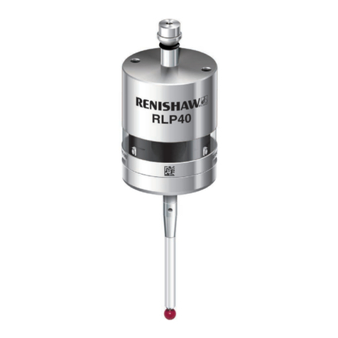
Renishaw RLP40 User manual

Renishaw

Renishaw RLP40 User manual

Renishaw OMP40 User manual

Renishaw

Renishaw OMP40 User manual

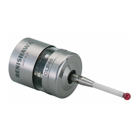
Renishaw OLP40 User manual

Renishaw

Renishaw OLP40 User manual

Renishaw RSP3 Series User manual

Renishaw

Renishaw RSP3 Series User manual

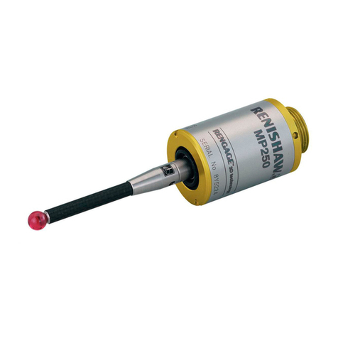
Renishaw MP250 User manual

Renishaw

Renishaw MP250 User manual

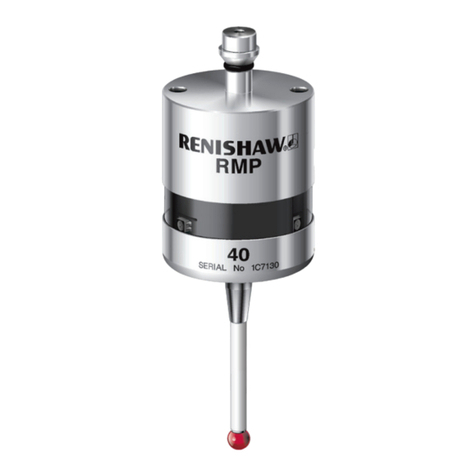
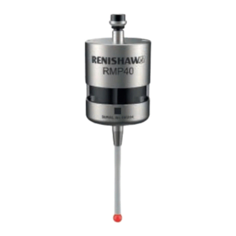
Renishaw RMP40 User manual

Renishaw

Renishaw RMP40 User manual

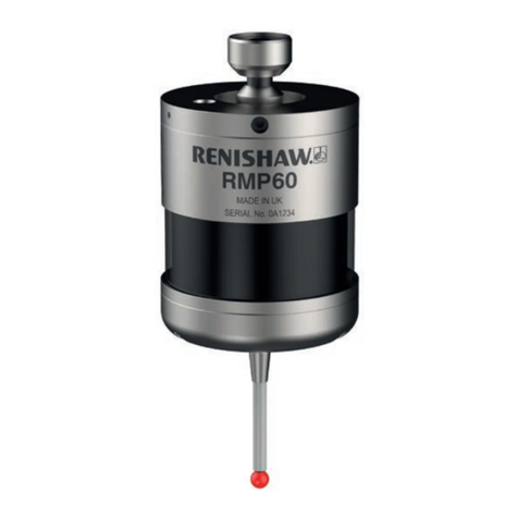
Renishaw RMP60 User manual

Renishaw

Renishaw RMP60 User manual

Renishaw MIH User manual

Renishaw

Renishaw MIH User manual

Renishaw RMP60QE User manual

Renishaw

Renishaw RMP60QE User manual

Renishaw RFP1 User manual

Renishaw

Renishaw RFP1 User manual

Renishaw OMP40-2 User manual

Renishaw

Renishaw OMP40-2 User manual

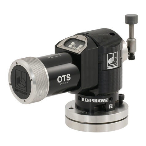
Renishaw OTS User manual

Renishaw

Renishaw OTS User manual

Renishaw RMP40QE User manual

Renishaw

Renishaw RMP40QE User manual

Renishaw MH8 User manual

Renishaw

Renishaw MH8 User manual

Renishaw RLP40 User manual

Renishaw

Renishaw RLP40 User manual

Renishaw RMP60 User manual

Renishaw

Renishaw RMP60 User manual

Renishaw RLP40 User manual

Renishaw

Renishaw RLP40 User manual

Renishaw OLP40 User manual

Renishaw

Renishaw OLP40 User manual

Renishaw TS34 User manual

Renishaw

Renishaw TS34 User manual

Renishaw RMP60 User manual

Renishaw

Renishaw RMP60 User manual

Renishaw RMP600 User manual

Renishaw

Renishaw RMP600 User manual

Renishaw OMP40-2 User manual

Renishaw

Renishaw OMP40-2 User manual

Renishaw RMP40 User manual

Renishaw

Renishaw RMP40 User manual

Renishaw RLP40 User manual

Renishaw

Renishaw RLP40 User manual

Popular Accessories manuals by other brands

ASTRO-PHYSICS 1100GTO manual

ASTRO-PHYSICS

ASTRO-PHYSICS 1100GTO manual

Mutsy IGO instruction manual

Mutsy

Mutsy IGO instruction manual

Belson UNIVERSAL DUAL DIFFUSER owner's manual

Belson

Belson UNIVERSAL DUAL DIFFUSER owner's manual

iso-9001 R-30 Installation and service manual

iso-9001

iso-9001 R-30 Installation and service manual

Ellia BLOSSOM quick start guide

Ellia

Ellia BLOSSOM quick start guide

IKEA tradfri manual

IKEA

IKEA tradfri manual

Siemens 3VT9200-4PA30 operating instructions

Siemens

Siemens 3VT9200-4PA30 operating instructions

Mimio Digital Ink Recording Setup guide

Mimio

Mimio Digital Ink Recording Setup guide

Sport-thieme 113 6526 Assembly instruction

Sport-thieme

Sport-thieme 113 6526 Assembly instruction

IFM Electronic efector 300 SU8001 operating instructions

IFM Electronic

IFM Electronic efector 300 SU8001 operating instructions

Philips DLA66067D brochure

Philips

Philips DLA66067D brochure

martens GTL720 operating manual

martens

martens GTL720 operating manual

Halma BEA MS09 Original instructions

Halma

Halma BEA MS09 Original instructions

Lightolier 1002P1 specification

Lightolier

Lightolier 1002P1 specification

Pranarom SOLEO user manual

Pranarom

Pranarom SOLEO user manual

SICK LMS1104C-111031S01 operating instructions

SICK

SICK LMS1104C-111031S01 operating instructions

Vehicle Weighing Solutions AIR WEIGHER M350S Quick setup guide

Vehicle Weighing Solutions

Vehicle Weighing Solutions AIR WEIGHER M350S Quick setup guide

Keli Sensing Technology D2008type user manual

Keli Sensing Technology

Keli Sensing Technology D2008type user manual

manuals.online logo
manuals.online logoBrands
  • About & Mission
  • Contact us
  • Privacy Policy
  • Terms and Conditions

Copyright 2025 Manuals.Online. All Rights Reserved.